Present address: ]Université de Lyon, ENS de Lyon, Université Claude Bernard, CNRS, Laboratoire de Physique, F-69342 Lyon, France Present address: ]Université Grenoble Alpes, CEA, INAC-Pheliqs, 38000 Grenoble, France Present address: ]Google, Santa Barbara CA 93117, USA.
Remote entanglement via adiabatic passage using a tunably-dissipative quantum communication system
Abstract
Effective quantum communication between remote quantum nodes requires high fidelity quantum state transfer and remote entanglement generation. Recent experiments have demonstrated that microwave photons, as well as phonons, can be used to couple superconducting qubits, with a fidelity limited primarily by loss in the communication channel Kurpiers et al. (2018); Axline et al. (2018); Campagne-Ibarcq et al. (2018); Leung et al. (2019); Zhong et al. (2019); Bienfait et al. (2019). Adiabatic protocols can overcome channel loss by transferring quantum states without populating the lossy communication channel. Here we present a unique superconducting quantum communication system, comprising two superconducting qubits connected by a 0.73 m-long communication channel. Significantly, we can introduce large tunable loss to the channel, allowing exploration of different entanglement protocols in the presence of dissipation. When set for minimum loss in the channel, we demonstrate an adiabatic quantum state transfer protocol that achieves 99% transfer efficiency as well as the deterministic generation of entangled Bell states with a fidelity of 96%, all without populating the intervening communication channel, and competitive with a qubit-resonant mode-qubit relay method. We also explore the performance of the adiabatic protocol in the presence of significant channel loss, and show that the adiabatic protocol protects against loss in the channel, achieving higher state transfer and entanglement fidelities than the relay method.
Remote entanglement of superconducting qubits has recently been demonstrated using both microwave photon- and phonon-mediated communication Kurpiers et al. (2018); Axline et al. (2018); Campagne-Ibarcq et al. (2018); Leung et al. (2019); Zhong et al. (2019); Bienfait et al. (2019). Many of these demonstrations are limited by loss in the communication channel, due to loss in the various microwave components or intrinsic to the channel itself Kurpiers et al. (2018); Leung et al. (2019); Bienfait et al. (2019); similar limitations apply to e.g. optically-based quantum communication systems. Adiabatic protocols analogous to stimulated Raman adiabatic passage (STIRAP) Vitanov et al. (2017); Bergmann et al. (2019) can mitigate such loss by adiabatically evolving an eigenstate of the system, using states that are “dark” with respect to the communication channel. These enable the high-fidelity coherent transfer of quantum states between sender and receiver nodes, even in the presence of large channel loss. Despite their use in a number of localized systems, such protocols have not been used for the generation of remote entangled states Vitanov et al. (2017); Bergmann et al. (2019).
In this Letter, we present a unique experimental system comprising a pair of superconducting transmon-style qubits linked by an on-chip, 0.73 m-long superconducting microwave transmission line. By changing the coupling of the transmission line to a resistive load, we can vary the transmission line’s energy lifetime over two orders of magnitude. We demonstrate an adiabatic protocol for quantum communication between the qubit nodes, compare its performance to a qubit-transmission mode-qubit relay method Sillanpaa et al. (2007); Ansmann et al. (2009); Zhong et al. (2019), and explore the performance of both protocols as a function of transmission loss.
We first describe the experimental device, then the two state transfer methods. We test the performance of each protocol in the low-loss limit, then as a function of transmission loss. The adiabatic process achieves significantly improved performance compared to the relay method, especially at intermediate levels of loss in the channel.
The two quantum state transfer methods, and the device we use to test them, are shown in Fig. 1. The device comprises two frequency-tunable superconducting xmon qubits Koch et al. (2007); Barends et al. (2013), and , each coupled to one end of the on-chip transmission line via an electrically-controlled tunable coupler Chen et al. (2014), and respectively (Fig. 1b). We use the qubit ground and excited states, whose transition frequency is tunable from 3 to 6 GHz. Qubit control is via low-frequency flux-tuning for control and quadrature-resolved microwave pulses for control. We read out the qubit states using standard dispersive measurements Schuster et al. (2005); Wallraff et al. (2005); Blais et al. (2004), via a capacitively-coupled readout resonator and a traveling-wave parametric amplifier. We projectively measure the excited state probability of each qubit with a fidelity of 88.80.8%.
The tunable couplers and allow us to externally control the coupling of each qubit to the individual resonant modes in the transmission line. A variable control consisting of two additional tunable couplers, and , is integrated into the transmission line, 1.6 mm from the coupler and its associated qubit . This circuit element provides electrically-controlled coupling between its input port and two output ports Chang et al. (2020). The coupler is placed inline with the transmission line and is always set to provide maximum coupling (and minimal reflection) to the remaining length of transmission line. The other coupler connects to port 1 on the sample mount, which is terminated by a lumped microwave load outside the sample box. Varying the coupling to this load allows us to set the loss in the transmission line, quantified by the energy lifetime of each resonant mode.
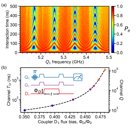
The transmission line of length m supports multiple resonant modes, separated in frequency by the free spectral range MHz, where ns is the photon one-way transit time in the channel. For sufficiently small qubit-resonator coupling, , each qubit can be selectively coupled to a single resonant mode in the transmission line. This is shown in Fig. 2a, where the transition frequency of qubit is tuned over 400 MHz, yielding four separate vacuum Rabi swap resonances spaced by the free spectral range . The loss coupler was set to minimum coupling, so the transmission line is limited only by its intrinsic loss. All experiments here were done with the mode at 5.351 GHz, just to the right of center in Fig. 2a.
In Fig. 2b, we demonstrate tunable control over the channel loss, using qubit to measure the lifetime of the resonant mode at 5.531 GHz as we vary the coupler and thus the transmission line loss. The pulse sequence for this measurement is shown inset in Fig. 2b. The mode energy decay time for each loss setting (controlled by the flux) is shown in Fig. 2b. With no coupling through , we measure the intrinsic resonant mode lifetime ns (orange), comparable to similar transmission lines without variable loss Zhong et al. (2019). With maximum coupling to the load, we measure a lifetime ns (blue), corresponding to a loaded quality factor , about 120 times smaller than the intrinsic quality factor of . We also measure the resonant mode’s Ramsey dephasing time at various flux bias points, and find , indicating the coupler introduces negligible additional phase decoherence. One non-ideality with this system is that qubit , due to its close proximity to the loss coupler , also has its lifetime reduced when the couplers and are both set to non-zero coupling, allowing energy loss from to the external load; this limits ’s performance, and is discussed further in the Supplementary Information Material . We note that this non-ideality can be avoided by placing the loss coupler in the middle of transmission line, as the transmission line would protect both qubits from the external load.
We used two different communication protocols, adiabatic transfer and a qubit-resonant mode-qubit relay method. Both methods were used for qubit state transfer via the transmission line as well as Bell state generation, both as a function of loss in the communication channel. The relay method uses a single extended mode in the transmission line, swapping an excitation from one qubit into that mode and subsequently swapping the excitation from that mode to the other qubit. This method is described in detail elsewhere Zhong et al. (2019); here it achieves an intrinsic loss-limited state transfer efficiency of and a Bell state fidelity of , where is the measured density matrix and is the reference Bell singlet state.
The adiabatic method uses the variable coupling of each qubit to the transmission line. When qubits and are set to the same frequency and couple to the same resonant mode in the channel with strengths and , the single-excitation Hamiltonian for the system can be written in the rotating frame as
| (1) |
where corresponds to () in () with photons in the resonant transmission line mode. This Hamiltonian supports a “dark” eigenstate that has no occupancy in the resonant mode,
| (2) |
where the mixing angle is given by . With set to zero and to its maximum, the dark state is , while exchanging the coupling values yields the dark state . By adiabatically varying the ratio in time from zero to its maximum, the system will swap the excitation from to , without populating the lossy intermediate channel Wang and Clerk (2012); Vitanov et al. (2017).
Here, we implement a simple adiabatic scheme Wang and Clerk (2012); Wang et al. (2017), where we vary the couplings in time according to and . We choose the parameters MHz and ns, minimizing the impact of finite qubit coherence while maintaining sufficient adiabaticity (see Material ). We note that the adiabatic protocol supports better than transfer efficiency even when ; see Material .
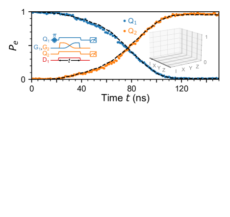
In Fig. 3a, we demonstrate deterministic adiabatic state transfer from to . With in and and set on-resonance with a single mode in the channel, we adjust the couplers and adiabatically to complete the state transfer. We show the excited state population of each qubit as a function of time , measured with the resonant mode loss at its intrinsic minimum. We observe the expected gradual population transfer from to , with ’s population reaching its maximum at , with a transfer efficiency . We further characterize the state transfer by carrying out quantum process tomography Neeley et al. (2008), yielding the process matrix shown inset in Fig. 3a, with a process fidelity , limited by qubit decoherence. The process matrix calculated from a master equation simulation displays a small trace distance to the measured matrix of , indicating excellent agreement with experiment.
The adiabatic protocol can also be used to generate remote entanglement between and . With prepared in , we share half its excitation with using the adiabatic protocol, by stopping the transfer at its midpoint . This generates a Bell singlet state . The qubit excited state population is shown as function of time in Fig. 3b. We further characterize the Bell state by quantum state tomography Steffen et al. (2006); Neeley et al. (2010), and the reconstructed density matrix is shown inset in Fig. 3b. We find a Bell state fidelity , referenced to the ideal Bell singlet state , and a concurrence (see Material ). The density matrix calculated from a master equation simulation shows a small trace distance to the measured , , indicating excellent agreement with experiment.
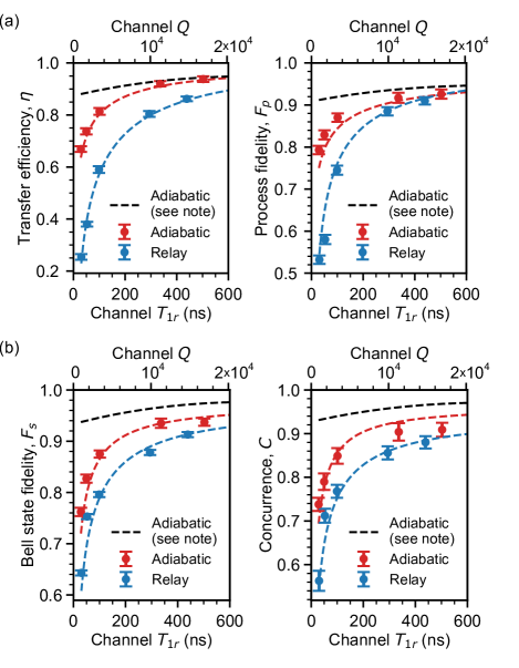
We explore the impact of loss on both the relay method and the adiabatic protocol, with results shown as a function of the resonant channel mode energy lifetime in Fig 4. For the highest level of dissipation, with ns, we measure an adiabatic transfer efficiency , even though the transfer time is four times the resonant mode lifetime. The efficiency is primarily limited by loss in qubit due to its spurious coupling loss through to the load (see Material ), in good agreement with master equation simulations. Results from a simulation without the spurious coupling are plotted as black dashed lines in Fig 4a, limited by a small channel occupation due to the finite adiabaticity of the sequence. We compare these results to the relay method, where we use a weak coupling MHz to ensure the qubits only couple to a single transmission line mode; this results in a total transfer time ns. We find the adiabatic protocol consistently performs better than the relay method, with a higher transfer efficiency ( reduction in transfer loss) and higher process fidelity ( reduction in process infidelity) compared to the relay method in the most dissipative case; the adiabatic protocol is primarily limited by spurious coupling loss in , while the relay method is limited by loss in the channel (see Material ).
In Fig. 4b, we display the entanglement fidelity using the adiabatic protocol with different levels of channel loss, and compare to the relay method. The adiabatic protocol outperforms the relay method in all levels of dissipation. At the highest loss level, where ns, the adiabatic protocol achieves higher Bell state fidelity ( reduction in Bell state infidelity) and higher concurrence ( reduction in concurrence infidelity) compared to the relay method; the spurious-coupling-free simulation result for the adiabatic protocol is shown by the black dashed lines, limited by a small channel occupation due to the finite adiabaticity of the sequence.
In conclusion, we describe a unique experimental system in which we can explore the performance of quantum communication protocols in the presence of controllable communication loss. We demonstrate an adiabatic protocol that realizes high-fidelity transfer of quantum states and entangled Bell states, limited mostly by spurious coupling of one qubit to the controlled transmission line loss. The platform we have developed is well-suited to explore the impact of channel loss on other error-protecting quantum communication protocols, such as heralding Mosley et al. (2008); Azuma et al. (2015); Kurpiers et al. (2019) and entanglement distillationKwiat et al. (2001); Dong et al. (2008); Takahashi et al. (2010). The ability to introduce controlled loss dynamically into the system opens the door to study dissipative dynamics in non-equilibrium systems, enabling approaches such as reservoir engineering Poyatos et al. (1996); Plenio and Huelga (2002). The adiabatic protocol demonstrated here is applicable to other quantum communication systems, for example phonon-based systems where the communication channel is significantly more lossy Hermelin et al. (2011); McNeil et al. (2011); Bienfait et al. (2019). Future demonstrations could employ more advanced adiabatic protocols such as shortcuts to adiabaticity Baksic et al. (2016); Zhou et al. (2017) and composite adiabatic passage Torosov et al. (2011); Bruns et al. (2018) to further improve fidelity.

Acknowledgements.
The authors thank A. A. Clerk, P. J. Duda, and B. B. Zhou for helpful discussions. We thank W. D. Oliver and G. Calusine at MIT Lincoln Lab for providing the traveling-wave parametric amplifier (TWPA) used in this work. Devices and experiments were supported by the Air Force Office of Scientific Research and the Army Research Laboratory. K.J.S. was supported by NSF GRFP (NSF DGE-1144085), É.D. was supported by LDRD funds from Argonne National Laboratory; A.N.C. was supported in part by the DOE, Office of Basic Energy Sciences. This work was partially supported by the UChicago MRSEC (NSF DMR-1420709) and made use of the Pritzker Nanofabrication Facility, which receives support from SHyNE, a node of the National Science Foundation’s National Nanotechnology Coordinated Infrastructure (NSF NNCI-1542205). The authors declare no competing financial interests. Correspondence and requests for materials should be addressed to A. N. Cleland (anc@uchicago.edu).References
- Kurpiers et al. (2018) P. Kurpiers, P. Magnard, T. Walter, B. Royer, M. Pechal, J. Heinsoo, Y. Salathe, A. Akin, S. Storz, J.-C. Besse, S. Gasparinetti, A. Blais, and A. Wallraff, Nature 558, 264 (2018).
- Axline et al. (2018) C. J. Axline, L. D. Burkhart, W. Pfaff, M. Zhang, K. Chou, P. Campagne-Ibarcq, P. Reinhold, L. Frunzio, S. M. Girvin, L. Jiang, M. H. Devoret, and R. J. Schoelkopf, Nature Physics 14, 705 (2018).
- Campagne-Ibarcq et al. (2018) P. Campagne-Ibarcq, E. Zalys-Geller, A. Narla, S. Shankar, P. Reinhold, L. Burkhart, C. Axline, W. Pfaff, L. Frunzio, R. J. Schoelkopf, and M. H. Devoret, Physical Review Letters 120, 200501 (2018).
- Leung et al. (2019) N. Leung, Y. Lu, S. Chakram, R. K. Naik, N. Earnest, R. Ma, K. Jacobs, A. N. Cleland, and D. I. Schuster, npj Quantum Information 5, 18 (2019).
- Zhong et al. (2019) Y. P. Zhong, H.-S. Chang, K. J. Satzinger, M.-H. Chou, A. Bienfait, C. R. Conner, É. Dumur, J. Grebel, G. A. Peairs, R. G. Povey, D. I. Schuster, and A. N. Cleland, Nature Physics 15, 741 (2019).
- Bienfait et al. (2019) A. Bienfait, K. J. Satzinger, Y. P. Zhong, H.-S. Chang, M.-H. Chou, C. R. Conner, É. Dumur, J. Grebel, G. A. Peairs, R. G. Povey, and A. N. Cleland, Science 364, 368 (2019).
- Vitanov et al. (2017) N. V. Vitanov, A. A. Rangelov, B. W. Shore, and K. Bergmann, Reviews of Modern Physics 89, 015006 (2017).
- Bergmann et al. (2019) K. Bergmann, H.-C. Nagerl, C. Panda, G. Gabrielse, E. Miloglyadov, M. Quack, G. Seyfang, G. Wichmann, S. Ospelkaus, A. Kuhn, S. Longhi, A. Szameit, P. Pirro, B. Hillebrands, X.-F. Zhu, J. Zhu, M. Drewsen, W. K. Hensinger, S. Weidt, T. Halfmann, H.-L. Wang, G. S. Paraoanu, N. V. Vitanov, J. Mompart, T. Busch, T. J. Barnum, D. D. Grimes, R. W. Field, M. G. Raizen, E. Narevicius, M. Auzinsh, D. Budker, A. Pálffy, and C. H. Keitel, Journal of Physics B: Atomic, Molecular and Optical Physics 52, 202001 (2019).
- Sillanpaa et al. (2007) M. A. Sillanpaa, J. I. Park, and R. W. Simmonds, Nature 449, 438 (2007).
- Ansmann et al. (2009) M. Ansmann, H. Wang, R. C. Bialczak, M. Hofheinz, E. Lucero, M. Neeley, A. D. O’Connell, D. Sank, M. Weides, J. Wenner, A. N. Cleland, and J. M. Martinis, Nature 461, 504 (2009).
- Koch et al. (2007) J. Koch, T. M. Yu, J. Gambetta, A. A. Houck, D. I. Schuster, J. Majer, A. Blais, M. H. Devoret, S. M. Girvin, and R. J. Schoelkopf, Physical Review A 76, 042319 (2007).
- Barends et al. (2013) R. Barends, J. Kelly, A. Megrant, D. Sank, E. Jeffrey, Y. Chen, Y. Yin, B. Chiaro, J. Mutus, C. Neill, P. O’Malley, P. Roushan, J. Wenner, T. C. White, A. N. Cleland, and J. M. Martinis, Physical Review Letters 111, 080502 (2013).
- Chen et al. (2014) Y. Chen, C. Neill, P. Roushan, N. Leung, M. Fang, R. Barends, J. Kelly, B. Campbell, Z. Chen, B. Chiaro, A. Dunsworth, E. Jeffrey, A. Megrant, J. Y. Mutus, P. J. J. O’Malley, C. M. Quintana, D. Sank, A. Vainsencher, J. Wenner, T. C. White, M. R. Geller, A. N. Cleland, and J. M. Martinis, Physical Review Letters 113, 220502 (2014).
- Schuster et al. (2005) D. I. Schuster, A. Wallraff, A. Blais, L. Frunzio, R.-S. Huang, J. Majer, S. M. Girvin, and R. J. Schoelkopf, Physical Review Letters 94, 123602 (2005).
- Wallraff et al. (2005) A. Wallraff, D. I. Schuster, A. Blais, L. Frunzio, J. Majer, M. H. Devoret, S. M. Girvin, and R. J. Schoelkopf, Physical Review Letters 95, 060501 (2005).
- Blais et al. (2004) A. Blais, R.-S. Huang, A. Wallraff, S. M. Girvin, and R. J. Schoelkopf, Physical Review A 69, 062320 (2004).
- Chang et al. (2020) H.-S. Chang, Y. P. Zhong, K. J. Satzinger, M.-H. Chou, A. Bienfait, C. R. Conner, É. Dumur, J. Grebel, G. A. Peairs, R. G. Povey, and A. N. Cleland, In preparation (2020).
- (18) S. Material, .
- Wang and Clerk (2012) Y.-D. Wang and A. A. Clerk, New Journal of Physics 14, 105010 (2012).
- Wang et al. (2017) Y.-D. Wang, R. Zhang, X.-B. Yan, and S. Chesi, New Journal of Physics 19, 093016 (2017).
- Neeley et al. (2008) M. Neeley, M. Ansmann, R. C. Bialczak, M. Hofheinz, N. Katz, E. Lucero, A. O’Connell, H. Wang, A. N. Cleland, and J. M. Martinis, Nature Physics 4, 523 (2008).
- Steffen et al. (2006) M. Steffen, M. Ansmann, R. C. Bialczak, N. Katz, E. Lucero, R. McDermott, M. Neeley, E. M. Weig, A. N. Cleland, and J. M. Martinis, Science 313, 1423 (2006).
- Neeley et al. (2010) M. Neeley, R. C. Bialczak, M. Lenander, E. Lucero, M. Mariantoni, A. D. O’Connell, D. Sank, H. Wang, M. Weides, J. Wenner, Y. Yin, T. Yamamoto, A. N. Cleland, and J. M. Martinis, Nature 467, 570 (2010).
- Mosley et al. (2008) P. J. Mosley, J. S. Lundeen, B. J. Smith, P. Wasylczyk, A. B. U’Ren, C. Silberhorn, and I. A. Walmsley, Physical Review Letters 100, 133601 (2008).
- Azuma et al. (2015) K. Azuma, K. Tamaki, and H.-K. Lo, Nature Communications 6, 6787 (2015).
- Kurpiers et al. (2019) P. Kurpiers, M. Pechal, B. Royer, P. Magnard, T. Walter, J. Heinsoo, Y. Salathe, A. Akin, S. Storz, J.-C. Besse, S. Gasparinetti, A. Blais, and A. Wallraff, Physical Review Applied 12, 044067 (2019).
- Kwiat et al. (2001) P. G. Kwiat, S. Barraza-Lopez, A. Stefanov, and N. Gisin, Nature 409, 1014 (2001).
- Dong et al. (2008) R. Dong, M. Lassen, J. Heersink, C. Marquardt, R. Filip, G. Leuchs, and U. L. Andersen, Nature Physics 4, 919 (2008).
- Takahashi et al. (2010) H. Takahashi, J. S. Neergaard-Nielsen, M. Takeuchi, M. Takeoka, K. Hayasaka, A. Furusawa, and M. Sasaki, Nature Photonics 4, 178 (2010).
- Poyatos et al. (1996) J. F. Poyatos, J. I. Cirac, and P. Zoller, Physical Review Letters 77, 4728 (1996).
- Plenio and Huelga (2002) M. B. Plenio and S. F. Huelga, Physical Review Letters 88, 197901 (2002).
- Hermelin et al. (2011) S. Hermelin, S. Takada, M. Yamamoto, S. Tarucha, A. D. Wieck, L. Saminadayar, C. Bauerle, and T. Meunier, Nature 477, 435 (2011).
- McNeil et al. (2011) R. P. G. McNeil, M. Kataoka, C. J. B. Ford, C. H. W. Barnes, D. Anderson, G. A. C. Jones, I. Farrer, and D. A. Ritchie, Nature 477, 439 (2011).
- Baksic et al. (2016) A. Baksic, H. Ribeiro, and A. A. Clerk, Physical Review Letters 116, 230503 (2016).
- Zhou et al. (2017) B. B. Zhou, A. Baksic, H. Ribeiro, C. G. Yale, F. J. Heremans, P. C. Jerger, A. Auer, G. Burkard, A. A. Clerk, and D. D. Awschalom, Nature Physics 13, 330 (2017).
- Torosov et al. (2011) B. T. Torosov, S. Guerin, and N. V. Vitanov, Physical Review Letters 106, 233001 (2011).
- Bruns et al. (2018) A. Bruns, G. T. Genov, M. Hain, N. V. Vitanov, and T. Halfmann, Physical Review A 98, 053413 (2018).