- MR
- Magnetic Resonance
- CT
- Computed Tomography
- CT
- Computed micro-Tomography
- UGCT
- Ghent University Centre for X-Ray Tomography
- RP
- Radiation Physics
- GPU
- Graphics Processing Unit
- SART
- Simultaneous Algebraic Reconstruction Technique
- DART
- Discrete Algebraic Reconstruction Technique
- FBP
- Filtered Back-Projection
- NN-hFBP
- Neural Network Hilbert transform based Filtered Back-Projection (FBP)
- pixel
- picture element
- voxel
- volume element
- SOD
- Source Object Distance
- SDD
- Source Detector Distance
- ROI
- Region Of Interest
- number of projections
- number of azimuthal voxels
- number of radial voxels
- MTF
- Modulation Transfer Function
- radial MTF
- azimuthal MTF
- NDT
- Non-Destructive Testing
- RHT
- Randomized Hough Transform
22email: wannes.goethals@ugent.be 33institutetext: M. Heyndrickx 44institutetext: 44email: marjolein.heyndrickx@ugent.be 55institutetext: M. Boone 66institutetext: 66email: matthieu.boone@ugent.be
Fast tomographic inspection of cylindrical objects
Abstract
This paper presents a method for improved analysis of objects with an axial symmetry using X-ray Computed Tomography (CT).
Cylindrical coordinates about an axis fixed to the object form the most natural base to check certain characteristics of objects that contain such symmetry, as often occurs with industrial parts.
The sampling grid corresponds with the object, allowing for down-sampling hence reducing the reconstruction time. This is necessary for in-line applications and fast quality inspection.
With algebraic reconstruction it permits the use of a pre-computed initial volume perfectly suited to fit a series of scans where same-type objects can have different positions and orientations, as often encountered in an industrial setting.
Weighted back-projection can also be included when some regions are more likely subject to change, to improve stability.
Building on a Cartesian grid reconstruction code, the feasibility of reusing the existing ray-tracers is checked against other researches in the same field.
Keywords:
X-rays, tomography, 3D inspection, in-line1 Introduction
Non-destructive evaluation, either in-line or on random test samples, is paramount in a modern production environment to detect internal faults at an early stage. For assembled products, a common fault case is the situation where a component is missing in the final product. These components are often concealed in the assembly, hindering visual inspection. X-ray based imaging may offer better insight on manufacturing quality.
For in-line inspection, X-ray transmission scanning is usually applied to make 2D projection images. Common examples can be found in defect detection haff2008x ; zou2015automatic ; xu2010automatic or material identification duvillier2018inline . On the other hand, the more intensive 3D imaging by X-ray CT is mainly used off-line.
The first industrial applications of CT can be found since the 1980s in the field of material analysis, e.g. observing inner structure and processes or locating internal defects.
More recently, CT scanners are being used dedicated to metrology for dimensional quality control. High importance is given in this case to accuracy, traceability to the unit of length and measurement uncertainty kruth2011computed ; ametova2018computationally ; jones2018limited .
New developments in CT technology, driven by research at synchrotron facilities and medical imaging, allow the technology to be applied in an automated production environment too shefer2013state ; Thomas2016line .
As the industry is gradually becoming aware of the options that X-ray CT offers as a non-destructive 3D inspection tool, this leads to the demand for systems specifically designed for scanning sequences of same-type objects in a high throughput environment.
The challenges lie in the fact that a variety of factors restrict the number of projections to as low as technically feasible.
The solutions can be found in more advanced reconstruction techniques like discrete reconstruction batenburg2011dart or neural-network based solutions janssens2018neural .
Even though iterative reconstructions can’t compete with the analytic counterparts in terms of reconstruction time for standard cone-beam geometry, they allow making fewer projections with still reasonable results by incorporating prior knowledge. This reduces the scan time and the absorbed radiation dose per object.
Previous studies have shown that iterative reconstruction schemes using cylindrical coordinates can alleviate memory requirements and be less subject to noise than FBP algorithms Thibaudeau . As a negative point of attention, Jian et al. Jian reported a loss in resolution due to non-uniform sampling.
In these studies, the cylindrical coordinate axis is positioned along the vertical axis of the rotation stage.
In this work the specific choice is made not to fix the reconstruction axis to the vertical rotation axis, but to attach the coordinate system to the detected symmetry axis of the scanned object.
In an industrial environment, misalignment of this axis w.r.t. the measurement system happens most of the cases, so it can’t be ignored.
This tracking reconstruction is computationally more intensive, as it excludes the reported acceleration of the algorithms mentioned before. It will however be highly beneficial in both the reconstruction and analysis phase. A point-tracking technique, presented in part 2.1, has been developed to automatically derive the 3D pose of the scanned object from the projection images. Given the simple symmetry no extension to more demanding deep learning techniques bui2017x should be made, however interesting they may be. It is important to note that this technique is not limited to standard circular trajectories. For a high continuous throughput that’s aimed at in industrial applications, a conveyor belt trajectory Thomas2016line could be used.
With this prior knowledge the algebraic reconstruction can be improved by including an initial solution that automatically has a correct orientation. Regions can be marked to have a high or low probability of change to improve reconstruction stability Marjolein . These previous developments are not affected by the coordinate base change of the reconstruction described in part 2.2. The effect of aimed resampling is demonstrated on simulated data in section 2.3 and improved reconstruction algorithms in cylindrical coordinates are applied on a large series of scans in 2.4.
2 Methods and materials
Two techniques are used to offer a better framework in the CT reconstruction of misaligned cylindrical objects.
-
1.
To detect the cylinder orientation from the projection data, a point tracking algorithm is made for general trajectories.
-
2.
The cylindrical reconstruction is built as an extension of a regular Cartesian Simultaneous Algebraic Reconstruction Technique (SART).
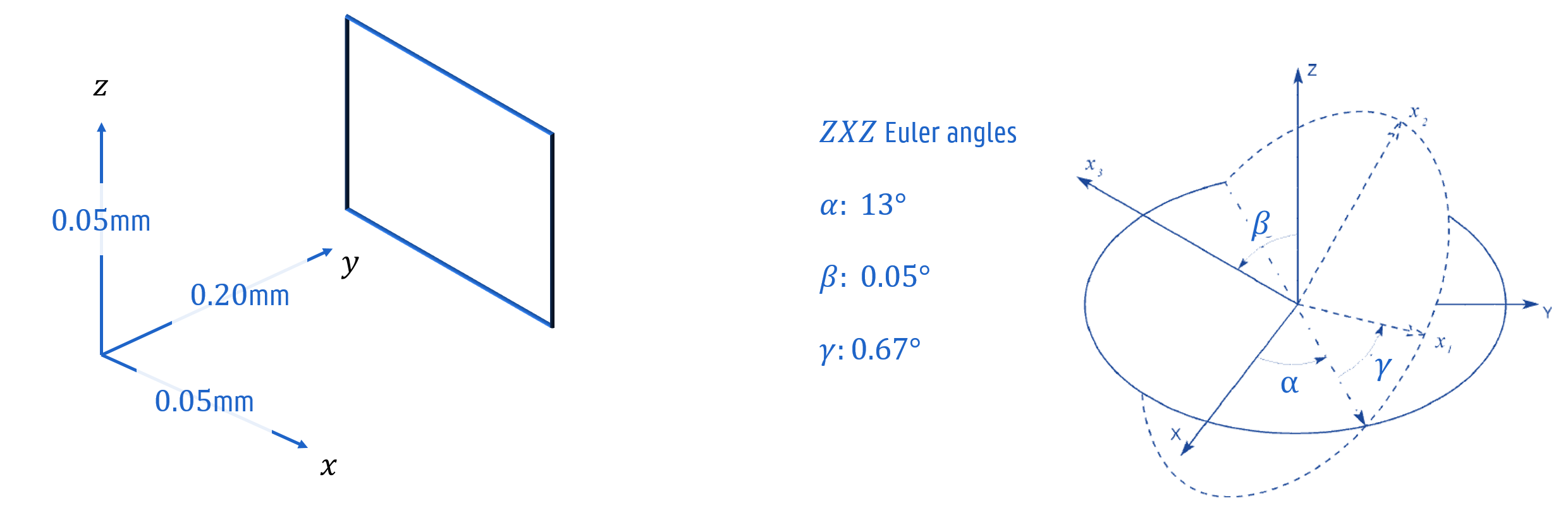
The object’s pose, illustrated in figure 1, can be captured in six degrees of freedom. Three intrinsic Euler angles are captured in the rotation matrix , while translates the object along the three spatial coordinates:
| (1) |
After the alignment from to in equation (1), a transformation to cylindrical coordinates around the z’-axis is performed on this oriented set of coordinates:
| (2) |
2.1 Projection based pose estimation
Point tracking
Given a single point in the 3D volume space , the horizontal and vertical projected coordinate of the corresponding volume element or voxel can be uniquely determined given the view transformations of the source-volume-detector system. The inverse problem of projection-based point tracking is ill-posed as any point lying on the straight line coming from the source point can cast a shadow on the given detector pixel. Combining projections from different directions will overcome this problem and leave you with an overdetermined set of non-linear equations due to the conical shape of the beam.
| (3) |
The Levenberg-Marquardt algorithm marquardt1963 yields a solution that minimizes the sum of squared projection distances. Derivatives of can be calculated analytically.
| (4) |
Axis tracking
To track the cylinder axis, two 3D points along the axis are sufficient to fix five degrees of freedom, leaving the internal rotation as a last free parameter. In practice these points can be seen by finding the symmetry axis of the cylindrical object on the projections. Due to the symmetric nature of the objects, this algorithm can be executed very fast using tailor-made Graphics Processing Unit (GPU) techniques. This technique of projection-based pose estimation may be impossible for objects of lower symmetry.
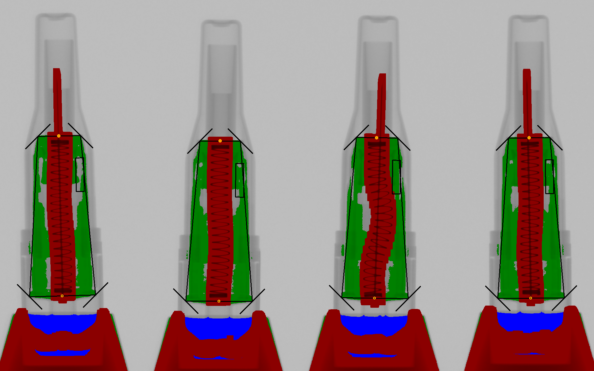
A practical implementation is illustrated in figure 2. First the most stable symmetric feature is segmented by threshold and dilation techniques. Then the pairwise centres of the four corner pixels are assumed to be on the symmetry axis. These two centres are tracked on each projection and in this way the 3D position of the object can be calculated using equation (4). Two other techniques have been looked into, but although they were not successful in this particular case, they can be of use in other applications. The first one, using the mean and the covariance matrix of the segmented piece, is affected too much by internal variations of the object. The position and angle of the segmented object can also be achieved using the minAreaRect function of OpenCV itseez2015opencv . This works by finding the bounding rotated rectangle with minimal area around the segment. Here internal intensity fluctuations at the outer edges affect the outcome as well.
Azimuthal phase
In some cases it may be necessary to know the azimuthal phase of the object before reconstructing. When a detailed initial solution or weighted volume is used, any internal rotation of the object will produce false features in the reconstruction. This last Euler angle can be derived by monitoring the grey value fluctuations in a region parallel to the projected axis. This will give similar results in function of the projection angle, only phase shifted due to the object’s internal rotation and the geometrical angle w.r.t. the optical axis of the scanner.
This perceived phase shift can be translated back to the last Euler angle when a correction for the first Euler angles and is also taken into account. After all, the phase was calculated w.r.t. the original -axis, not the -axis.
| (5) |
2.2 SART reconstruction in cylindrical coordinate system
CT reconstruction seeks to calculate the distribution of attenuation coefficients of an object given the projected X-ray intensities on the detector for a number of projection angles. The basic operation in these methods is back-projection, which tries to invert the set of monochromatic Lambert-Beer equations for all pixel values to a grid of attenuation coefficients :
| (6) |
The weights represent the intersection length of the ray passing through the voxel , where runs over all pixels of all projection images. In the SART approach, the solution is found by updating each voxel with a correction factor that’s found by comparing the actual projection with a simulation on the current state of the volume Thomas . This update step is performed for each projection in SART. The correction factor is accompanied by the relaxation which dampens the contribution to each update.
| (7) |
The projection step is calculated in a pixel driven sampling approach, by tracing the rays between source and detector pixel with an equidistant sampling scheme in Cartesian space. The ray-voxel intersection weights are calculated intrinsically as the number of samplings in each voxel. The current attenuation coefficients are interpolated on the cylindrical grid. This method is also easily extendible to other division schemes.
The same strategy can be used for the back-projection step, which is executed in a voxel driven approach. Only the simple coordinate transform (2) is applied before the corresponding correction term is accessed. The total overhead translates in this case to one cylindrical transformation each time a volume access is performed. Only the alignment matrix needs to be precomputed for equation (1). Weighted back-projection, as implemented by Heyndrickx et al. Marjolein2016prior , is adapted similarly by performing the right coordinate transforms. A weight map is prepared in cylindrical coordinates to indicate how severely regions can be subject to change.
2.3 MTF measurements on phantom data
Due to the way that the reconstruction grid is divided, the number of azimuthal divisions can be changed effortlessly. Depending on the application, reducing the number of voxels in a direction that contains broad, smooth structures can be tolerated or may even be necessary to reduce aliasing effects.
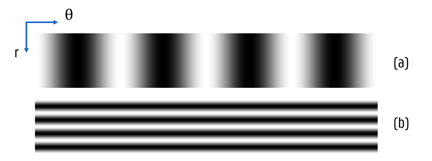
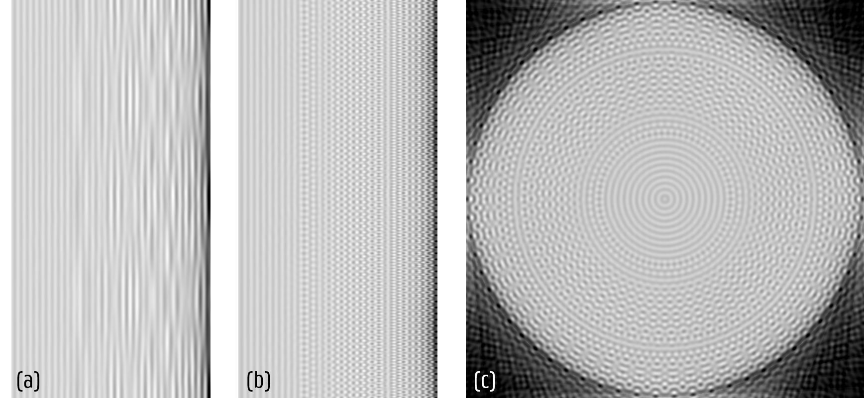
To get a sense of the resolution dependence on the number of azimuthal voxels () and number of radial voxels (), we perform a high detail simulation on samples consisting of radial or azimuthal lines as shown in figure 3. Then the directional Modulation Transfer Function (MTF) boreman2001modulation (radial or azimuthal MTF) of the reconstruction is determined by measuring the modulation (resp. and ) for varying frequency factor, i.e. the number of lines in the phantom of constant size. The modulation for a given frequency is determined by measuring the minimum and maximum reconstructed attenuation coefficients and in the central slice (to eliminate the effect of cone beam artefacts).
| (8) |
This value varies between and , given the positive values of . A value of is expected to be the result of a good response of the reconstruction algorithm to the used phantom frequency. However, one downside to this measure is that it does not punish aliasing effects that alter the line frequency but maintain the modulation depth. A visual inspection is also required to investigate these faulty cases.
In all reconstructions, also the radial dependency of the MTF is measured. For the azimuthal MTF () this is simply the MTF at each . The radial dependency of the radial MTF () is calculated with a short-range sliding window over the line period. The window width is equal to one period of the phantom. The slide step is equal to the width instead of voxel, for ease of implementation.
The lines are modelled by a cosine function on the respective direction. For the , each slice of the phantom looks like a Siemens star pattern gonzalez2015mtf . The is measured in a phantom of concentric circles.
Highly detailed projections are simulated on these samples of shape .
The frequencies are doubled until a factor of is reached.
The image is projected on 4096 images of dimensions to reduce the influence of sampling artefacts in the simulation step.
2.4 Application in batch CT scan inspection
To illustrate how the developed strategy can be applied in a real production environment, a scan was performed on a series of medical devices with high safety demands. 50 objects have been scanned, reconstructed and analysed for artificially induced internal defects. To measure the axis detection precision and to assess the influence of the scanner geometry, the same samples have been scanned repeatedly with different centres of rotation. The pose w.r.t. the rotation stage is constant. The projected horizontal coordinates of the rotation stage are , , , and pixels. For the geometry displayed in table 1, the precision is measured as the standard deviation of the pose estimation for the five consecutive scans. This measurement is done over for 50 samples.
| Geometry | Circular cone beam | ||||
| Source Detector Distance | SDD | 791 | mm | ||
| Source Object Distance | SOD | 679 | mm | ||
| Number of projections | 21 | ||||
| Last scan angle | 200 | ||||
| Detector | Varex 1512 | ||||
| Detector size | (H,W) | (1536,1944) | |||
| Detector pixel size | 0.748 | mm | |||
| Sample | KN-S | ||||
| Height | 64 | mm | |||
| Radius | 8 | mm |
3 Results
3.1 Characterization on simulated data
The and at reconstruction shape are shown in figure 4. As expected, the MTF becomes worse at high frequent lines. The azimuthal MTF shows worse behaviour at small radii. Even though the voxel size is virtually decreased at lower , the actual resolution doesn’t automatically follow this trend. For the radial MTF, only a minor effect of the centre distance can be observed in figure 4(b).
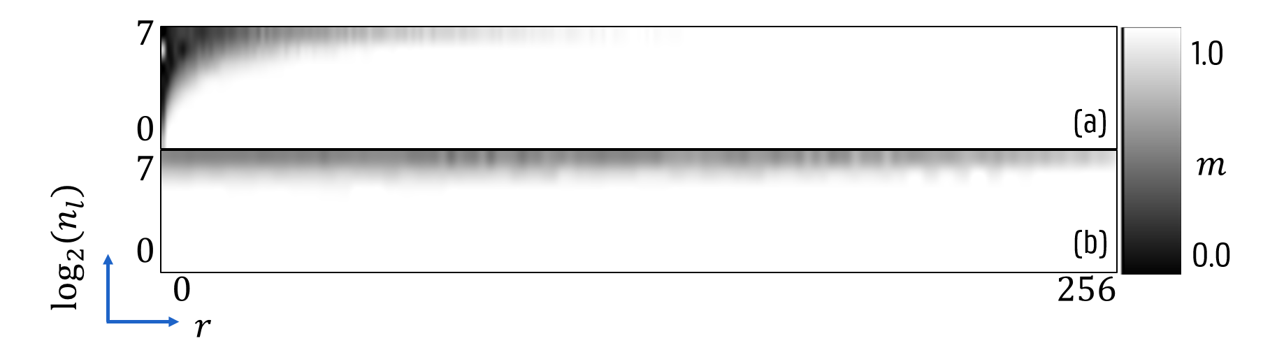
No variation of the was noted for any between 1 and 512. Do note that this is a very extreme phantom and the results will probably be a mixed term in real objects.
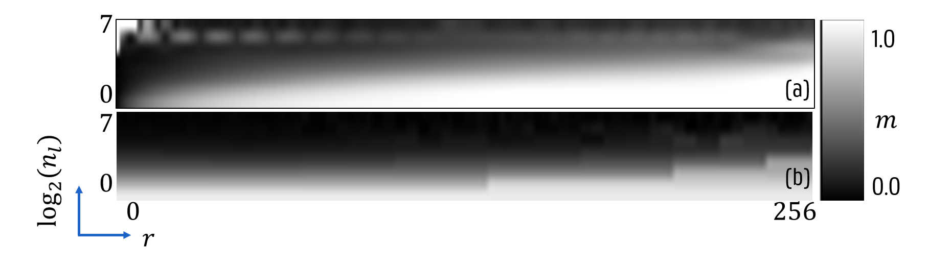
The same exercise has been done over for a lower number of projections (). Now instead of projections were simulated and the same reconstruction shape was used. Similar results have been noted for projections, the odd number of was chosen to avoid any numerical bias. These results are shown in figure 5 and the modulation factor is lower than the previous outcome as expected. More variation can be observed for the phantom in the radial direction. When we look at the reconstructed slices in figure 6, the origin of the seemingly good at high is revealed. Due to the insufficient amount of projections, aliasing effects appear in the reconstruction. Actually, the quality is better at low where no azimuthal aliasing shows up at lower frequencies. Decreasing the number of azimuthal divisions to the order of the projections number gives more truthful results, though the aliasing is still visible. When the same radial resolution is required at a greater distance from the central axis, a higher is required. This requirement remains true for hollow cylinders. Understanding these aliasing effects can help in the development of more advanced sampling strategies.
3.2 Precision of pose estimation
A scan has been performed in a geometry that resembles an in-line CT inspection set-up. As can be seen in table 1, the objects are placed rather close to the wide detector in order to scan more samples at the same time. For these scans, the axis detection using the extremal corner pixels took only s.
The minAreaRect technique took s on average, so this alternative was not used.
The precision of the pose estimation, derived as explained in paragraph 2.4, is shown in figure 7. The translational precision is better in the transversal directions. Due to the small angle, seems to suffer bad precision, though this is only a mathematical issue due to the used Euler angle convention. The difference in and might be attributed to the limited angle of in which projections were taken. The overall good precision is necessary to assure a qualitative reconstruction.
The practical difficulties of this method are present in the segmentation phase, as demonstrated in figure 2. The projected intensity won’t be constant for a given cylindrical object. The total attenuation will be less at the cylinder edges, where a smaller amount of material was traversed. A simple threshold technique may be affected by disturbing features in the object. In this case the sample holder at the image bottom and the metal components reduce the projected intensity. To remove this degeneracy in grey values, the other features are separately thresholded and dilated before removing them from the collection of foreground pixels. The sample holders assure already a rough estimate of the positions so some regions can already be excluded.
3.3 Use of initial volume and back-projection weights in cylindrical reconstruction algorithms
The added value of the initial solution and the weighted back-projection are investigated for the batch scan with settings listed in table 1. The number of voxels in the cylindrical reconstruction is for a virtual voxel size of mm. Reconstruction times changed from s for a normal one, to s for a weighted back-projection reconstruction. In figure 8, the results are illustrated for each distinct reconstruction strategy:
-
(a)
The object is reconstructed without aid of initial volume or weighted back-projection.
-
(b)
Include an initial solution, which is considered to be the dangerous approach in the case of missing components. The iterative algorithm might not remove these sufficiently.
-
(c)
Initial solution combined with weighted back-projection. Some predefined regions are given higher weights to change their attenuation value.
-
(d)
Only weighted back-projection: the algorithm starts from a completely empty volume.


From figure 8, one can derive a number of preliminary conclusions. When no prior info is included, the slices have low contrast and sharpness. This will negatively affect the later analysis phase where image characteristics are converted to binary results (present / missing). In sub-figure 8 a higher sharpness is perceived compared to 8, but this also illustrates an important aspect of the algorithm: when the volume is badly aligned with the initial solution, some ghost effects may appear (particularly in the azimuthal direction). The weighted approaches in figures 8 and 8 improve the contrast, while the latter doesn’t include an initial solution.
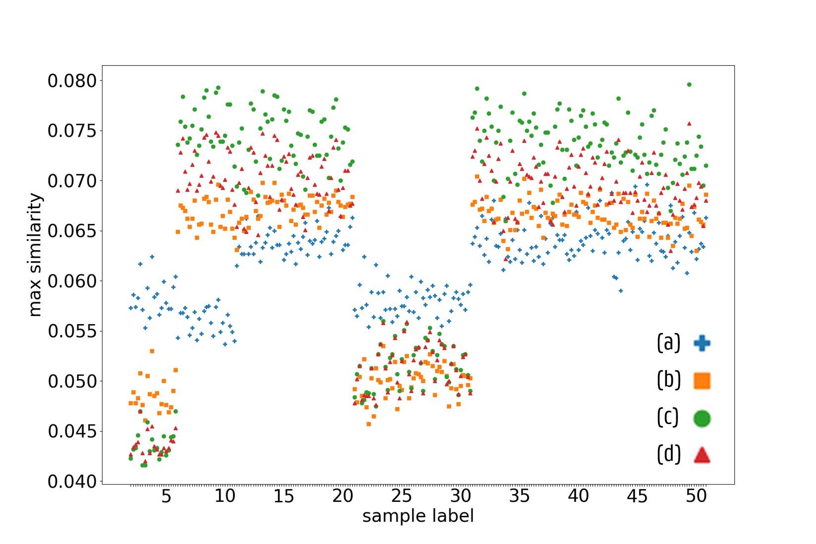
The results can also be observed in the test measuring the piece presence, described earlier. Figure 9 shows the distribution of this measure for the different methods. It is clear that the difference between the groups has increased most when an initial volume and weights are included. This clear distinction is necessary to increase the detection rate of the internal defects without discarding safe devices.
4 Conclusion
In this work two techniques have been developed in the scope of high-throughput CT inspection of cylindrical objects. These are necessary to reduce scan time while maintaining reasonable image quality. A pose estimation technique for cylindrical objects has been implemented that uses only basic segmentation algorithms on the projected images. The axis extraction using the corner information was found to be both fast and precise. Reconstruction was performed directly in the aligned cylindrical coordinate system.
The MTF characterization shows how reliably the scanner can reconstruct different frequencies of the (phantom) object. The artificially high number of azimuthal divisions at low radius should only be interpreted as a mathematical construct. The actual resolution corresponds more to the Cartesian voxel size. The number of divisions could be matched better with the actual content of the object. When the components only have a low frequency in the azimuthal direction, the user may choose to drop the number of divisions, or similarly for other directions. This reduces the reconstruction time.
The aligned reconstruction allows the inclusion of more advanced techniques when a series of same-type objects is scanned. An initial volume can be used to achieve faster convergence. Weighted reconstruction adds stability to the algorithm and a higher sensitivity to changes.
The methods work for scans of cylindrical objects and can be easily added to existing frameworks. The SART reconstruction technique is not mandatory, any iterative method can benefit from alignment. The coordinate change yields equal reconstruction quality in the most simple case. The adaptation to the symmetry of the objects allows that more advanced techniques are added to improve image quality.
Acknowledgements
This research is funded by the imec ICON project iXCon (Agentschap Innoveren en Ondernemen project nr. HBC.2016.0164). The work by M. Heyndrickx was funded by the Research Foundation Flanders (FWO) [grant number 1S 215 16N].
The authors would like to thank the manufacturer for providing the samples with introduced faults and also TESCAN XRE for acquiring part of the projection data (www.tescan.com).
References
- (1) R. P. Haff, N. Toyofuku, X-ray detection of defects and contaminants in the food industry, Sensing and Instrumentation for Food Quality and Safety 2 (4) (2008) 262–273.
- (2) Y. Zou, D. Du, B. Chang, L. Ji, J. Pan, Automatic weld defect detection method based on Kalman filtering for real-time radiographic inspection of spiral pipe, NDT & E International 72 (2015) 1–9.
- (3) J. Xu, T. Liu, X. Yin, B. Wong, S. B. Hassan, Automatic X-ray crack inspection for aircraft wing fastener holes, in: 2nd International Symposium on NDT in Aerospace, Vol. 1, 2010.
- (4) J. Duvillier, M. Dierick, J. Dhaene, D. Van Loo, B. Masschaele, R. Geurts, L. Van Hoorebeke, M. N. Boone, Inline multi-material identification via dual energy radiographic measurements, NDT & E International 94 (2018) 120–125.
- (5) J. P. Kruth, M. Bartscher, S. Carmignato, R. Schmitt, L. De Chiffre, A. Weckenmann, Computed tomography for dimensional metrology, CIRP Annals-Manufacturing Technology 60 (2) (2011) 821–842.
- (6) E. Ametova, M. Ferrucci, S. Chilingaryan, W. Dewulf, A computationally inexpensive model for estimating dimensional measurement uncertainty due to X-ray computed tomography instrument misalignments, Measurement Science and Technology 29 (6) (2018) 065007.
- (7) G. Jones, P. Huthwaite, Limited view X-ray tomography for dimensional measurements, NDT & E International 93 (2018) 98–109.
- (8) E. Shefer, A. Altman, R. Behling, R. Goshen, L. Gregorian, Y. Roterman, I. Uman, N. Wainer, Y. Yagil, O. Zarchin, State of the art of CT detectors and sources: a literature review, Current Radiology Reports 1 (1) (2013) 76–91.
- (9) T. De Schryver, J. Dhaene, M. Dierick, M. N. Boone, E. Janssens, J. Sijbers, M. van Dael, P. Verboven, B. Nicolai, L. Van Hoorebeke, In-line NDT with X-ray CT combining sample rotation and translation, NDT & E International 84 (2016) 89–98.
- (10) K. J. Batenburg, J. Sijbers, Dart: a practical reconstruction algorithm for discrete tomography, IEEE Transactions on Image Processing 20 (9) (2011) 2542–2553.
- (11) E. Janssens, J. De Beenhouwer, M. Van Dael, T. De Schryver, L. Van Hoorebeke, P. Verboven, B. Nicolai, J. Sijbers, Neural network Hilbert transform based filtered backprojection for fast inline X-ray inspection, Measurement Science and Technology 29 (3) (2018) 034012.
- (12) T. Christian, L. Jean-Daniel, F. Réjean, L. Roger, Fully 3d iterative CT reconstruction using polar coordinates, Medical Physics 40 (11) (2013) 111904.
- (13) L. Jian, L. Litao, C. Peng, S. Qi, W. Zhifang, Rotating polar-coordinate ART applied in industrial CT image reconstruction, NDT&E International 40 (4) (2007) 333 – 336.
- (14) M. Bui, S. Albarqouni, M. Schrapp, N. Navab, S. Ilic, X-ray PoseNet: 6 DoF pose estimation for mobile X-ray devices, in: 2017 IEEE Winter Conference on Applications of Computer Vision (WACV), IEEE, 2017, pp. 1036–1044.
- (15) M. Heyndrickx, T. De Schryver, M. Dierick, M. Boone, T. Bultreys, V. Cnudde, L. Van Hoorebeke, Effect of an initial solution in iterative reconstruction of dynamically changing objects, in: 2nd International conference on Tomography of Materials and Structures (ICTMS 2015), 2015, pp. 172–176.
- (16) D. W. Marquardt, An algorithm for least-squares estimation of nonlinear parameters, Journal of the Society for Industrial and Applied Mathematics 11 (2) (1963) 431–441.
- (17) Itseez, Open source computer vision library, https://github.com/itseez/opencv (2015).
- (18) T. De Schryver, Fast imaging in non-standard X-ray computed tomography geometries, Ph.D. thesis, Ghent University (2017).
- (19) M. Heyndrickx, T. De Schryver, M. Dierick, M. Boone, T. Bultreys, V. Cnudde, L. Van Hoorebeke, Improving the reconstruction of dynamic processes by including prior knowledge, in: HD-Tomo-Days, Abstracts, 2016, p. 1.
- (20) G. D. Boreman, Modulation transfer function in optical and electro-optical systems, Vol. 21, SPIE press Bellingham, WA, 2001.
- (21) A. González-López, C. Ruiz-Morales, MTF determination from a star bar pattern image, Medical physics 42 (9) (2015) 5060–5065.