Enhancing Electric Fields
in High-Index Resonators
by Flux Conservation
of the Displacement Current Density
Abstract
Concentrating light within subwavelength spatial regions is a central topic in nanophotonics. In this letter, we introduce a general principle for the subwavelength localization and enhancement of electric fields in high-index resonators, based on the flux conservation of the displacement current density. We apply this design rule to a ring resonator by locally squeezing its section: since the flux is conserved, the electric field is necessarily enhanced to compensate the reduction of the section area. The introduced principle may constitute an important step toward the control of the displacement current density at the nanoscale, guiding the design of the topology and the geometry of complex dielectric structures.
keywords:
All-dielectric nanoresonators, Silicon nanoresonators, Field enhancement, Field localization![[Uncaptioned image]](/html/2005.10358/assets/New_TOC.png) \alsoaffiliation
\alsoaffiliation
Institute of Applied Sciences and Intelligent Systems - Unit of Naples, National Research Council, Via P. Castellino 111, Naples, 80131 Italy. \phone+39 081 7682007
Concentrating light within sub-wavelength regions is one of the longstanding goals of nanophotonics 1, 7, and holds promise for enhancing the efficiency of light emission and photodetection, sensing, spectroscopy, and heat transfer. This goal may be pursued exploiting the resonance properties of either metallic or high-index nano-objects.
In particular, metallic objects may support plasmonic resonances, which can be described within the electroquasistatic approximation of the Maxwell’s equations 2, 3, 4, 5, 6 if the resonator is very small compared to the wavelength of operation. High localized electric fields could be then achieved by means of electroquasistatic mechanisms, such as the tip-shape effects in objects with sharp edges or through capacitive coupling in closely spaced metal objects 7. Although radiative effects can be also exploited to further enhance the local electric field (e.g. 8), they usually play a minor role.
Unfortunately, the performances of plasmonic devices are typically hampered by metal losses 9. The need of overcoming them has stimulated the research of alternative platforms, in particular high-index dielectric resonators 10, 11, 12, 13, 14, 15. For instance, silicon resonators, arranged in both periodic 16 and non-periodic17 arrays, have been already proposed as diagnostic platforms for the screening of cancer biomarkers and for the design of chiral sensing platforms 18, 19, 20, 21.
Contrarily to plasmonic resonances, which have an electrostatic origin 2, the resonances in high-index dielectric nanoparticles, much smaller than the wavelength of the incident light, can be modeled by the magnetoquasistatic approximation of the Maxwell’s equations, where the normal component of the displacement current density vanishes on the surface of the object 22. The existence of such a profound difference between these two types of resonators suggests that electrostatic-inspired strategies, which are very effective in metal resonators, may not be as good in enhancing local fields in dielectric ones.
Several scientific contributions have already investigated the field enhancement and localization in high/moderate-index resonators10, 23, 24, 25, pointing out that electric field hot spots are typically localized in the interior of the resonator 26, in sharp contrast with plasmonic ones. Although, this is certainly an advantage for non-linear applications 27, 28, 29, 30, it constitutes a limitation when the goal is to enhance the emission from nearby molecules or quantum emitters. Aware of this limitation, in Ref. 31 , the authors introduced a clever strategy to generate an external hotspot making a slot aperture in a high-index dielectric disk, achieving very significant enhancement of the electric field, based on the action of the so called toroidal dipolar mode (i.e. ) of a disk. Another very effective strategy was proposed also in Ref. 32 where the authors exploited the jump of the normal component of the electric field at the interface between a high-index dielectric material and the air.
Given the complementary nature of plasmonic and dielectric resonances, the problem of achieving high field enhancement in high-index objects requires renovated methods, which can be inspired by inherent properties of magnetoquasistatic resonances. Engheta et al. 33 already envisioned that high-index materials can play the role of nanoscale optical conduits for the displacement current density field, analogously to the role that wire conductors play for direct currents in electric circuits.
In this paper, we further carry on this analogy, introducing a radically new strategy to achieve high electric field enhancement both in the inside and outside of a high-index resonator. Our strategy is based on the flux conservation of the displacement current density field. In fact, as a reduction of the section of a wire conductor entails a local increase of the current density; analogously, a reduction in the section of the high-index material is connected with an increase of the displacement current density and therefore of the electric field. We demonstrate this general principle by squeezing the section of a ring resonator, where the fundamental mode is a displacement current density loop associated to a magnetic dipole. Because the flux of the displacement current is conserved, the magnitude of the displacement current density has to increase to compensate the decrease of the section. As a result, the electric fields are also enhanced outside of the resonator, thanks to the continuity of the tangential component of the electric field.
We apply this principle to high- and moderate- index resonators under different excitation conditions, showing strong localization and enhancement of the electric field, with potential applications in surface-enhanced molecular spectroscopies 34 or single-photon emission enhancement 35, surface-enhanced Raman spectroscopy 36, single-molecular detection and biosensing 37, 38.
0.0.1 Flux Conservation in High Index Resonators
To demonstrate the flux-conservation principle, let us consider a homogeneous, isotropic, non-magnetic linear material having relative permittivity . It occupies a bounded domain , with a regular boundary . We define its characteristic size as a chosen linear dimension of the object and its size parameter , where is the vacuum wavelength. Here, we briefly recall some of the properties of magnetoquasistatic resonances of high-index dielectric objects, introduced in Ref. 22. These are connected to the eigenvalues of a magnetostatic integral operator that gives the vector potential as a function of the displacement current density field :
| (1) |
with the condition
| (2) |
where
| (3) |
, is the scaled domain, is the boundary of , is normal to pointing in the vacuum region. Equation 1 holds in the weak form in the functional space constituted by the functions which are div-free within and having zero normal component and equipped with the inner product
| (4) |
Due to Eq. 2 the magnetoquasistatic oscillations associated to the current density eigenmodes arise from the interplay between the polarization energy stored in the dielectric and the energy stored in the magnetic field. The spectrum of the magnetoquasistatic operator is discrete 22, 39. The resonance of the current mode is characterized by a real and positive eigenvalue , which is size-independent. The induced current density fields have a non-zero curl within the particle, but are div-free and have a vanishing normal component on the particle surface.
The resonance angular frequency of the h-th resonance is given by:
| (5) |
The resonant electric fields are immediately connected to the eigenvalue and to the displacement current density mode through the relation:
| (6) |
Due to Eq. 2, the normal component of the displacement current density field vanishes on the surface of the object: this immediately implies that the flux of any displacement current density field mode through any portion of the boundary of a high-index resonator vanishes.
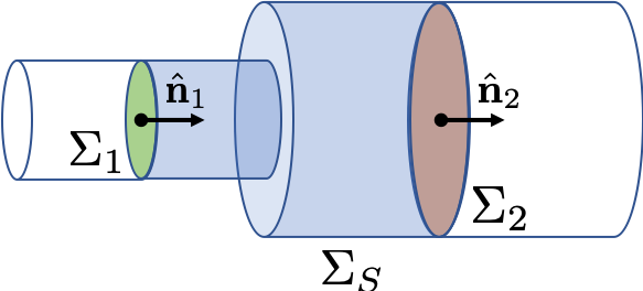
In the following, we turn this property into a strategy for enhancing the electric field in high-index resonators. Let us consider a closed surface , which is the union of three sections , , such that , as sketched in Fig.1. is a portion of the physical resonator boundary , where the normal component of the current density vanishes, while and are purely mathematical surfaces contained in the interior of , with normal unit vector and and surface areas and . Therefore, we have that the flux of the displacement current is conserved
| (7) |
Eq. 7 holds for any mode of any high-index resonator. We now make the additional assumption that there exists a density current mode, e.g. , which is directed along and on the surfaces and , respectively
| (8) |
and we also assume that the corresponding flux is non-vanishing. In the next section, we show that a high-index ring resonator exhibits topologically protected modes satisfying these hypotheses. By using Eq. 8 in Eq. 7 we obtain:
| (9) |
where is the average of on . By combining Eqs. 6 with Eq. 9, we directly obtain that
| (10) |
where is the average of the electric field on . Equation 10 is the central result of this paper and constitutes a general principle to achieve high field enhancement in high-index resonators. By squeezing the section of the resonator, as schematized in Fig. 2c, the average electric field of the mode increases to keep the flux constant, counterbalancing the reduction of the surface area.
0.1 Magnetoquasistatic modes
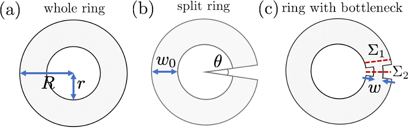
Looking for a mode that could be a suitable candidate for the application of the flux-conservation design principle, we investigate the magnetoquasistatic modes of a dielectric ring. Dielectric ring resonators have been recently studied experimentally by Zenin et al. to control scattering directionality 40. Here, we investigate the ring sketched in Fig. 2a with minor radius , major radius , with , corresponding width , and a thickness . To simplify our analysis, and only within the current subsection, we make the additional assumption that the ring has thickness much smaller than : under this hypothesis we can use the approximated method introduced in Ref. 41 to calculate the magnetoquasistatic modes of the ring, instead of the three-dimensional but more computationally intensive method presented in 22.
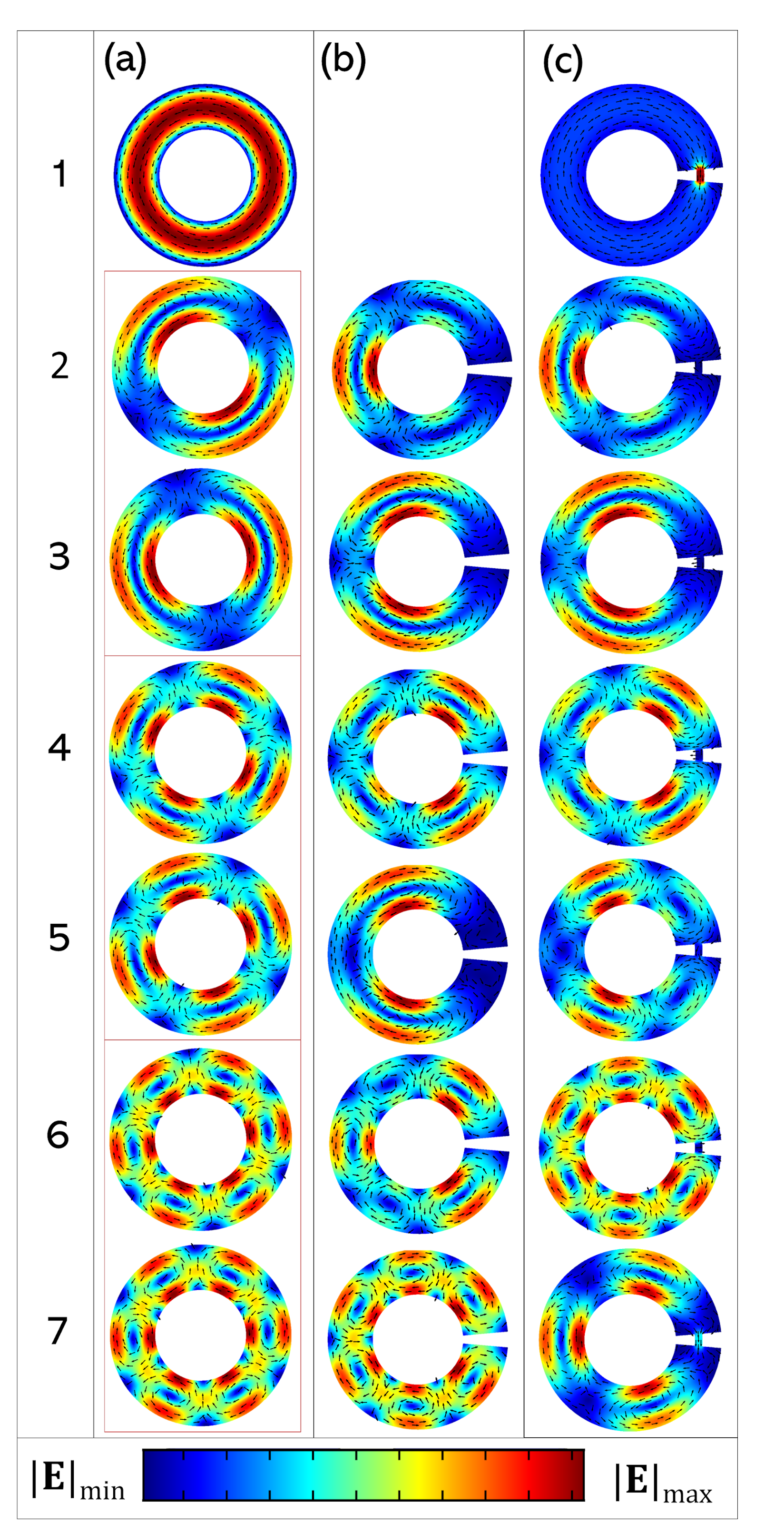
The first seven modes exhibited by the ring resonator are shown in Figure 3a, which are are independent of as long as . The fundamental mode is a displacement current loop circulating along the toroidal direction, shown at the top of Fig. 3a. The next modes exhibit two or more counter-rotating loops of current density field, corresponding to counter-directed magnetic dipole moments.
The mode fulfills all the requirements needed of the flux-conservation design principle since i) the current density is always directed along the toroidal direction and ii) the associated flux is non-vanishing. In particular, on the two sections and the displacement current density is directed along the corresponding normal unit vector and , respectively. Instead, the high-order modes shown in Fig. 3a exhibit a vanishing flux at any section of the ring, and are not useful for our goals.
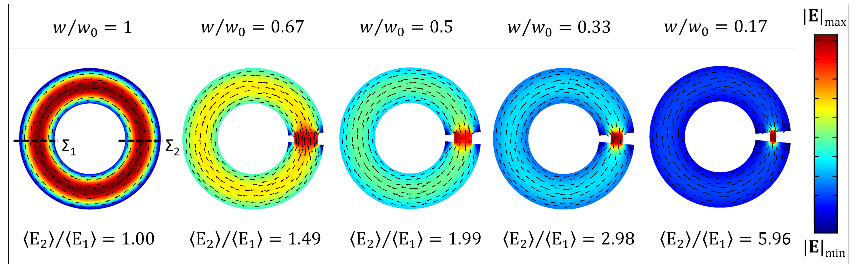
Thus, we introduce a bottleneck of width w in the ring in correspondence of the angular sector of aperture , as shown in Fig. 2b, investigating in Fig. 4 the change in the fundamental magnetoquasistatic mode as the bottleneck reduces. As long as the width w of the bottleneck remains finite, the topology of the domain preserves the existence of the current-loop mode. Moreover, as the width w is reduced, the amplitude of the displacement current density is enhanced within the bottleneck to keep the flux of constant.
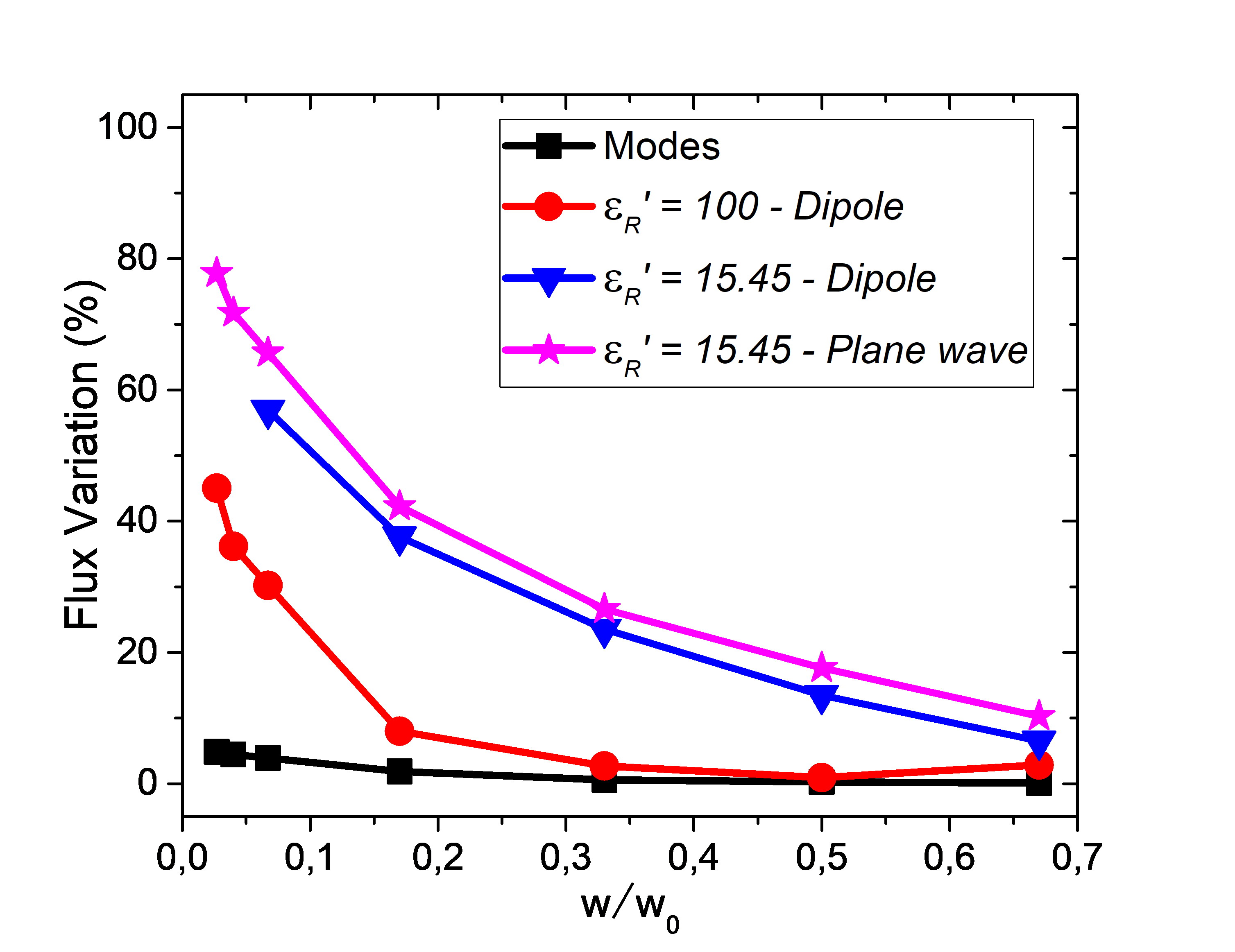
To support this claim, in Fig. 5 we show with a black line the relative variation of the flux of the displacement current density between the two sections and , defined in Fig. 2, as a function of . In the investigated range, the flux variation, is lower than , confirming our design principle.
Figure 3c shows the first magnetoquasistatic modes of the ring with the bottleneck of width . The higher-order modes are only slightly affected by the introduction of the bottleneck. Specifically, the symmetry breaking lifts the degeneracy of the modes , , of the whole ring, but since the net-flux of the displacement current through any section of the ring is zero, we do not observe any field localization.
To further underline the role played by the topology of the resonator geometry, we also show in Figure 3b the magnetoquasistatic modes of a split ring resonator. The displacement current density loop embracing the whole structure does not exist in this case, due to the different topology (genus) of the object. The remaining modes are similar to the corresponding modes of a whole ring, and thus are less affected by the change in the topology of the structure.
0.2 Full-wave analysis
So far, we have investigated how to apply the flux-conservation design principle to the magnetoquasistatic modes of the ring resonators, which were inherently independent of the excitation conditions. In this section, guided by the previous modal analysis, we turn to the solution of the full-wave 3D scattering problem in the presence of an external excitation using finite-element-method simulations, carried out in COMSOL Multiphysics.
It is important to point out that a plane wave, linearly polarized in the plane of the ring and propagating orthogonally to it, is not able to excite the fundamental loop of the displacement current density. Nevertheless, such a mode can be excited by a plane wave propagating within the plane of the ring, or an electric dipole located in proximity of the ring. A dipolar excitation may model an emitting molecule, a quantum dot, or metal nanoparticle located nearby. In the following, we consider a dipole excitation, while the analysis carried out for a plane wave excitation has been reported in the SI.
In Figure 6, we investigate high-index ring resonators with high relative permittivity . The ring resonator has rectangular cross section, with minor radius , major radius and thickness , centered in the origin of a Cartesian coordinate system with its flat faces parallel to the plane. In all the investigated cases, to improve numerical convergence, we introduced a smoothing of the bottleneck corners (fillet) with curvature radius of .
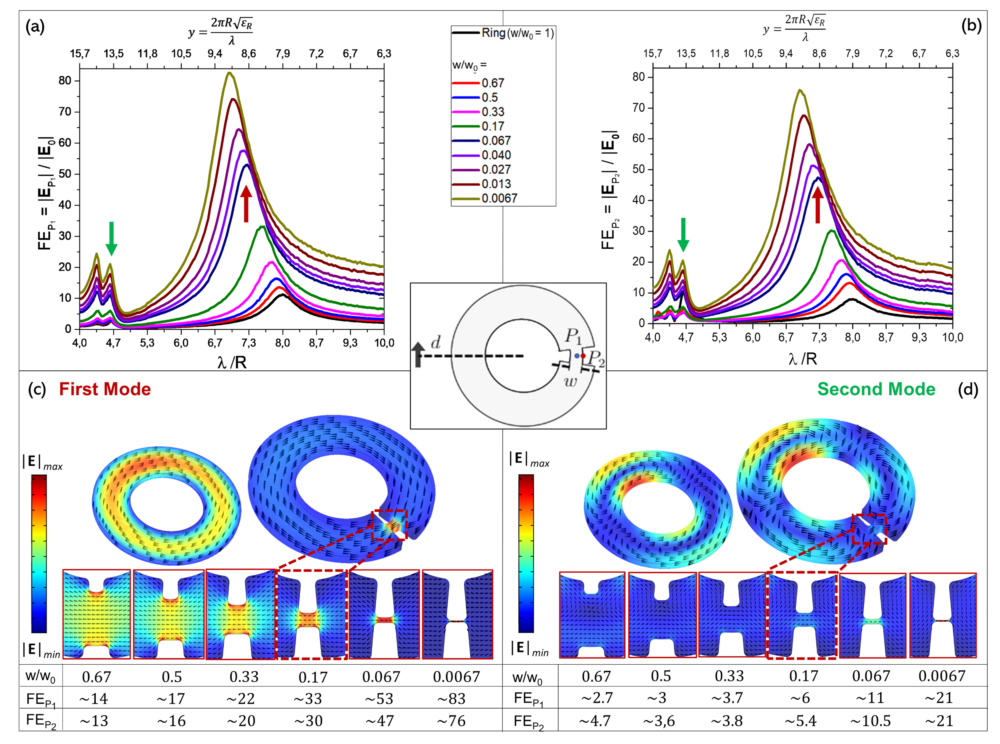
We investigate the field enhancement by varying the bottleneck width . The total electric field is probed at the two different points shown in the inset: the point is located within the dielectric region in the middle of the bottleneck , the point is located in the air just outside the boundary of the resonator . In the same two points, we also calculate the electric field generated by the exciting dipole, when it is free-standing, namely in the absence of the dielectric object. The electric field enhancement FE is defined as the ratio of these two quantities:
| (11) |
We show the field enhancement as a function of the free-space wavelength for several relative bottleneck widths at (Fig. 6a) and at (Fig. 6b). In both cases, the FE spectrum of the whole ring resonator () is also shown for comparison. Since the electric fields of the fundamental mode is tangent to the boundary of the ring, and the tangential component of the electric field are always conserved, the electric field enhancement values in in Fig. 6b are roughly the same as the values in Fig. 6a. As we reduce the bottleneck width , the peak value of field enhancement increases from for , to for . The electric field localization within the bottleneck is shown in Figure 6c in correspondence of several ratios .
To quantify the validity of the flux-conservation principle, we show in Fig. 5 the variation of the flux of the electric field between the cross sections and of the ring, as defined in Fig. 2c. Differently from what was done in the previous section, here the analysis is performed on the state of the electric field, and not on the modes. As long as the flux undergoes a variation of less than . Significant violations of the flux conservation happen only for values of less than .
In Fig. S2 of the Supporting Information, we also investigate the spatial decay of the field enhancement in the external region (air) as a function of the distance from the resonator’s walls, concluding that the field enhancement supported by this platform are easily accessible outside the resonator.
The second peak at higher frequencies in Figure 6a-b is caused by the second mode of the ring with bottleneck, shown in Fig. 3c. This mode exhibits vanishing flux at any section of the ring, therefore flux-conservation does not imply field enhancement, which in facts is significantly lower compared to the first peak. Consistently, the field distributions do not exhibit localization within the bottleneck, as shown in Figure 6d. Appreciable FE values at the second peak are only obtained when the ratio reaches very low values (less than ), due to a spectral overlap with the fundamental mode.
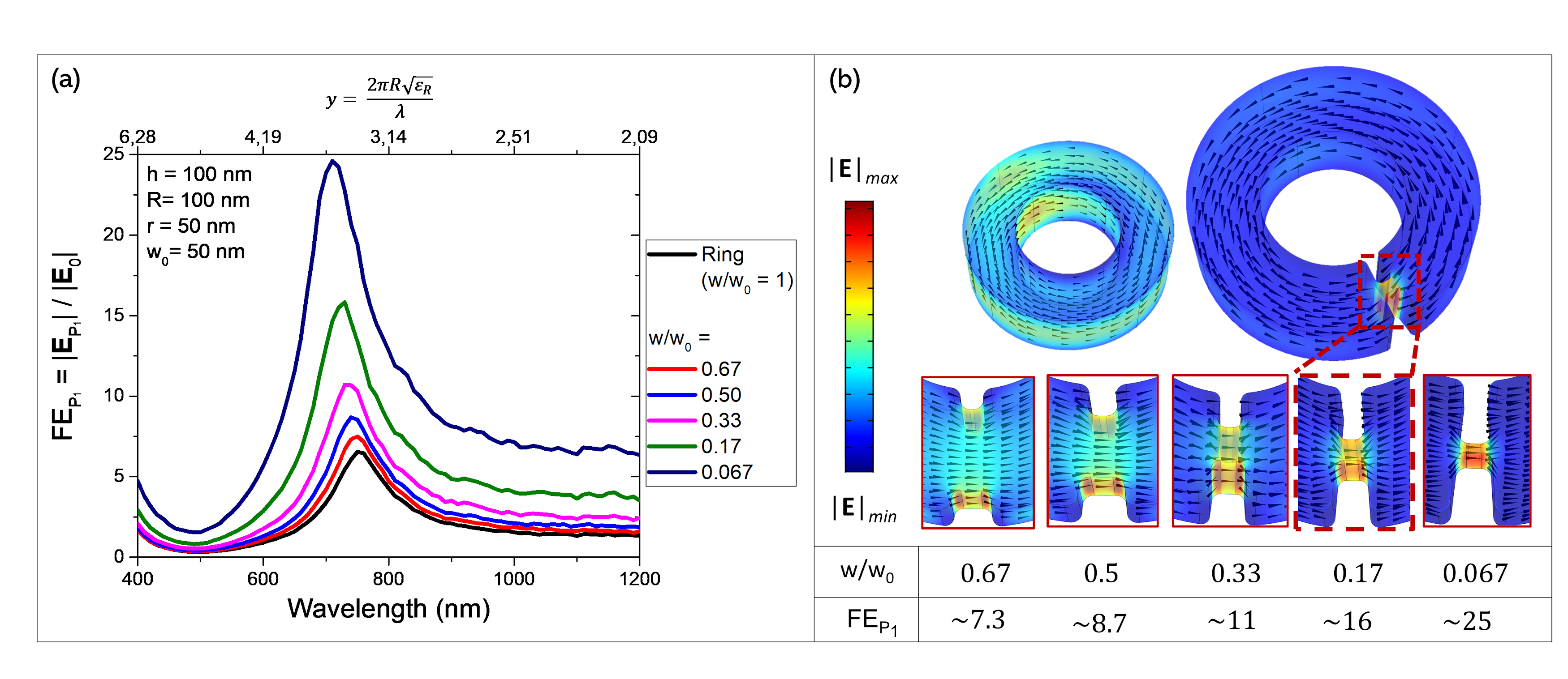
However, although permittivities of values 100 and higher are routinely available at microwaves frequencies for several applications including filters, resonators and antennas42, 43, 44, 45, in the visible or near infrared only materials with moderate permittivities, such as Silicon or GaAs are currently available. In the following, we consider silicon rings, with . The ring resonator has major radius nm, minor radius , thickness nm, and different bottleneck widths . In this case, the hypotheses behind the magnetoquasistatic approximation are not fully verified.
It is immediately apparent that the values of field enhancement reached by introducing a bottleneck in the silicon ring are lower if compared to high-index materials, as shown in figure 7a. For instance, the field enhancement FE obtained for is about , compared to about achieved for the investigated high-index resonator. This is because, for objects of moderate permittivities, the hypotheses behind the magnetoquasistatic approximation are not fully verified, and a non-vanishing normal component of the displacement current density to the boundary of the particle arises, causing a dispersion of the flux and a consequent reduction of the maximum achievable field enhancement. This is confirmed by looking at the variation of the flux between the sections and of the ring in Fig. 5. For a bottleneck of width , about of the flux is dispersed. Comparable values of field enhancement and similar considerations for the flux dispersion also hold for a silicon ring excited by a plane wave propagating in the plane of the ring, investigated in Fig. S5 of the Supporting Information. Nevertheless, the values of electric field enhancement are still very significant and comparable in magnitude to alternative state-of-the-art approaches based on electric toroidal dipole resonances 31.
1 Conclusions
In this letter, we introduced a design principle to localize and enhance electric fields in high/moderate-index resonators, based on the flux conservation of the displacement current density. We apply this design principle to a high-index ring resonator, showing that by squeezing its section through the introduction of a bottleneck, the electric field in correspondence of the bottleneck is increasingly enhanced as the width is reduced to keep the flux constant. Furthermore, due to the boundary conditions, the enhancement of the field is achieved in both the internal and external regions. Then, we also apply this principle to a moderate-index dielectric resonator, where the hypotheses behind the magnetoquasistatic approximation are only partially verified. Even though the achieved enhancement is reduced with respect to the previous ideal case, it is still very significant and comparable in magnitude to alternative state-of-the-art approaches based on electric toroidal dipole resonances. The introduced design principle, validated here in its simplest form, may constitute the first step into the engineering of the displacement current density, guiding the design of the topology and the geometry of complex dielectric structures to funnel light at will.
The Supporting Information is available free of charge on the ACSPublications website at DOI: In Fig S1 we carry out the comparison between the high-index ring with a bottleneck and the split-ring in the presence of a dipole excitation. In Fig. S2, we investigate the spatial decay of the field enhancement in the external region (air) of a high-index ring with bottleneck as a function of the distance from the resonator’s walls. In Fig. S3, the field enhancement in a Si ring resonator with a dipole excitation a function of its thickness, achieving field enhancement greater than . In Fig. S4, a Si ring resonator has been designed to operate in the near-infrared. In Fig. S5 a silicon ring with a bottleneck is excited by a plane wave propagating in the plane of the ring.
References
- Novotny and Hecht 2014 V. Novotny, L; and Hecht, B. Principles of nano-optics; Cambridge university press, 2012
- Fredkin and Mayergoyz 2003 Fredkin, D. R.; Mayergoyz, I. D. Resonant Behavior of Dielectric Objects (Electrostatic Resonances). Phys. Rev. Lett. 2003, 91, 253902
- Bergman and Stockman 2003 Bergman, D. J.; Stockman, M. I. Surface Plasmon Amplification by Stimulated Emission of Radiation: Quantum Generation of Coherent Surface Plasmons in Nanosystems. Phys. Rev. Lett. 2003, 90, 027402
- Li et al. 2003 Li, K.; Stockman, M. I.; Bergman, D. J. Self-Similar Chain of Metal Nanospheres as an Efficient Nanolens. Phys. Rev. Lett. 2003, 91, 227402
- Wang and Shen 2006 Wang, F.; Shen, Y. R. General Properties of Local Plasmons in Metal Nanostructures. Phys. Rev. Lett. 2006, 97, 206806
- Klimov 2014 Klimov, V. Nanoplasmonics; CRC press, 2014
- Schuller et al. 2010 Schuller, J. A.; Barnard, E. S.; Cai, W.; Jun, Y. C.; White, J. S.; Brongersma, M. L. Plasmonics for extreme light concentration and manipulation. Nature materials 2010, 9, 193–204
- Forestiere et al. 2012 Forestiere, C.; Pasquale, A. J.; Capretti, A.; Miano, G.; Tamburrino, A.; Lee, S. Y.; Reinhard, B. M.; Dal Negro, L. Genetically Engineered Plasmonic Nanoarrays. Nano Letters 2012, 12, 2037–2044, PMID: 22381056
- Khurgin 2015 Khurgin, J. B. How to deal with the loss in plasmonics and metamaterials. Nature Nanotechnology 2015, 10, 2–6
- García-Etxarri et al. 2011 García-Etxarri, A.; Gómez-Medina, R.; Froufe-Pérez, L. S.; López, C.; Chantada, L.; Scheffold, F.; Aizpurua, J.; Nieto-Vesperinas, M.; Sáenz, J. J. Strong magnetic response of submicron silicon particles in the infrared. Optics express 2011, 19, 4815–4826
- Evlyukhin et al. 2012 Evlyukhin, A. B.; Novikov, S. M.; Zywietz, U.; Eriksen, R. L.; Reinhardt, C.; Bozhevolnyi, S. I.; Chichkov, B. N. Demonstration of Magnetic Dipole Resonances of Dielectric Nanospheres in the Visible Region. Nano Letters 2012, 12, 3749–3755, PMID: 22703443
- Kuznetsov et al. 2012 Kuznetsov, A. I.; Miroshnichenko, A. E.; Fu, Y. H.; Zhang, J.; Luk’Yanchuk, B. Magnetic light. Scientific reports 2012, 2, 492
- Kuznetsov et al. 2016 Kuznetsov, A. I.; Miroshnichenko, A. E.; Brongersma, M. L.; Kivshar, Y. S.; Luk’yanchuk, B. Optically resonant dielectric nanostructures. Science 2016, 354
- Rybin et al. 2017 Rybin, M. V.; Koshelev, K. L.; Sadrieva, Z. F.; Samusev, K. B.; Bogdanov, A. A.; Limonov, M. F.; Kivshar, Y. S. High- Supercavity Modes in Subwavelength Dielectric Resonators. Phys. Rev. Lett. 2017, 119, 243901
- Jahani and Jacob 2016 Jahani, S.; Jacob, Z. All-dielectric metamaterials. Nature nanotechnology 2016, 11, 23
- Yavas et al. 2017 Yavas, O.; Svedendahl, M.; Dobosz, P.; Sanz, V.; Quidant, R. On-a-chip biosensing based on all-dielectric nanoresonators. Nano letters 2017, 17, 4421–4426
- Yavas et al. 2019 Yavas, O.; Svedendahl, M.; Quidant, R. Unravelling the Role of Electric and Magnetic Dipoles in Biosensing with Si Nanoresonators. ACS nano 2019, 13, 4582–4588
- Hanifeh et al. 2019 Hanifeh, M.; Albooyeh, M.; Capolino, F. Helicity Maximization Below the Diffraction Limit. 2019 arXiv:1906.07170
- Graf et al. 2019 Graf, F.; Feis, J.; Garcia-Santiago, X.; Wegener, M.; Rockstuhl, C.; Fernandez-Corbaton, I. Achiral, Helicity Preserving, and Resonant Structures for Enhanced Sensing of Chiral Molecules. ACS Photonics 2019, 6, 482–491
- Mohammadi et al. 2019 Mohammadi, E.; Tavakoli, A.; Dehkhoda, P.; Jahani, Y.; Tsakmakidis, K. L.; Tittl, A.; Altug, H. Accessible superchiral near-fields driven by tailored electric and magnetic resonances in all-dielectric nanostructures. ACS Photonics 2019, 6, 1939–1946
- Garcia-Guirado et al. 2019 Garcia-Guirado, J.; Svedendahl, M.; Puigdollers, J.; Quidant, R. Enhanced chiral sensing with dielectric nano-resonators. Nano Letters 2019,
- Forestiere et al. 2020 Forestiere, C.; Miano, G.; Rubinacci, G.; Pascale, M.; Tamburrino, A.; Tricarico, R.; Ventre, S. Magnetoquasistatic resonances of small dielectric objects. Phys. Rev. Research 2020, 2, 013158
- Luk’yanchuk et al. 2017 Luk’yanchuk, B.; Paniagua-Domínguez, R.; Kuznetsov, A. I.; Miroshnichenko, A. E.; Kivshar, Y. S. Hybrid anapole modes of high-index dielectric nanoparticles. Physical Review A 2017, 95, 063820
- Wang et al. 2019 Wang, W.; Zhao, X.; Xiong, L.; Zheng, L.; Shi, Y.; Liu, Y.; Qi, J. Broken symmetry theta-shaped dielectric arrays for a high Q-factor Fano resonance with anapole excitation and magnetic field tunability. OSA Continuum 2019, 2, 507–517
- Mignuzzi et al. 2019 Mignuzzi, S.; Vezzoli, S.; Horsley, S. A. R.; Barnes, W. L.; Maier, S. A.; Sapienza, R. Nanoscale Design of the Local Density of Optical States. Nano Letters 2019, 19, 1613–1617, PMID: 30786717
- Kapitanova et al. 2017 Kapitanova, P.; Ternovski, V.; Miroshnichenko, A.; Pavlov, N.; Belov, P.; Kivshar, Y.; Tribelsky, M. Giant field enhancement in high-index dielectric subwavelength particles. Scientific reports 2017, 7, 1–8
- Grinblat et al. 2016 Grinblat, G.; Li, Y.; Nielsen, M. P.; Oulton, R. F.; Maier, S. A. Enhanced third harmonic generation in single germanium nanodisks excited at the anapole mode. Nano letters 2016, 16, 4635–4640
- Ghirardini et al. 2018 Ghirardini, L.; Marino, G.; Gili, V. F.; Favero, I.; Rocco, D.; Carletti, L.; Locatelli, A.; De Angelis, C.; Finazzi, M.; Celebrano, M.; Neshev, D. N.; Leo, G. Shaping the Nonlinear Emission Pattern of a Dielectric Nanoantenna by Integrated Holographic Gratings. Nano Letters 2018, 18, 6750–6755, PMID: 30277790
- Carletti et al. 2018 Carletti, L.; Marino, G.; Ghirardini, L.; Gili, V. F.; Rocco, D.; Favero, I.; Locatelli, A.; Zayats, A. V.; Celebrano, M.; Finazzi, M.; Leo, G.; De Angelis, C.; Neshev, D. N. Nonlinear Goniometry by Second-Harmonic Generation in AlGaAs Nanoantennas. ACS Photonics 2018, 5, 4386–4392
- Koshelev et al. 2020 Koshelev, K.; Kruk, S.; Melik-Gaykazyan, E.; Choi, J.-H.; Bogdanov, A.; Park, H.-G.; Kivshar, Y. Subwavelength dielectric resonators for nonlinear nanophotonics. Science 2020, 367, 288–292
- Yang et al. 2018 Yang, Y.; Zenin, V. A.; Bozhevolnyi, S. I. Anapole-Assisted Strong Field Enhancement in Individual All-Dielectric Nanostructures. ACS Photonics 2018, 5, 1960–1966
- Robinson et al. 2005 Robinson, J. T.; Manolatou, C.; Chen, L.; Lipson, M. Ultrasmall mode volumes in dielectric optical microcavities. Physical review letters 2005, 95, 143901
- Engheta 2007 Engheta, N. Circuits with light at nanoscales: optical nanocircuits inspired by metamaterials. Science 2007, 317, 1698–1702
- Li et al. 2013 Li, Y.; Su, L.; Shou, C.; Yu, C.; Deng, J.; Fang, Y. Surface-enhanced molecular spectroscopy (SEMS) based on perfect-absorber metamaterials in the mid-infrared. Scientific reports 2013, 3, 1–8
- Tapar et al. 2020 Tapar, J.; Kishen, S.; Prashant, K.; Nayak, K.; Emani, N. K. Enhancement of the optical gain in GaAs nanocylinders for nanophotonic applications. Journal of Applied Physics 2020, 127, 153102
- Caldarola et al. 2015 Caldarola, M.; Albella, P.; Cortés, E.; Rahmani, M.; Roschuk, T.; Grinblat, G.; Oulton, R. F.; Bragas, A. V.; Maier, S. A. Non-plasmonic nanoantennas for surface enhanced spectroscopies with ultra-low heat conversion. Nature communications 2015, 6, 1–8
- Pryce et al. 2011 Pryce, I. M.; Kelaita, Y. A.; Aydin, K.; Atwater, H. A. Compliant metamaterials for resonantly enhanced infrared absorption spectroscopy and refractive index sensing. ACS nano 2011, 5, 8167–8174
- Bontempi et al. 2017 Bontempi, N.; Chong, K. E.; Orton, H. W.; Staude, I.; Choi, D.-Y.; Alessandri, I.; Kivshar, Y. S.; Neshev, D. N. Highly sensitive biosensors based on all-dielectric nanoresonators. Nanoscale 2017, 9, 4972–4980
- Forestiere et al. 2020 Forestiere, C.; Miano, G.; Rubinacci, G. Resonance frequency and radiative Q-factor of plasmonic and dielectric modes of small objects. arXiv:2005.05706 2020
- Zenin et al. 2020 Zenin, V.; Garcia-Ortiz, C.; Evlyukhin, A.; Yang, Y.; Malureanu, R.; Novikov, S.; Coello, V.; Chichkov, B.; Bozhevolnyi, S.; Lavrinenko, A.; Mortensen, N. Engineering nanoparticles with pure high-order multipole scattering. A C S Photonics 2020, 7, 1067–1075
- Forestiere et al. 2019 Forestiere, C.; Gravina, G.; Miano, G.; Pascale, M.; Tricarico, R. Electromagnetic modes and resonances of two-dimensional bodies. Physical Review B 2019, 99, 155423
- Richtmyer 1939 Richtmyer, R. Dielectric resonators. Journal of Applied Physics 1939, 10, 391–398
- Kajfez et al. 1998 Kajfez, D.; Guillon, P., et al. Dielectric resonators; Noble Publishing Corporation Atlanta, 1998
- Long et al. 1983 Long, S.; McAllister, M.; Liang Shen, The resonant cylindrical dielectric cavity antenna. IEEE Transactions on Antennas and Propagation 1983, 31, 406–412
- Mongia and Bhartia 1994 Mongia, R. K.; Bhartia, P. Dielectric resonator antennas—a review and general design relations for resonant frequency and bandwidth. International Journal of Microwave and Millimeter-Wave Computer-Aided Engineering 1994, 4, 230–247