Strong Optomechanical Coupling at Room Temperature by Coherent Scattering
Abstract
Abstract Quantum control of a system requires the manipulation of quantum states faster than any decoherence rate. For mesoscopic systems, this has so far only been reached by few cryogenic systems. An important milestone towards quantum control is the so-called strong coupling regime, which in cavity optomechanics corresponds to an optomechanical coupling strength larger than cavity decay rate and mechanical damping. Here, we demonstrate the strong coupling regime at room temperature between a levitated silica particle and a high finesse optical cavity. Normal mode splitting is achieved by employing coherent scattering, instead of directly driving the cavity. The coupling strength achieved here approaches three times the cavity linewidth, crossing deep into the strong coupling regime. Entering the strong coupling regime is an essential step towards quantum control with mesoscopic objects at room temperature.
Introduction
Laser cooling has revolutionised our understanding of atoms, ions and molecules.
Lately, after a decade of experimental and theoretical efforts employing the same techniques [1, 2, 3, 4, 5, 6, 7, 8], the motional ground state of levitated silica nanoparticles at room temperature has been reported [9].
While this represents an important milestone towards the creation of mesoscopic quantum objects, coherent quantum control of levitated nanoparticles [10, 11] still remains elusive.
Levitated particles stand out among the plethora of optomechanical systems [12] due to their detachment, and therefore high degree of isolation from the environment. Their centre of mass, rotational and vibrational degrees of freedom [13] make them attractive tools for inertial sensing [14], rotational dynamics [15, 16, 17, 18], free fall experiments [19], exploration of dynamic potentials [20], and are envisioned for testing macroscopic quantum phenomena at room temperature [21, 22, 2, 10].
Recently, the centre-of-mass motion of a levitated particle has successfully been 3D cooled employing coherent scattering (CS) [23, 8]. Cooling with CS is less sensitive to phase noise heating than actively driving the cavity [7, 24], because optimal coupling takes place at the intensity node. Lately, this has enabled phonon occupation numbers of less than one [9].
For controlled quantum experiments, such as the preparation of non-classical, squeezed [25, 26] or entangled states [27, 28], the particle’s motional state needs to be manipulated faster than the absorption of a single phonon from the environment. A valuable but less stringent condition is the so-called strong coupling regime (SCR), where the optomechanical coupling strength between the mechanical motion of a particle and an external optical cavity exceeds the particle’s mechanical damping and the cavity linewidth (). The SCR presents one of the first stepping stones towards full quantum control and has been demonstrated in opto- and electromechanical systems [29, 30, 31], followed by quantum-coherent control [32].
Here, we observe normal mode splitting (NMS) in SCR with levitated nanoparticles [33], as originally reported in atoms [34]. In contrast to previous experiments, we employ CS [35, 36, 23, 8].
Our table top experiment offers numerous ways to tune the optomechanical coupling strength at room temperature, a working regime that is otherwise nearly exclusive to plasmonic nanocavities [37, 38].
Results
Experimental Setup for Levitation
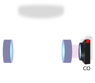
Our experimental setup is displayed in Fig.1. A silica nanoparticle (green) of radius nm, mass kg and refractive index is placed in a cavity (purple) by an optical tweezers trap (yellow) with wavelength , power , numerical aperture , and optical axis () perpendicular to the cavity axis (). The trap is linearly polarised along the axis defined as (see inset in Fig.1).
The nanoparticle’s eigenfrequencies are non-degenerate due to tight focusing. The trap is mounted on a nano-positioning stage allowing for precise 3D placement of the particle inside the low loss, high finesse Fabry-Pérot cavity with a cavity linewidth kHz, cavity finesse and free spectral range GHz. The relative detuning between the trap and the cavity resonance is tunable. The intracavity photon number is estimated from the transmitted cavity power (CO in Fig.1), and the particle position displacement is measured by interfering the scattered light with a co-propagating reference beam [39]. In CS, scattering events from the detuned trapping field, locked at , populate the cavity. This contrasts the approach of actively driving the cavity [3, 7, 24].
A particle in free space, solely interacting with the trapping light, Raman scatters photons into free space and the energy difference between incident and emitted light equals with m=x,y,z. In this case photon up and down conversion are equally probable [40].
The presence of an optical cavity alters the density of states of electromagnetic modes and enhances the CS into the cavity modes through the Purcell effect. If trap photons are red (blue) detuned with respect to the cavity resonance, the cavity enhances photon up (down) conversion and net cooling (heating) takes place.
Coherent Scattering Theory In order to estimate the corresponding optomechanical coupling strength in CS, we follow [36]. The interaction Hamiltonian for a polarizable particle interacting with an electric field is given by with the particle polarizability and vacuum permittivity . The total electric field consists of the trap (), cavity () and free space electromagnetic modes () yielding the interaction Hamiltonian
| (1) | |||||
| (2) |
where and are only populated by scattering events from the particle ( with () being the number of trap (cavity) photons). As can be seen from Eq. 1, the interaction Hamiltonian consists of six terms of which only the two terms proportional to and are relevant for the following discussion [36]. The former one gives rise to the optomechanical coupling by CS, and the latter to the coupling achieved by actively driving the cavity. The term gives rise to the trapping potential, while the term causes recoil heating [41, 36], which can be neglected for the moderate vacuum conditions presented here [41, 7]. The remaining two terms can be safely neglected according to [36].
In the following, we use the simplified interaction Hamiltonian given by Eq.2 where we separate the parts contributing to the optomechanical coupling due to CS , active driving , and population of the intracavity field (see Methods .2).
For the measurements presented here, the trap is -polarised with (see inset Fig.1). This simplifies to
where () is the photon annihilation (creation) operator and () is the phonon annihilation (creation) operator.
The CS optomechanical coupling strengths are
| (3) |
with cavity wavevector , zero-point fluctuations and , with being the particle position along the cavity axis and corresponding to the intensity minimum.
The optical cavity resonance frequency shift caused by a particle located at maximum intensity of the intracavity standing wave is
with cavity mode volume , cavity waist , cavity length , and . The trap electric field is with trap waists and .
Due to the intracavity standing wave, the optomechanical coupling strength has a sinusoidal dependence on with opposite phase for and . In contrast, if .
For clarity, we limit the discussion to coupling along the cavity axis (y), such that and . Similar results can be obtained for the other directions with the same level of control.
The maximum expected coupling strength from CS is for our parameters. However, we displace the particle by from the cavity centre for better experimental stability. Hence, our expected optomechanical coupling strength is reduced by down to , enabling the SCR with . Despite the fact that this value is a factor of lower than previously reported [9], the deep SRC with remains unaccomplished.
Transition to the Strong coupling regime In the weak coupling regime , the Lorentzian shaped spectra of our mechanical oscillator displays a single peak at its resonance frequency . When increases, the energy exchange rate between optical and mechanical mode grows until the SCR is reached at [33]. In the SCR, the optical and mechanical mode hybridise, which gives rise to two new eigenmodes at shifted eigenfrequencies (see Eq.9). At this point the energy exchange in between the optical and mechanical mode is faster than the decoherence rate of each individual mode. The hybridized eigenmode frequencies
| (4) |
experience an avoided crossing, the so-called NMS, which reaches a maximum of at the optimal detuning . The linewidth of the hybrid modes at this detuning is . Therefore, needs to be smaller or comparable to to resolve the NMS of .
As can be seen from Eq.3, we control through various parameters like the trap power , the particle position and the polarisation angle . The optical coupling rate depends additionally on the trap detuning and is maximised at to [12, 7]. While and only influence the magnitude of the coupling strength, and change also the nature of the coupling from 1D to potentially 3D [36]. For simplicity, we focus on varying and in the following measurements and keep , , and kHz, corresponding to mBar, fixed (see Methods .1).
The range of is limited due to instabilities in the experiment.
Observation of Strong Coupling
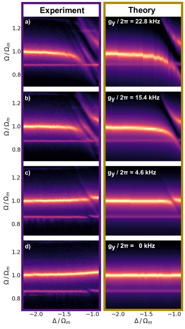
Fig.2 left panel displays the experimental position power spectral density (PSD) versus for different .
Throughout the remaining part of the manuscript, we fit our PSD to Eq.9, if not stated differently. From this fit, we can extract the hybridized modes that are separated by .
We cover a total distance of and change the optomechanical coupling strength, and therefore also the NMS, from (a) , (b) , (c) and (d) , exploring the entire range from strong coupling to zero coupling. The right panel shows the fit, which is in good agreement with the data. We observe two eigenmodes with an exceptional NMS of at , corresponding to 20% of the bare mechanical eigenfrequency, once the system enters the SCR at [33]. For , we observe only the mechanical mode with slightly increased frequency due to the additional trapping potential supplied by the cavity field (see Fig.2(d)). In Fig.2(a) and (b) we observe an additional NMS in the -mode, which stems from a second cross polarised optical mode. Note that, throughout all our measurements (see Fig.2-Fig.4), the second NMS is the largest source for discrepancies between experiment and theory (for more details see Supplementary Information). We also attribute the NMS of the -mode at to the second optical mode as observed in Fig.2(d), since the -mode should be decoupled from the first mode ( if ).
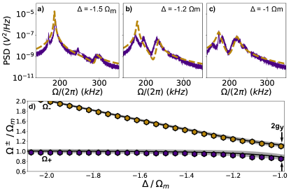
Fig.3(a)-(c) displays the particle’s position PSD at different while it is located at the intensity minimum, corresponding to the position of maximum coupling , displayed in Fig.2(a). Our theory (yellow) captures the data (purple) well. In Fig.3(a) the optical mode and mechancial mode begin to hybridise into new eigenmodes at which is confirmed by a second peak appearing at kHz. The hybridization becomes stronger as approaches the cavity resonance and the NMS is maximized at as shown in Fig.3(c). The dependence of the new eigenmodes on is shown in Fig.3(d), displaying clearly the expected avoided crossing of . The solid line is a fit to Eq.4. The edges of the shaded area represent the upper and lower limit of the fit, which we obtain by fitting only the upper branch (yellow) or the lower branch (purple), respectively.
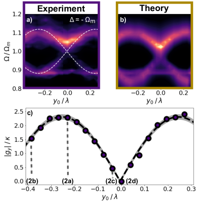
As already discussed previously, our experiment allows to change the optomechanical coupling by changing various experimental parameters, which stands in contrast to many other experimental platforms. Fig.4 displays this flexibility to reach the SCR by demonstrating the position dependence of at optimal detuning extracted from the data Fig.2(a)-(d). The experimental and theoretical position PSDs versus are depicted in Fig.4(a) and (b).The mode at corresponds to the decoupled -mode. The dashed line highlights the theoretical frequency of the eigenmodes following Eq.4. In both experiment and theory we observe the expected sinusoidal behaviour predicted by Eq.3. Fig.4(c) depicts (circles) extracted from Fig.4(a). The dashed line represents the fit to the absolute value of Eq.3 yielding kHz which coincides well with the theoretical value of kHz. The measured period coincides with the expected period of . The shaded area corresponds to 3 of the fit.
Discussion
As a figure of merit to assess the potential of our system for quantum applications, we use the quantum cooperativity, which yields here at a pressure mbar and promises a value as large as at mbar, since . At this low pressure, the photon recoil heating rate [41] equals our mechanical decoherence rate , and therefore halves the reachable . The maximum is ultimately limited by , regardless if we reduce the pressure even further. Nevertheless, this predicted value of is many orders of magnitude larger than what has been achieved in levitation setups by actively driving the cavity [7, 24] and larger than achieved in [9]. More importantly it enables coherent quantum control at at pressure levels mbar, a pressure regime commonly demonstrated in numerous levitation experiments [41, 7, 9].
Furthermore, our experimental parameters promise the possibility of motional ground state cooling in our system [9], which in combination with coherent quantum control enables us to fully enter the quantum regime with levitated systems and to create non-classical states of motion and superposition states of macroscopic objects in free fall experiments [10, 11] in the future.
Data availability. The data that support the findings of this study are available from the corresponding author upon request.
Acknowledgments. The authors thank J. Gieseler and C. González-Ballestero for stimulating discussions. The project acknowledges financial support from the European Research Council through grant QnanoMECA (CoG - 64790), Fundació Privada Cellex, CERCA Programme / Generalitat de Catalunya, and the Spanish Ministry of Economy and Competitiveness through the Severo Ochoa Programme for Centres of Excellence in RD (SEV-2015-0522). This project has received funding from the European Union’s Horizon 2020 research and innovation programme under the Marie Skłodowska-Curie grant agreement No 713729.
Authors contribution
A.D.L.R.S. performed the measurements, N.M. evaluated the data and wrote the manuscript, R.Q supervised the study.
References
- [1] Chang, D. E. et al. Cavity opto-mechanics using an optically levitated nanosphere. PNAS 07, 1005–1010 (2010).
- [2] Romero-Isart, O., Juan, M. L., Quidant, R. & Cirac, J. I. Toward quantum superposition of living organisms. New Journal of Physics 12, 033015 (2010).
- [3] Kiesel, N. et al. Cavity cooling of an optically levitated submicron particle. PNAS 110, 35 (2013).
- [4] Asenbaum, P., Kuhn, S., Nimmrichter, S., Sezer, U. & Arndt, M. Cavity cooling of free silicon nanoparticles in high vacuum. Nature Communications 4, 2743 (2013).
- [5] Millen, J., Fonseca, P. Z. G., Mavrogordatos, T., Monteiro, T. S. & Barker, P. F. Cavity Cooling a Single Charged Levitated Nanosphere. Physical Review Letters 114, 123602 (2015).
- [6] Fonseca, P. Z. G., Aranas, E. B., Millen, J., Monteiro, T. S. & Barker, P. F. Nonlinear Dynamics and Strong Cavity Cooling of Levitated Nanoparticles. Physical Review Letters 117, 173602 (2016).
- [7] Meyer, N. et al. Resolved-Sideband Cooling of a Levitated Nanoparticle in the Presence of Laser Phase Noise. Physical Review Letters 123, 1–6 (2019).
- [8] Delić, U. et al. Cavity Cooling of a Levitated Nanosphere by Coherent Scattering. Physical Review Letters 122, 123602 (2019).
- [9] Delić, U. et al. Cooling of a levitated nanoparticle to the motional quantum ground state. Science 367, 892–895 (2020).
- [10] Romero-Isart, O. et al. Large Quantum Superpositions and Interference of Massive Nanometer-Sized Objects. Physical Review Letters 107, 020405 (2011).
- [11] Bateman, J., Nimmrichter, S., Hornberger, K. & Ulbricht, H. Near-field interferometry of a free-falling nanoparticle from a point-like source. Nature Communications 5, 1–5 (2014).
- [12] Aspelmeyer, M., Kippenberg, T. J. & Marquardt, F. Cavity optomechanics. Reviews of Modern Physics 86, 1391–1452 (2014).
- [13] Millen, J., Monteiro, T. S., Pettit, R. & Vamivakas, A. N. Optomechanics with levitated particles. Reports on Progress in Physics 83 (2020).
- [14] Hempston, D. et al. Force sensing with an optically levitated charged nanoparticle. Applied Physics Letters 111, 133111 (2017).
- [15] Arita, Y., Mazilu, M. & Dholakia, K. Laser-induced rotation and cooling of a trapped microgyroscope in vacuum. Nature Communications 4, 2374 (2013).
- [16] Kuhn, S. et al. Optically driven ultra-stable nanomechanical rotor. Nature Communications 8, 1670 (2017).
- [17] Monteiro, F., Ghosh, S., van Assendelft, E. C. & Moore, D. C. Optical rotation of levitated spheres in high vacuum. Physical Review A 97, 051802(R) (2018).
- [18] Reimann, R. et al. GHz Rotation of an Optically Trapped Nanoparticle in Vacuum. Physical Review Letters 121, 033602 (2018).
- [19] Hebestreit, E., Frimmer, M., Reimann, R. & Novotny, L. Sensing Static Forces with Free-Falling Nanoparticles. Physical Review Letters 121, 063602 (2018).
- [20] Rondin, L. et al. Direct measurement of Kramers turnover with a levitated nanoparticle. Nature Nanotechnology 12, 1130–1134 (2017).
- [21] Marshall, W., Simon, C., Penrose, R. & Bouwmeester, D. Towards Quantum Superpositions of a Mirror. Physcal Review Letters 91, 13 (2003).
- [22] Kleckner, D. et al. Creating and verifying a quantum superposition in a micro-optomechanical system. New Journal of Physics 10, 095020 (2008).
- [23] Windey, D. et al. Cavity-Based 3D Cooling of a Levitated Nanoparticle via Coherent Scattering. Physical Review Letters 122, 123601 (2019).
- [24] Delić, U. et al. Levitated cavity optomechanics in high vacuum. Quantum Science and Technology 5, 025006 (2020).
- [25] Safavi-Naeini, A. H. et al. Squeezed light from a silicon micromechanical resonator. Nature Letter 500, 185–189 (2013).
- [26] Riedinger, R. et al. Non-classical correlations between single photons and phonons from a mechanical oscillator. Nature 530, 313–316 (2016).
- [27] Riedinger, R. et al. Remote quantum entanglement between two micromechanical oscillators. Nature 556, 473–477 (2018).
- [28] Chen, J., Rossi, M., Mason, D. & Schliesser, A. Entanglement of propagating optical modes via a mechanical interface. Nature Communications 11 (2020).
- [29] Gröblacher, S., Hammerer, K., Vanner, M. R. & Aspelmeyer, M. Observation of strong coupling between a micromechanical resonator and an optical cavity field. Nature 460, 724–727 (2009).
- [30] Teufel, J. D. et al. Circuit cavity electromechanics in the strong-coupling regime. Nature 471, 204–208 (2011).
- [31] Teufel, J. D. et al. Sideband cooling of micromechanical motion to the quantum ground state. Nature Letter 475, 359–363 (2011).
- [32] Verhagen, E., Deléglise, S., Weis, S., Schliesser, A. & Kippenberg, T. J. Quantum-coherent coupling of a mechanical oscillator to an optical cavity mode. Nature 482, 63–67 (2012).
- [33] Dobrindt, J. M., Wilson-Rae, I. & Kippenberg, T. J. Parametric normal-mode splitting in cavity optomechanics. Physical Review Letters 101, 1–4 (2008).
- [34] Thompson, R. J., Rempe, G. & Kimble, H. J. Observation of Normal-Mode Splitting for an Atom in an Optical Cavity. Physical Review Letters 68, 1132–1135 (1992).
- [35] Vuletić, V., Chan, H. W. & Black, A. T. Three-dimensional cavity Doppler cooling and cavity sideband cooling by coherent scattering. Physcial Review A 64, 033405 (2001).
- [36] Gonzalez-Ballestero, C. et al. Theory for Cavity Cooling of Levitated Nanoparticles via Coherent Scattering: Master Equation Approach. Physical Review A 100, 013805 (2019).
- [37] Chikkaraddy, R. et al. Single-molecule strong coupling at room temperature in plasmonic nanocavities. Nature 535, 127–130 (2016).
- [38] Kleemann, M. E. et al. Strong-coupling of WSe2 in ultra-compact plasmonic nanocavities at room temperature. Nature Communications 8 (2017).
- [39] Gieseler, J. Dynamics of optically levitated nanoparticles in high vacuum. Ph.D. thesis (2014).
- [40] Tebbenjohanns, F., Frimmer, M., Jain, V., Windey, D. & Novotny, L. Motional Sideband Asymmetry of a Nanoparticle Optically Levitated in Free Space. Physical Review Letters 124, 13603 (2020).
- [41] Jain, V. et al. Direct Measurement of Photon Recoil from a Levitated Nanoparticle. Physical Review Letters 116, 243601 (2016).
- [42] Mestres, P. et al. Cooling and manipulation of a levitated nanoparticle with an optical fiber trap. Applied Physics Letters 107, 151102 (2015).
Methods
.1 Experimental Setup
The experimental setup is displayed in Fig.5. A silica nanoparticle is loaded at ambient pressure into a long range single beam trap and transferred to a more stable, short range optical tweezers trap [42] (with wavelength , power , focusing lens ) inside a vacuum chamber. Due to the tight focusing the nanoparticle non-degenerate eigenfrequencies are respectively. The optical tweezers are mounted on a 3D nanometer resolution piezo system allowing for precise 3D positioning inside a high finesse Fabry-Pérot cavity (with cavity finesse , free spectral range FSR = GHz).
In order to control the detuning between the cavity resonance and the trap field , we use a weak cavity field for locking the cavity via the Pound-Drever-Hall technique (PDH) on the mode minimising additional heating effects through the photon recoil heating of the cavity lock field. The PDH errorsignal acts on the internal laser piezo and an external AOM (not shown). We separate lock and trap light in frequency space by one free spectral range (FSR) such that the total detuning between lock and trap yields . The variable EOM modulation is provided by a signal generator. The intracavity power can be deduced from the transmitted cooling light observed on a photodiode behind the cavity (CO).
All particle information shown is gained in forward balanced detection interfering the scattered light field and the non-interacting part of the trap beam as shown in Fig.5. The highly divergent trap light is collected using a lens (). We use three balanced detectors (FS) to monitor the oscillation of the particle in all three degrees of freedom.
The data time traces are acquired at 1MHz acquisition rate. Each particle position PSD is obtained by averaging over N = 25 samples of which each one is calculated from individual 40ms time traces, corresponding to a total measurement time of s.
We keep the pressure stable at mbar. The thermal bath couples as
| (5) |
where is the mechanical quality factor, the thermal occupation number, the particle radius, the surrounding gas pressure and .
In the measurements presented, we cool our particle’s center of mass motion to , corresponding to a reduction of the phonon occupation by roughly 20%. The theoretically expected heating rate due to the residual gas accounts fully for the experimentally observed heating rate.
.2 Interaction Hamiltonian and Power Spectral Densities
Following [36], the relevant contributions to the CS interaction Hamiltonian for are given by
| (6) | |||||
| (7) | |||||
| (8) |
The single photon optomechanical coupling strength achieved by actively driving the cavity is . This value is enhanced by the intracavity photon number , inferred from the transmitted cavity power . At optimal conditions, we achieve kHz.
Thus, the optomechanical coupling strength is about 40 times larger for CS than for RP, since the photons contributing to the CS interaction are confined in a much smaller volume due to the much smaller trap waist .
The mechanical susceptibility is given as [33]
| (9) | |||||
| (10) | |||||
| (11) | |||||
| (12) |
with the effective (optical) damping () and the optomechanical spring effect . We fit the three mechanical modes to Eq.9 where , , and the relative mode amplitudes are chosen as free fit parameters.