A GPU Spatial Processing System for CHIME
Abstract
We present an overview of the Graphics Processing Unit (GPU) based spatial processing system created for the Canadian Hydrogen Intensity Mapping Experiment (CHIME). The design employs AMD S9300x2 GPUs and readily-available commercial hardware in its processing nodes to provide a cost- and power-efficient processing substrate. These nodes are supported by a liquid-cooling system which allows continuous operation with modest power consumption and in all but the most adverse conditions. Capable of continuously correlating 2048 receiver-polarizations across 400 MHz of bandwidth, the CHIME X-engine constitutes the most powerful radio correlator currently in existence. It receives Tb/s of channelized data from CHIME’s FPGA-based F-engine, and the primary correlation task requires complex multiply-and-accumulate operations per second. The same system also provides formed-beam data products to commensal FRB and Pulsar experiments; it constitutes a general spatial-processing system of unprecedented scale and capability, with correspondingly great challenges in computation, data transport, heat dissipation, and interference shielding.
keywords:
Radio, Interferometry, Correlator, CHIME, GPU, Spatial Processing; ; ;
∗Corresponding author, ndenman@nrao.edu
1 Introduction
The Canadian Hydrogen Intensity Mapping Experiment (CHIME, https://chime-experiment.ca) is a purpose-built instrument located at the Dominion Radio Astrophysical Observatory (DRAO) near Penticton, British Columbia, Canada. It consists of four adjacent 100 m long and 20 m wide semi-parabolic cylinders, each instrumented with 256 dual-polarization receivers optimized for observations between 400 and 800 MHz. It is designed to constrain the physical nature of Dark Energy by observing its effects on the geometry of the universe (Weinberg et al., 2013); it will accomplish this by using the Baryon Acoustic Oscillation feature in the large-scale distribution of matter as a “statistical standard ruler”, observed through the 21 cm emission of neutral Hydrogen (Loeb & Wyithe, 2008; Pritchard & Loeb, 2012) at cosmological redshifts of 0.8 to 2.5. Additional scientific programs focused on Pulsar observation (CHIME/Pulsar Collaboration et al., 2020; Ng, 2017) and Fast Radio Burst (FRB) detection (CHIME/FRB Collaboration et al., 2018) make commensal use of the wealth of astronomical data obtained.
As an interferometric radio telescope, CHIME requires a spatial processing system capable of combining the signals from its receivers to produce a view of the sky (Wilson et al., 2009). In order to form the astronomically-crucial ‘visibilities’, the time-domain electric field measurements from each receiver must be Fourier-transformed (or ‘channelized’ – separated into frequency components) and the signal from each receiver correlated against every other receiver. The specific parameters of CHIME, particularly the large numbers of receiver-polarizations () and frequency channels (), make an ‘FX’ correlator architecture (in which the channelization precedes the inter-receiver product) substantially more efficient than an ‘XF’ architecture (in which the product of receiver signals precedes the Fourier transform) (Romney, 1999; Thompson et al., 2001). The computational cost of the former scales as to the latter’s , and is therefore more efficient in the limit of many frequency channels.
Hybrid correlator systems using Field-Programmable Gate Arrays (FPGAs) for the Fourier-transform-stage and Graphics Processing Units (GPUs) for the outer-product-stage have seen widespread adoption in recent correlator designs (including several of those in Table 2.2). FPGAs combine flexible signal-processing capabilities with substantial data transport resources, while GPUs are purpose-built for large parallel matrix and vector operations, well-suited to the demands of a correlator X-engine (Clark et al., 2011). The CHIME correlator X-engine therefore provides a fully-functional example of a powerful and cost-effective component of a hybrid correlator system.
§2.1 provides an overview of the CHIME signal processing path. The CHIME correlator X-engine distributes processing tasks between a large number of GPU-hosting ‘nodes’, whose design and composition were determined by the intersection of the primary data transport and processing requirements described in §2.2 and the mass-market electronics available at the time of their construction. The design of the X-engine as a whole focuses on housing the GPU nodes, supplying them with electrical power, keeping them thermally stable, and handling their incoming and outgoing data. §2.3 and §2.4 describe in detail the X-engine nodes and their supporting infrastructure, respectively. §3 illustrates the computational and data-transfer performance of the X-engine system (§3.1), the system’s power consumption (§3.2), and the success of the system’s cooling infrastructure (§3.3). Discussion follows in §4, with commentary regarding potential future developments in §4.1.
2 CHIME Spatial Processing System Description
2.1 CHIME Signal Processing System Overview
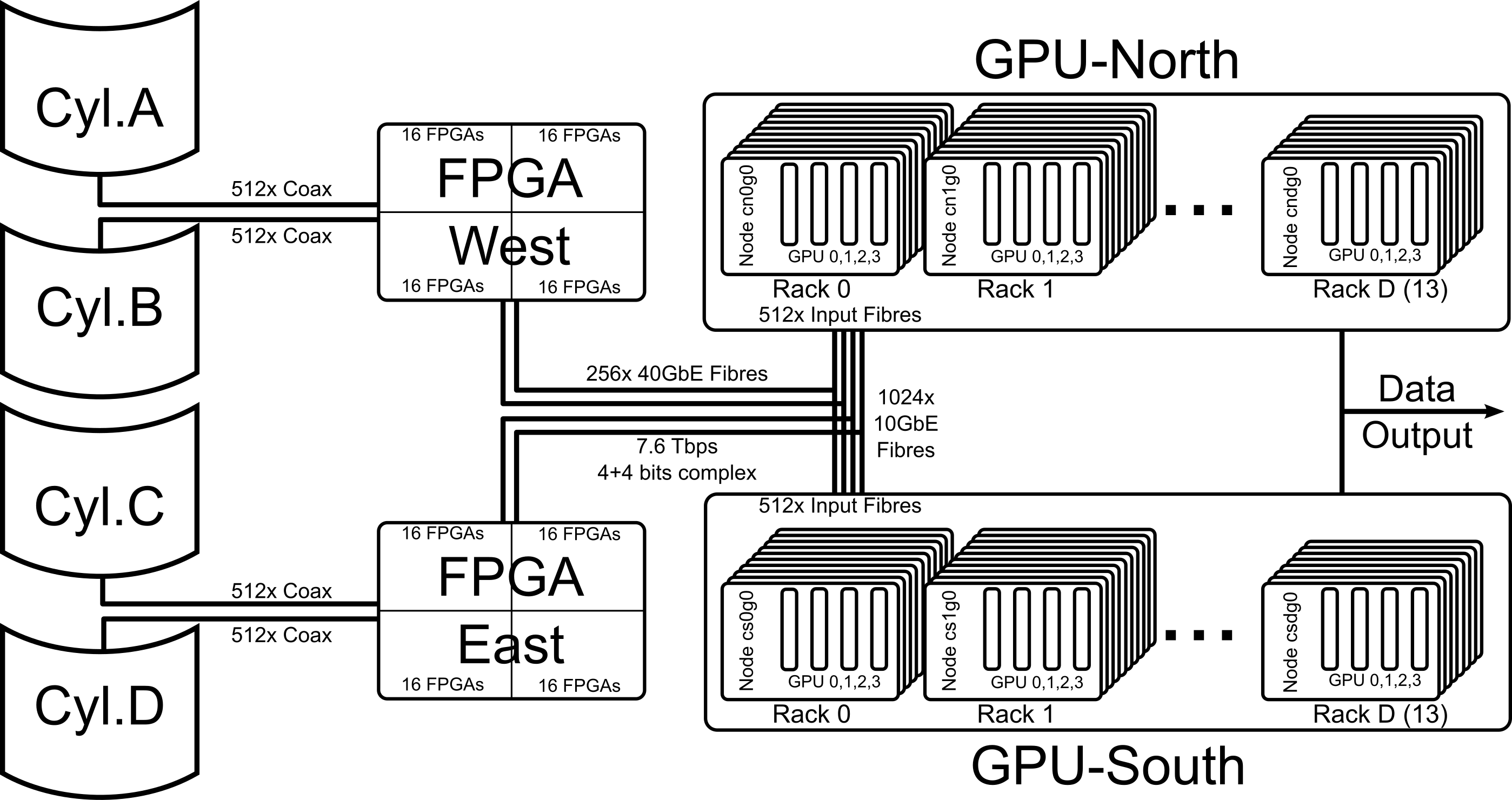
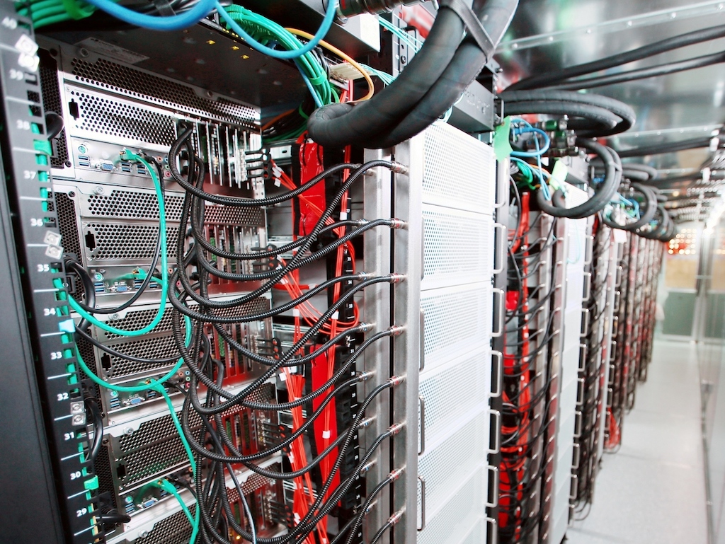
The overall structure of the CHIME signal processing system is shown in Figure 1, with key parameters collected in Table 2.1 and a photograph of the completed correlator in Figure 2; further description follows.
[ht] Number of Receiver-Polarizations 2048 Observing Band 400-800 MHz Collecting Area 8000 m2 Number of Frequency Channels 1024 Receiver Noise Temperature K Frequency Resolution 390 kHz North-South Field of View East-West Field of View - Selected observational parameters of the CHIME instrument.
CHIME’s light-gathering apparatus consists of four semi-parabolic dishes, each 100 m in length and 20 m in width with a 5 m focal length. The central 80 m of each cylinder is instrumented with 256 custom-designed dual-polarization clover-leaf receivers (Deng & Campbell-Wilson, 2014) spaced cm apart, for a total of 2048 distinct receiver-polarization ‘inputs’ to the correlator system.
The signal from each receiver-polarization is separately amplified and transported along coaxial cable to its cylinder’s adjacent F-engine enclosure. There, it is further filtered and amplified before being fed to an FPGA-based digitizer and Fourier-transform system (Bandura et al., 2016a). This system consists of 128 custom-built motherboards, which employ the Xilinx Kintex-7 420T FPGA111 https://www.xilinx.com/products/silicon-devices/fpga/kintex-7.html for signal processing. A single motherboard hosts two daughter boards, each of which provides the coaxial connectors for four receiver-polarizations of RF signal input. Each daughter board also houses two Teledyne EV8AQ160 Analog-to-Digital Converters222 https://www.teledyne-e2v.com/products/semiconductors/adc/ev8aq160 whose output is transferred to the motherboard as input to a Polyphase Filter Bank and Fast Fourier Transform.
At this point, each FPGA has data from only one receiver-polarization but over the instrument’s full 400-800 MHz frequency range; an FX architecture requires this data be regrouped (turned into sets of single-frequency-channel data from all receiver-polarizations) to permit the construction of full-array visibilities. This regrouping can be thought of as the transposition of a two-dimensional data array in receiver-frequency space, and is often referred to as a ‘corner turn’ in correlator-specific literature. The backplane within each ‘crate’ of 16 FPGAs and high-speed inter-crate connections lack the capacity to complete the transposition of the data, assembling the complete cylinders (but not the full array) in the final inter-crate transfer stage (see Bandura et al. (2016b) for details). The data is therefore transferred to the X-engine as ‘bundles’ of four frequency channels, each of which has data from only one cylinder. Four of these bundles are combined in each of the X-engine’s GPU nodes to provide the required full-array coverage for all four frequencies.
CHIME’s spatial processing takes place on 256 custom-built GPU nodes, each processing four frequency channels, which collectively perform the full outer-product correlation of 2048 inputs for each of the 1024 frequency channels every 2.56 microseconds. These nodes additionally form a set of 10 phased-array beams for pulsar timing (CHIME/Pulsar Collaboration et al., 2020; Ng, 2017) and perform up-channelization and Fourier-transform-based beam formation on an additional copy of the data prior to its export to the FRB back-end (Ng et al., 2017). Additional parallel processing streams are currently under development. The X-engine GPU nodes reside in a pair of purpose-built enclosures, and are supported by a multi-stage liquid-based cooling system; these are further described in §2.4.
Post-correlation, visibility data is averaged and recorded for later physical transport to Compute Canada facilities for processing and analysis. Beams formed for the Pulsar and FRB components of the system are exported over the site’s internal network for further processing.
2.2 Computational Requirements
For an FX-architected correlator, the cost of the inter-receiver product dominates the overall computational requirements of visibility formation. For an instrument with receiver-polarizations and instantaneous bandwidth of the naïve computational cost of the ‘X’ stage – including autocorrelations – is complex multiply-accumulate (cMAC) operations per second. CHIME therefore requires cMAC/s 0.8 PcMAC/s to complete this stage of its correlation. For comparison, the computational requirements (as measured by ) of other radio interferometers are shown in Table 2.2.
[ht] Instrument Reference (MHz) (TcMAC/s) CHIME† hic 2048 400 839 SKA LFAA Dewdney et al. (2015) 1024 300 157 HERA–350† DeBoer et al. (2017) 700 200 49 MWA Phase II† Wayth et al. (2018) 512 327 43 CHIME Pathfinder† Bandura et al. (2014) 256 400 13.6 MWA Phase I† Ord et al. (2015) 256 327 10.8 OVRO LEDA† Kocz et al. (2015) 512 58 7.6 MeerKAT Phase 1 Booth & Jonas (2012) 128 750 5.9 ALMA ACA Warmels et al. (2018) 64 2000 4.2 PAPER–128† Ali et al. (2015) 256 100 3.3 ngVLA (proposed)∗ Selina et al. (2018) 526 20000 2777 ALMA BLC∗ Warmels et al. (2018) 64 16000 33 EVLA WIDAR∗ Perley et al. (2009) 27 16000 6.0 The computational requirements of other radio X-engines, as measured by the metric . Several of these () are FX hybrid FPGA-GPU designs as described in §1. The ALMA BLC, EVLA WIDAR, and ngVLA correlators () use or plan to use ‘hybrid-XF’ or ‘FFX’ architectures, making direct comparisons difficult.
The CHIME X-engine was originally envisioned as a Fourier-transform-based system (Tegmark & Zaldarriaga, 2009, 2010) which exploited redundancies in baseline geometry to permit efficient spatial correlation. Interest in alternative correlation techniques as well as the requirements of the CHIME/Pulsar and CHIME/FRB experiments placed a premium on the ability to modify the X-engine software quickly and with minimal development effort. The goal of an adaptable, extensible, and re-configurable correlator system motivated the selection of GPUs as a both powerful and flexible processing substrate. This flexibility, along with the increasing computational power and efficiency of mass-market GPUs, allowed a variety of algorithmic improvements and optimizations which ultimately enabled a full-correlation X-engine which runs at a 100% duty cycle in parallel with a variety of beam-forming and spectral up-sampling tasks.
[ht] Number of Nodes 256 Number of Enclosures 2 Number of Racks 26 Nodes per Rack 8 or 10 CPUs per Node 1 GPUs per Node 2 dual-chip Total Main Memory 32 TiB Main Memory per Node 128 GiB Select parameters of the CHIME X-engine as a whole; see also Tables 3.1 and 3.2.
[ht] Parameter per Node per GPU Spectral Channels 4 1 Observing Bandwidth 1.56 MHz 390 kHz Required cMAC/s Select parameters of the CHIME X-engine nodes; see also Tables 3.1 and 3.2.
The total data transfer bandwidth required between the F- and X-stages is for data with a total bit depth of . In the case of CHIME, is 8 bits (4 bits each for the real and imaginary components), resulting in a minimum of Tb/s. Associated flags and metadata (644 B for each 4096 B of data) further increase this data volume, resulting in a total input bandwidth of Tb/s.333 As a comparison, Tb/s is 2490 PB/month; total global IP traffic in 2019 was estimated at 201,000 PB/month (Cisco, 2018). CHIME therefore requires F–X data transfer at a rate equal to of global Internet bandwidth.
2.3 The GPU Processing Nodes
Post-Fourier-transform, the data for each frequency channel may be processed independently; this was therefore selected as the axis across which to distribute the processing tasks. The fundamentals of the array dictate that correlating each kHz frequency channel requires Gb/s of input bandwidth and 819 GcMAC/s of effective processing power (as described in §2.2).
The number of frequency channels which could be processed on a given node was primarily determined by the availability of PCIe connections for data transfer. With the then-current Intel C612 chipset, the number of PCIe lanes available corresponded to each node hosting four GPUs, each of which processed a single frequency channel.
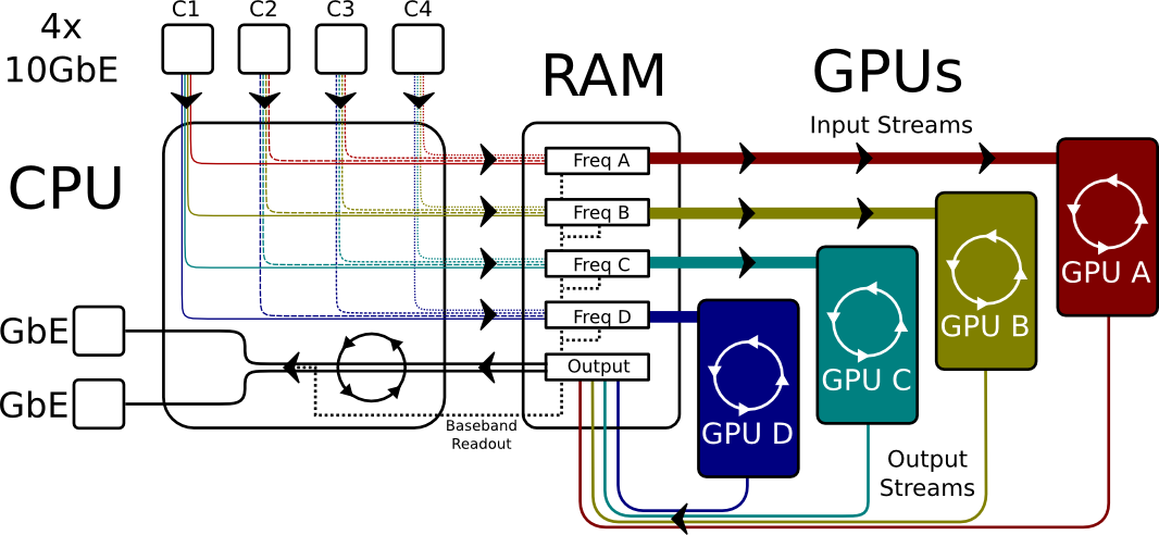
A schematic overview of the data flow within a GPU node is shown in Figure 3: each node gathers 4 10 GbE links from the F-engine, each containing a set of four (not necessarily adjacent) frequencies from one of the four cylinders. Its CPU completes the transpose, aligning the data according to its metadata timestamp and sending a complete frequency band to each of the four GPUs for processing. It then exports the integrated, processed data over a pair of GbE links. The hardware components which were selected for the nodes are listed in Table 4; an assembled node’s interior is shown in Figure 4. A description of each component, and the reasons for each particular choice, appear below.
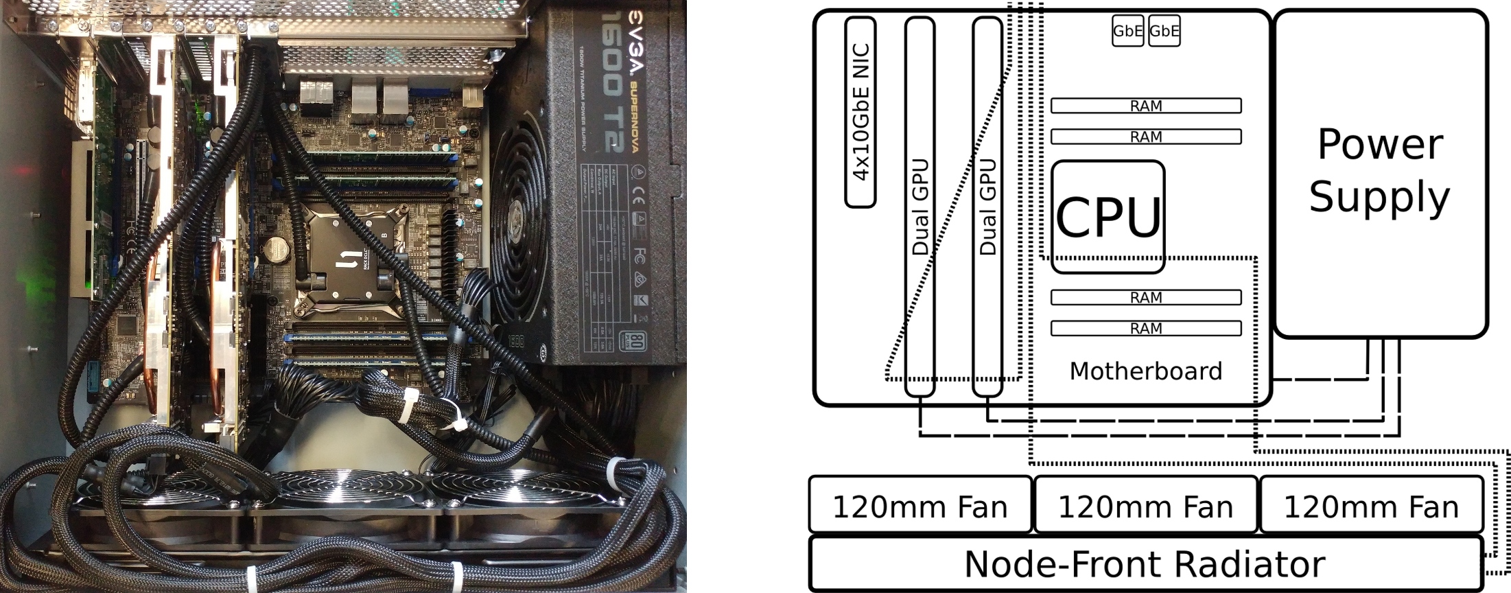
[ht] Component Hardware Selected GPUs 2 AMD FirePro S9300x2 CPU Intel Xeon E5-2620v3 NIC Silicom PE310G4i71L-XR Motherboard Supermicro X10SRA-F Memory 8 16GB DDR4 Power Supply EVGA SuperNOVA 1600 T2 Chassis General Technics CS893 Cooling CoolIT Custom-Built The hardware configuration of a CHIME X-engine processing node.
GPUs
The AMD FirePro S9300x2 supports two GPU processing chips per board, allowing a dense configuration and supplying the required processing power for correlation and auxiliary processing tasks. The specific requirements of the correlation algorithm led to the selection of the then-current AMD ‘Fiji’ GPU platform as it had the performance and instructions required. Our choice of GPU was greatly influenced by the availability of the ‘MAD24’ operation, which allowed us to effectively perform multiple simultaneous low-bit-depth arithmetic operations; these improved the correlation efficiency by a factor of two at the cost of additional bookkeeping, a substantial performance improvement for our use case (Klages et al., 2015).
CPU
Our processing and data transportation requirements (particularly PCIe lane requirements) limited the choice of CPU to the then-current Intel line-up. The selected Intel Xeon E5-2620v3 supports 40 lanes of PCIe3 traffic (required for our data transfer) and has 6 cores operating at 2.4 GHz, sufficient for all the processing and data manipulation we require. Its power consumption is extremely low (85 W TDP), and it is substantially less expensive than its consumer-oriented i7 counterpart.
Network Interface
We required a network interface card (NIC) to provide 4 10 GbE inputs with Enhanced Small Form Factor Pluggable (SFP+) physical connectors. The Silicom PE310G4i71L-XR, a quad-10 GbE NIC built around Intel XL710 chipset, supports the DPDK444https://dpdk.org kernel bypass libraries which we employ in our networking code.
Motherboard
The primary requirement for the motherboard was the number of available PCIe connectors, arranged so that two dual-slot GPUs and a network card could be operated simultaneously. Additional considerations included the memory and CPU options supported and the presence of dual GbE ports. The Supermicro X10SRA-F met or exceeded all our criteria and additionally supports the Internet Protocol Management Interface (IPMI), allowing for remote management at a sub-OS level.
Memory
The primary system memory is a set of registered and ECC-enabled Kingston KVR24R17D4/16 DDR4 DIMMs. We originally allocated the required 64 GiB of memory as 4 16 GiB modules rather than 8 8 GiB – this made very little difference to the net cost but allowed for a trivial upgrade to 128 GiB per node (8 16 GiB), completed in November of 2018. The additional memory allows the X-engine to buffer substantially more baseband data (seconds in total) for replay in the event of an FRB detection (CHIME/FRB Collaboration et al., 2018).
Power Supply
The EVGA SuperNOVA 1600 T2 is a high-capacity ATX-form-factor power supply, with modular cabling and sufficient power connections to supply the GPUs with the 2 8-pin PCI power connections they each require. In order to reduce both power consumption and waste heat generated, the node power supplies have substantial excess capacity. A 1600W 80plus Titanium power supply is rated at efficiency when loaded at 1kW with 208V power; the reduction in electrical consumption significantly outweighs the additional cost given the system’s near-continuous operation.
Chassis
Custom-designed for CHIME, the General Technics CS893 supports a 3 120 mm node-front radiator and 8 PCIe devices in a maximally-compact footprint. The main body of the chassis has a depth of only 38 cm, with a standard 4U rack-mount profile of 42.6 17.5 cm. The use of a standard ATX motherboard and power supply, full-height PCIe cards, and 120 mm cooling fans dictated a minimum 4U height for the chassis. Most commercially-available 4U chassis devoted significant space to storage devices; the GPU nodes were designed to run without persistent storage, and so could be much more compact.
Cooling
The GPU and CPU dies are cooled by custom-designed CoolIT direct-contact liquid cooling blocks, exhausting heat to the in-rack coolant loops. Each node has two independent coolant loops, one of which connects to the two dual-chip GPUs while the other serves the CPU and radiator. The node-front radiator supports 3 120 mm fans and couples air to the heat transfer fluid, regulating the air temperature inside the enclosure.
2.4 Supporting Infrastructure
Infrastructure requirements followed directly from the nodes’ density and composition. Covering the 1024 frequency channels requires 256 nodes, divided into racks of 8 or 10 nodes which operate as independent power and cooling entities. These are housed in two enclosures, each with 128 nodes in 13 racks as well as two racks for additional networking and monitoring equipment.
2.4.1 Racks and Enclosures
The outermost enclosures are a pair of ISO 668 1AA-size (‘40-foot’) intermodal shipping containers. Each houses a commercially-purchased Raymond EMC Faraday cage which provides dB of RFI shielding from sub-MHz to many-GHz frequencies. One end of the ‘RFI cage’ houses both the low-pass filters through which electrical power enters the RFI cage and the half-meter-square brass bulkhead through which data lines are routed. In order to prevent RF leakage, the fibre-optic data lines enter and exit the Faraday cage through a bulkhead inset with cylindrical waveguides with an inner diameter of 1” and a length of 12”; these attenuate radiation at frequencies below GHz by 190-380 dB (Brewer, 2001). The opposite wall of the RFI cage is fitted with a human-sized door and a honeycomb-mesh ventilation window; it further includes a half-meter-square brass bulkhead which permits the primary coolant lines to enter and exit the RFI cage.
Within each RFI cage, the nodes are further grouped into racks. The Tripp Lite SR4POST open-frame 45U four-post racks are extremely shallow (56 cm), as permitted by the custom diskless chassis. The nodes are mounted on General Technics RK500 slide rails whose modest length allows nodes to be removed easily in the restricted rack-front space. The racks are arranged along the centre of each enclosure, facing in alternating directions in order to avoid a large-scale air pressure gradient.
2.4.2 Power Distribution
The power consumed by the contents of each correlator enclosure is provided in the form of 5 separate 208 V-3 power cables, which are distributed to a set of 15 outlets along the length of the enclosure. Each rack has a vertical-mount Power Distribution Unit (PDU) which breaks the main supply out into a number of 208 V single-phase outlets suitable for powering the nodes and associated equipment. The Raritan PX3-5547 PDU selected enables network-controlled monitoring and switching of outlets, per-outlet current limiting and alarms, and control & logging via SSH.
2.4.3 Cooling System
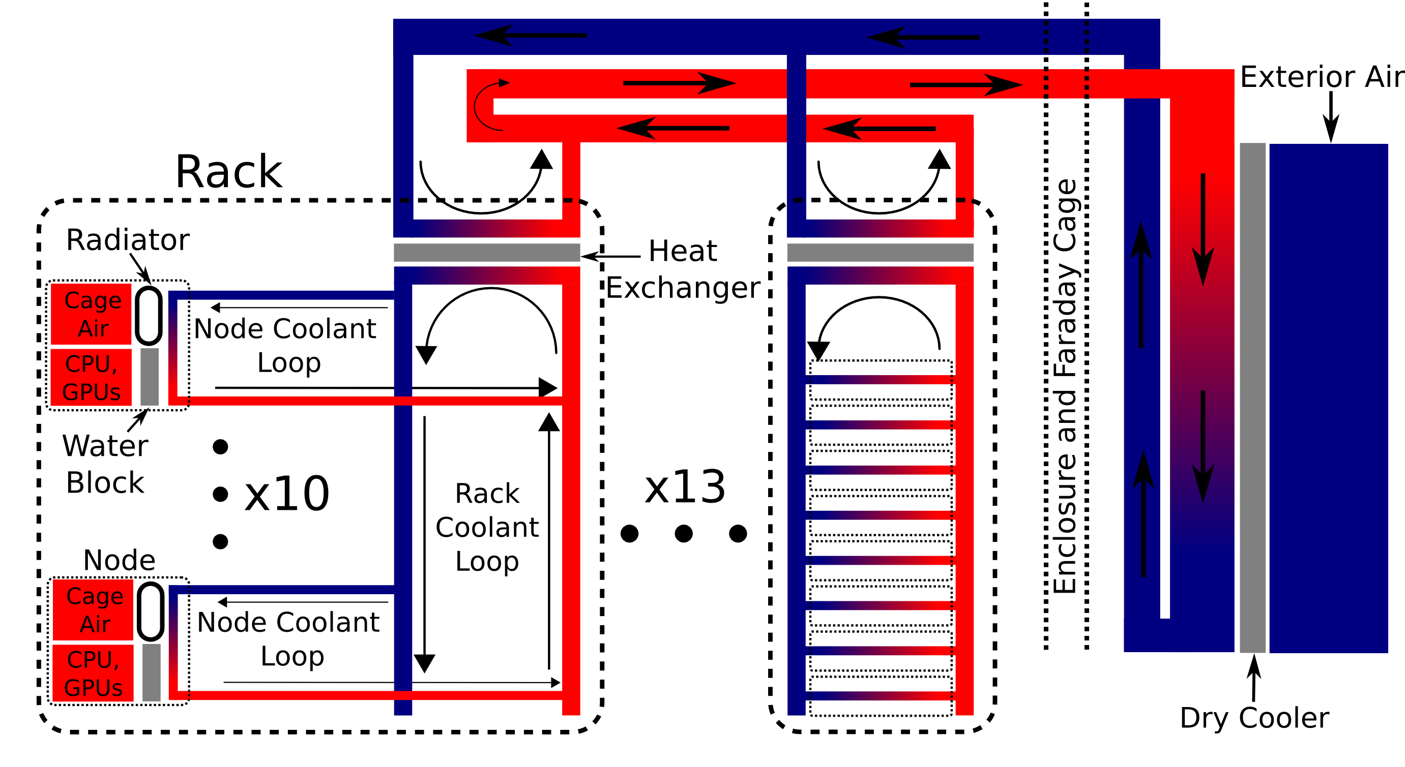
Refrigerated-air cooling options, the traditional datacentre heat transfer solution, require significant electrical power and would necessitate moving large volumes of air through the enclosure’s heavy RFI shielding. The CHIME X-engine cooling system uses a liquid heat-transfer medium to couple the heat sources inside the enclosure to the exterior air through a large ‘dry cooler’ (a Direct Coil FC07AV5D178). A schematic of this system is shown in Figure 5; see §3.3 for details of the system’s performance.
Each rack runs an independent sealed-loop system, which is coupled to the primary coolant through a heat exchanger. The rack-top liquid handler (a CoolIT CHx40) combines a heat exchanger, reservoir, & pump and provides basic remote monitoring and control capabilities. The secondary coolant is distributed through a custom-engineered manifold, and provides direct-contact liquid cooling to the CPU and GPUs as well as flowing through a node-front radiator to remove heat from the air circulating in the enclosure.
2.4.4 Network and Management
The input data lines connecting the F-engine and X-engine are 256 fibre-optic ‘hydra’ cables which convert the single Quad SFP+ (QSFP) connection at the F-Engine’s FPGAs to 4 SFP+ connectors for the GPU nodes. Each cable is divided between four nodes (either within one rack or between two adjacent racks) so that each GPU node receives a matched set of four frequencies from each cylinder.
The output data network is a simple hierarchical model, with first-stage switches aggregating the GbE links from the nodes and sending 10 GbE links to a large central switch. Each of the Cisco Catalyst 3650 (WS-C3650-48TQ-L) first-layer switches has 48 GbE RJ45 and 4 10 GbE SFP+ ports; this is sufficient to handle the 40 links from two racks’ worth of nodes, as well as individual connections to the PDUs, liquid-handler units, and file servers. The central switch, a Cisco Nexus 3132Q (N3K-C3132Q-40GX), collects the 10 GbE links from the first-stage switches and forwards the data to dedicated servers for final accumulation and storage.
The GPU processing nodes have no persistent storage, instead booting and mounting filesystems from a set of Dell PowerEdge r410 file servers. This simplifies software maintenance and updates, provides a moderate level of redundancy, and minimizes configuration overhead. These same file servers also record logs and performance of individual nodes, and provide a virtual private network (VPN) for remote access.
Much of the monitoring data is supplied by sensors built into the GPU nodes (CPU and GPU temperatures) and PDUs (power draw), with additional data coming from the CHx40 units (coolant temperatures and flow rate, ambient air temperature and humidity). Enclosure-wide environmental monitoring is enabled by an NTI ENVIROMUX-5D unit which currently connects to door-state and leak-detection sensors.
System monitoring data collection is based on the Prometheus555https://prometheus.io/ monitoring system, which collects data at set intervals and maintains a database of the time-series for each metric. Grafana666https://grafana.com/, a commercially-developed monitoring and data-presentation system, is used to convert the raw sensor data in a set of ‘dashboards’ summarizing the system’s status. The Prometheus system has also been configured to send automated alerts to the CHIME collaboration’s internal Slack777https://slack.com messaging system if certain criteria are met. Sensor values indicating severe problems (critical overheating or coolant leaks) automatically halt the correlator’s operation, either by stopping the main correlation software or by directly cutting power to the affected area via the PDUs’ network interfaces. The CPUs’ temperature-driven Catastrophic Shutdown Detectors (Intel 2018) and the PDU and PDC circuit breakers remain the automated fail-safe mechanisms of last resort.
3 CHIME Correlator Systems Operation and Performance
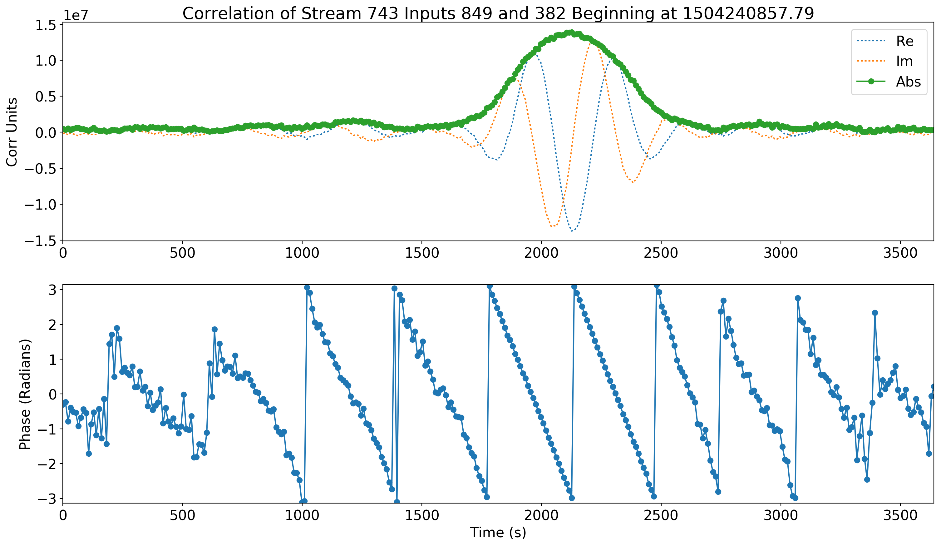
The most fundamental test of any correlator system is if it permits the telescope to observe the sky; the CHIME correlator emphatically succeeds at this. An initial on-sky observation of Cygnus A was taken on 31 August 2017. The correlation was computed for the complete set of 2048 inputs at a subset of frequencies; the post-outer-product data was recorded to disk in a raw, packetized state and then transported off-site for processing and visualization. Figure 6 shows a single-baseline, single-frequency timestream covering the entire approximately-one-hour observation. The instrument’s main beam profile and a linear phase evolution near transit may be readily observed; this supported early tests that the system was observing and correctly interpreting an actual astronomical signal.
In addition to initial cosmological observations, the CHIME X-engine’s successful operation has enabled a wealth of discoveries by the CHIME/FRB collaboration (CHIME/FRB Collaboration et al., 2019a, b, 2020b, 2020a); these further validate the end-to-end functionality of the correlator system. A paper providing a broader overview of CHIME and its operations (CHIME Scientific Collaboration et al., 2020) is forthcoming.
3.1 Data Transfer and Processing Performance
CHIME’s high-efficiency real-time data processing software, kotekan (Renard et al., 2020), was written in OpenCL and with AMD’s Heterogeneous System Architecture (HSA), enabled by HSA compilers which translated C++ code into the AMD Graphics Core Next Instruction Set Architecture (GCN ISA). The correlation task described in §1 is comfortably within the available resources, even permitting the GPUs’ operation at a reduced clock rate (722 MHz, compared to their 975 MHz base clock) and reduced voltages (variable per-GPU), which combine to vastly reduce power consumption. Table 3.1 details the extent to which specific tasks contribute to the GPU’s overall occupancy.
[ht] Task Task Length (ms) Occupancy (%) Re-Order and Pre-Sum 1.0 0.8 RFI Excision 1.1 0.9 Correlation 93.4 74.3 High-Spectral-Resolution Tap 0.2 0.2 Pulsar Beamforming 5.9 4.7 FRB Processing 20.9 16.6 Total 122.6 97.4 The approximate length of time required to complete each processing task on the GPU, and the corresponding percentage of the GPU processing duty cycle it occupies. The tasks are measured per ‘block’ of 49152 samples, ms in length. The values presented are at a clock speed of 722 MHz; this reduction from the base clock of 975 MHz increases the GPUs’ occupancy but consumes significantly less electrical power and generates correspondingly less waste heat. Additional details of the GPU nodes’ software and data processing may be found in Renard et al. (2020).
Table 3.1 provides typical data transfer rates into and out of the GPU nodes. The networking software employs DPDK, a kernel bypass network subsystem, to handle the extremely high rate of incoming data. Tests show that receiving the data from the FPGAs, completing the transpose, and dispatching it to the GPUs is well within the capacity of the selected CPU; it occupies two of the CPU’s six physical cores. Post-correlation data may be exported at a range of cadences, but the substantial time-integration involved ensures that the output is well within the capacity of the two onboard GbE links.
[ht] Data Transfer Rates Per Node (Gb/s) Total (Gb/s) In Fourier-Transformed Voltage Samples 25.6 6553 Flags and Metadata 4.0 1030 Total 29.6 7583 Out Correlated Visibilities (at 10 s integration) 0.05 13.6 FRB Beams 0.59 153 Pulsar Beams 0.25 64 Flags and Metadata 0.03 8.5 Total 0.92 239 Typical data rates into and out of the CHIME GPU nodes. Input data for each node is carried on GbE, while output data leaves on GbE connections. Additional details of the GPU nodes’ software and data processing may be found in Renard et al. (2020).
3.2 Power Consumption
Using commissioning-epoch code and the AMD ROCm 1.9.211 driver the power consumption of a typical GPU node when performing both the full correlation and typical auxiliary processing is W, significantly below the 1000 W design ceiling. Table 3.2 details the power consumption of the GPU correlator system, based on PDU monitoring data recorded during commissioning tests. The X-engine’s total power consumption (with GPUs operating at a reduced clock of 722 MHz) is kW, a significant reduction from the design maximum of 256 kW with an accompanying reduction in operating costs. Under typical conditions, of the system’s total power is used for cooling, which compares favorably to the of the most efficient industrial systems available888 The latter value is the theoretical minimum for a system with an Energy Efficiency Ratio of 15; standard datacentre planning guides (Limoncelli et al., 2007; Sawyer, 2004) suggest as a typical value..
[ht] Power Consumption Per Node (W) Total (kW) GPU Nodes: GPUs 4140 CPU 70 Misc. Total 700 180 Infrastructure 4.3 Primary Coolant Pump 5.0 Dry Cooler Fans 28.0 Total 220 Total power consumption for the GPU correlator system with all 256 nodes operating simultaneously. The ‘infrastructure’ entry includes file servers, liquid-handler units, and network equipment.
3.3 Cooling System Performance
At each stage of the heat transfer system described in §2.4.3 and Fig. 5, the thermal resistance produces a temperature gap across the heat exchanger. In steady-state operation the temperature of the directly-liquid-cooled components will therefore float a fixed amount above the input coolant temperature. Similarly, the air inside the RFI cages (and supplied to the air-cooled components) will vary with the supplied coolant’s temperature.
Tests during commissioning permitted the evaluation of these differentials; Table 3.3 provides values extracted from a full month of temperature data. These indicate that under representative loads the GPUs are ∘C warmer than the external ambient temperature and that the internal air temperature floats ∘C above the same. The former values are still far cooler than a typical air-cooled GPU or CPU, and so are not a source of concern. The enclosure air temperature does, however, provide one edge of the operating envelope, as it is the only source of cooling for a number of components.
[ht] Thermal Interface Location (∘C) Cumulative (∘C) External Air - Primary Coolant Dry Cooler — Primary Coolant - Secondary Coolant CHx40 — Secondary Coolant - Internal Air Radiator 2.6 2.2 14.3 2.9 Secondary Coolant - CPU CPU Loop 6.1 2.5 17.8 3.1 Secondary Coolant - GPU 0 GPU Loop 8.7 2.3 20.4 3.0 Secondary Coolant - GPU 1 GPU Loop 12.2 2.7 23.9 3.3 Secondary Coolant - GPU 2 GPU Loop 16.1 3.4 27.8 3.9 Secondary Coolant - GPU 3 GPU Loop 19.2 4.0 30.9 4.4 Representative temperature differentials at various stages of the heat transfer system, based on commissioning tests from February 2018. As the external air temperature was ∘C during this period, the dry cooler was run well below full capacity; the maximum value listed is from the manufacturer’s specifications. The CHx40 liquid-handler units’ was found to vary linearly with the racks’ power consumption; the value in the table corresponds to the nominal 7 kW per rack. The sequentially increasing temperature of the GPUs is due to their serial coolant flow.
The external-internal air temperature differential is higher than expected; the manufacturer’s specifications for the CHx40 liquid-handler units were derived from flawed simulations which predicted a thermal gap of C/kW rather than the measured C/kW. This presents an obstacle to mid-day operation during the hottest weeks of the year, as the internal air temperature would be high enough to damage more thermally-sensitive server and switch components; the system will be required to cease operation during these periods. The cooling system is otherwise able to exhaust the entire system’s waste heat and maintain appropriate internal temperatures with minimal power consumption.
4 Conclusion
The CHIME correlator X-engine is capable of correlating the instrument’s 2048 receiver-polarizations over a full 400 MHz of bandwidth. This requires 0.8 PcMAC/s of computation on Tb/s of input from the F-engine, which is accomplished by the system’s 256 nodes using commercially-available GPUs as computationally powerful, cost-effective units for large-scale integer matrix products. The system consumes a modest 220 kW of electrical power, including that used to run the fresh-air liquid-cooling system which keeps the GPUs at temperatures far below those of typical air-cooled solutions.
The success of the CHIME correlator X-engine may be illustrated by the results it has enabled; although the primary cosmological mission is ongoing (Bandura et al., 2014; CHIME Scientific Collaboration et al., 2020), the CHIME/FRB component has made epochal contributions to FRB observations. These include the first FRBs seen in its frequency range (CHIME/FRB Collaboration et al., 2019b), the second-known repeating FRB (CHIME/FRB Collaboration et al., 2019a), the first known periodic FRB (CHIME/FRB Collaboration et al., 2020b), and the localization of an FRB to a magnetar within our own galaxy (CHIME/FRB Collaboration et al., 2020a).
The CHIME correlator X-Engine achieves its design requirements with high efficiency, modest initial cost, and low power consumption (for a system of this size). It takes full advantage of the highly-efficient integer computation available on modern GPUs; commercial PCIe network cards provide a reliable and cost-effective interface capable of handling the immense intra-correlator bandwidth required, while mass-market network switches capable of handling full-rate transfer of GbE and 10 GbE over standard Ethernet make the output data handling quite straightforward. Additional details of the system hardware, layout, and performance are available in Denman (2019).
The system’s attributes are largely dictated by the specifications of the CHIME instrument; the number of receivers, bandwidth, bit depth, and F-engine structure all have non-trivial implications for the overall design. Although derived implementations will therefore require careful planning and design modifications, similar GPU-based X-Engines may provide powerful, inexpensive, and computationally efficient correlation for future radio interferometers.
4.1 Future Development
The CHIME spatial processing system could only make use of the technologies available at the time of its development; future correlators may realize extensive improvements by incorporating more-recently-developed technologies. Extensions of the CHIME correlator to support additional capabilities and receivers are under examination, and lessons learned during CHIME development will be applied to future correlator systems. Additionally, continued optimization of the GPU kernels is on course to enable further reduction of the GPU core clocks, and therefore significant reductions in power consumption.
The continuing adoption of PCIe v4.0 by hardware manufacturers and the increasing number of PCIe lane supported on mass-market CPUs loosens the NIC-GPU data transfer bottleneck; particularly for arrays with relatively larger bandwidth but fewer receivers, this may substantially improve the efficiency of a GPU-based X-engine design.
The introduction of ‘tensor cores’, GPU components optimized for low-bit-depth integer matrix multiplication and accumulation, offers a potential order-of-magnitude acceleration for correlation, and is the subject of active research and development (NVIDIA Corporation, 2019; Romein & Veenboer, 2019).
GPU-based correlation, particularly with the advent of tensor cores and improved data-transfer technologies, offers great potential for high-efficiency, low-cost digital signal processing. The offers an unprecedented opportunity for large-scale radio interferometers with significantly reduced cost and improved performance.
Acknowledgements
The authors would like to acknowledge development contributions from Advanced Micro Devices (AMD) and CoolIT Systems.
References
- Ali et al. (2015) Ali, Z. S., Parsons, A. R., Zheng, H., Pober, J. C., Liu, A., Aguirre, J. E., Bradley, R. F., Bernardi, G., Carilli, C. L., Cheng, C., DeBoer, D. R., Dexter, M. R., Grobbelaar, J., Horrell, J., Jacobs, D. C., Klima, P., MacMahon, D. H. E., Maree, M., Moore, D. F., Razavi, N., Stefan, I. I., Walbrugh, W. P. & Walker, A. [2015] ApJ 809, 61, 10.1088/0004-637X/809/1/61.
- Bandura et al. (2014) Bandura, K., Addison, G. E., Amiri, M., Bond, J. R., Campbell-Wilson, D., Connor, L., Cliche, J.-F., Davis, G., Deng, M., Denman, N., Dobbs, M., Fandino, M., Gibbs, K., Gilbert, A., Halpern, M., Hanna, D., Hincks, A. D., Hinshaw, G., Höfer, C., Klages, P., Landecker, T. L., Masui, K., Mena Parra, J., Newburgh, L. B., Pen, U.-l., Peterson, J. B., Recnik, A., Shaw, J. R., Sigurdson, K., Sitwell, M., Smecher, G., Smegal, R., Vanderlinde, K. & Wiebe, D. [2014] “Canadian Hydrogen Intensity Mapping Experiment (CHIME) pathfinder,” Ground-based and Airborne Telescopes V, p. 914522, 10.1117/12.2054950.
- Bandura et al. (2016a) Bandura, K., Bender, A. N., Cliche, J. F., de Haan, T., Dobbs, M. A., Gilbert, A. J., Griffin, S., Hsyu, G., Ittah, D., Parra, J. M., Montgomery, J., Pinsonneault-Marotte, T., Siegel, S., Smecher, G., Tang, Q. Y., Vanderlinde, K. & Whitehorn, N. [2016a] Journal of Astronomical Instrumentation 5, 1641005, 10.1142/S2251171716410051.
- Bandura et al. (2016b) Bandura, K., Cliche, J. F., Dobbs, M. A., Gilbert, A. J., Ittah, D., Mena Parra, J. & Smecher, G. [2016b] Journal of Astronomical Instrumentation 5, 1641004, 10.1142/S225117171641004X.
- Booth & Jonas (2012) Booth, R. S. & Jonas, J. L. [2012] African Skies 16, 101.
- Brewer (2001) Brewer, R. [2001] Evaluation Engineering 2001-01.
- CHIME Scientific Collaboration et al. (2020) CHIME Scientific Collaboration et al. [2020] “in prep.” In prep.
- CHIME/FRB Collaboration et al. (2020a) CHIME/FRB Collaboration, :, Andersen, B. C., Band ura, K. M., Bhardwaj, M., Bij, A., Boyce, M. M., Boyle, P. J., Brar, C., Cassanelli, T., Chawla, P., Chen, T., Cliche, J. F., Cook, A., Cubranic, D., Curtin, A. P., Denman, N. T., Dobbs, M., Dong, F. Q., Fandino, M., Fonseca, E., Gaensler, B. M., Giri, U., Good, D. C., Halpern, M., Hill, A. S., Hinshaw, G. F., Höfer, C., Josephy, A., Kania, J. W., Kaspi, V. M., Landecker, T. L., Leung, C., Li, D. Z., Lin, H. H., Masui, K. W., Mckinven, R., Mena-Parra, J., Merryfield, M., Meyers, B. W., Michilli, D., Milutinovic, N., Mirhosseini, A., Münchmeyer, M., Naidu, A., Newburgh, L. B., Ng, C., Patel, C., Pen, U. L., Pinsonneault-Marotte, T., Pleunis, Z., Quine, B. M., Rafiei-Ravandi, M., Rahman, M., Ransom, S. M., Renard, A., Sanghavi, P., Scholz, P., Shaw, J. R., Shin, K., Siegel, S. R., Singh, S., Smegal, R. J., Smith, K. M., Stairs, I. H., Tan, C. M., Tendulkar, S. P., Tretyakov, I., Vanderlinde, K., Wang, H., Wulf, D. & Zwaniga, A. V. [2020a] arXiv e-prints , arXiv:2005.10324.
- CHIME/FRB Collaboration et al. (2020b) CHIME/FRB Collaboration, Amiri, M., Andersen, B. C., Band ura, K. M., Bhardwaj, M., Boyle, P. J., Brar, C., Chawla, P., Chen, T., Cliche, J. F., Cubranic, D., Deng, M., Denman, N. T., Dobbs, M., Dong, F. Q., Fand ino, M., Fonseca, E., Gaensler, B. M., Giri, U., Good, D. C., Halpern, M., Hessels, J. W. T., Hill, A. S., Höfer, C., Josephy, A., Kania, J. W., Karuppusamy, R., Kaspi, V. M., Keimpema, A., Kirsten, F., Landecker, T. L., Lang, D. A., Leung, C., Li, D. Z., Lin, H. H., Marcote, B., Masui, K. W., McKinven, R., Mena-Parra, J., Merryfield, M., Michilli, D., Milutinovic, N., Mirhosseini, A., Naidu, A., Newburgh, L. B., Ng, C., Nimmo, K., Paragi, Z., Patel, C., Pen, U. L., Pinsonneault-Marotte, T., Pleunis, Z., Rafiei-Ravandi, M., Rahman, M., Ransom, S. M., Renard, A., Sanghavi, P., Scholz, P., Shaw, J. R., Shin, K., Siegel, S. R., Singh, S., Smegal, R. J., Smith, K. M., Stairs, I. H., Tendulkar, S. P., Tretyakov, I., Vanderlinde, K., Wang, H., Wang, X., Wulf, D., Yadav, P. & Zwaniga, A. V. [2020b] Nature 582, 351, 10.1038/s41586-020-2398-2.
- CHIME/FRB Collaboration et al. (2018) CHIME/FRB Collaboration, Amiri, M., Bandura, K., Berger, P., Bhardwaj, M., Boyce, M. M., Boyle, P. J., Brar, C., Burhanpurkar, M., Chawla, P., Chowdhury, J., Cliche, J.-F., Cranmer, M. D., Cubranic, D., Deng, M., Denman, N., Dobbs, M., Fandino, M., Fonseca, E., Gaensler, B. M., Giri, U., Gilbert, A. J., Good, D. C., Guliani, S., Halpern, M., Hinshaw, G., Höfer, C., Josephy, A., Kaspi, V. M., Landecker, T. L., Lang, D., Liao, H., Masui, K. W., Mena-Parra, J., Naidu, A., Newburgh, L. B., Ng, C., Patel, C., Pen, U.-L., Pinsonneault-Marotte, T., Pleunis, Z., Rafiei Ravandi, M., Ransom, S. M., Renard, A., Scholz, P., Sigurdson, K., Siegel, S. R., Smith, K. M., Stairs, I. H., Tendulkar, S. P., Vanderlinde, K. & Wiebe, D. V. [2018] ApJ 863, 48, 10.3847/1538-4357/aad188.
- CHIME/FRB Collaboration et al. (2019a) CHIME/FRB Collaboration, Amiri, M., Bandura, K., Bhardwaj, M., Boubel, P., Boyce, M. M., Boyle, P. J., Brar, C., Burhanpurkar, M., Cassanelli, T., Chawla, P., Cliche, J. F., Cubranic, D., Deng, M., Denman, N., Dobbs, M., Fandino, M., Fonseca, E., Gaensler, B. M., Gilbert, A. J., Gill, A., Giri, U., Good, D. C., Halpern, M., Hanna, D. S., Hill, A. S., Hinshaw, G., Höfer, C., Josephy, A., Kaspi, V. M., Landecker, T. L., Lang, D. A., Lin, H.-H., Masui, K. W., Mckinven, R., Mena-Parra, J., Merryfield, M., Michilli, D., Milutinovic, N., Moatti, C., Naidu, A., Newburgh, L. B., Ng, C., Patel, C., Pen, U., Pinsonneault-Marotte, T., Pleunis, Z., Rafiei-Ravandi, M., Rahman, M., Ransom, S. M., Renard, A., Scholz, P., Shaw, J. R., Siegel, S. R., Smith, K. M., Stairs, I. H., Tendulkar, S. P., Tretyakov, I., Vanderlinde, K., Yadav, P. & Collaboration, T. C. [2019a] Nature 566, 235, 10.1038/s41586-018-0864-x, URL https://doi.org/10.1038/s41586-018-0864-x.
- CHIME/FRB Collaboration et al. (2019b) CHIME/FRB Collaboration, Amiri, M., Bandura, K., Bhardwaj, M., Boubel, P., Boyce, M. M., Boyle, P. J., Brar, C., Burhanpurkar, M., Chawla, P., Cliche, J. F., Cubranic, D., Deng, M., Denman, N., Dobbs, M., Fandino, M., Fonseca, E., Gaensler, B. M., Gilbert, A. J., Giri, U., Good, D. C., Halpern, M., Hanna, D., Hill, A. S., Hinshaw, G., Höfer, C., Josephy, A., Kaspi, V. M., Landecker, T. L., Lang, D. A., Masui, K. W., Mckinven, R., Mena-Parra, J., Merryfield, M., Milutinovic, N., Moatti, C., Naidu, A., Newburgh, L. B., Ng, C., Patel, C., Pen, U., Pinsonneault-Marotte, T., Pleunis, Z., Rafiei-Ravandi, M., Ransom, S. M., Renard, A., Scholz, P., Shaw, J. R., Siegel, S. R., Smith, K. M., Stairs, I. H., Tendulkar, S. P., Tretyakov, I., Vanderlinde, K., Yadav, P. & Collaboration, T. C. [2019b] Nature 566, 230, 10.1038/s41586-018-0867-7, URL https://doi.org/10.1038/s41586-018-0867-7.
- CHIME/Pulsar Collaboration et al. (2020) CHIME/Pulsar Collaboration et al. [2020] “in prep.” In prep.
- Cisco (2018) Cisco [2018] “Cisco visual networking index: Forecast and trends, 2017-2022,” Tech. Rep. C11-741490-00, Cisco Systems Inc.
- Clark et al. (2011) Clark, M. A., La Plante, P. C. & Greenhill, L. J. [2011] arXiv e-prints , arXiv:1107.4264.
- DeBoer et al. (2017) DeBoer, D. R., Parsons, A. R., Aguirre, J. E., Alexander, P., Ali, Z. S., Beardsley, A. P., Bernardi, G., Bowman, J. D., Bradley, R. F., Carilli, C. L., Cheng, C., de Lera Acedo, E., Dillon, J. S., Ewall-Wice, A., Fadana, G., Fagnoni, N., Fritz, R., Furlanetto, S. R., Glendenning, B., Greig, B., Grobbelaar, J., Hazelton, B. J., Hewitt, J. N., Hickish, J., Jacobs, D. C., Julius, A., Kariseb, M., Kohn, S. A., Lekalake, T., Liu, A., Loots, A., MacMahon, D., Malan, L., Malgas, C., Maree, M., Martinot, Z., Mathison, N., Matsetela, E., Mesinger, A., Morales, M. F., Neben, A. R., Patra, N., Pieterse, S., Pober, J. C., Razavi-Ghods, N., Ringuette, J., Robnett, J., Rosie, K., Sell, R., Smith, C., Syce, A., Tegmark, M., Thyagarajan, N., Williams, P. K. G. & Zheng, H. [2017] PASP 129, 045001, 10.1088/1538-3873/129/974/045001.
- Deng & Campbell-Wilson (2014) Deng, M. & Campbell-Wilson, D. [2014] “The cloverleaf antenna: A compact wide-bandwidth dual-polarization feed for chime,” 2014 16th International Symposium on Antenna Technology and Applied Electromagnetics (ANTEM), p. 1, 10.1109/ANTEM.2014.6887670.
- Denman (2019) Denman, N. T. [2019] “Digital Signal Processing for the Canadian Hydrogen Intensity Mapping Experiment,” PhD thesis, University of Toronto.
- Dewdney et al. (2015) Dewdney, P., Turner, W., Braun, R., Santander-Vela, J., Waterson, M. & Tan, G. H. [2015] “Ska1 system baseline v2 description,” Tech. Rep. SKA-TEL-SKO-0000308, SKA Organization.
- Intel Corporation (2018) Intel Corporation [2018] Intel 64 and IA-32 Architectures Software Developer’s Manual, Intel Corporation.
- Klages et al. (2015) Klages, P., Bandura, K., Denman, N., Recnik, A., Sievers, J. & Vanderlinde, K. [2015] “GPU Kernels for High-Speed 4-Bit Astrophysical Data Processing,” Proceedings of the IEEE 26th International Conference on Application-specific Systems, Architectures and Processors, p. 164.
- Kocz et al. (2015) Kocz, J., Greenhill, L. J., Barsdell, B. R., Price, D., Bernardi, G., Bourke, S., Clark, M. A., Craig, J., Dexter, M., Dowell, J., Eftekhari, T., Ellingson, S., Hallinan, G., Hartman, J., Jameson, A., MacMahon, D., Taylor, G., Schinzel, F. & Werthimer, D. [2015] Journal of Astronomical Instrumentation 4, 1550003, 10.1142/S2251171715500038.
- Limoncelli et al. (2007) Limoncelli, T. A., Hogan, C. J. & Chalup, S. R. [2007] The Practice of System and Network Administration (Addison-Wesley Professional).
- Loeb & Wyithe (2008) Loeb, A. & Wyithe, J. S. B. [2008] Physical Review Letters 100, 161301, 10.1103/PhysRevLett.100.161301.
- Ng (2017) Ng, C. [2017] ArXiv e-prints .
- Ng et al. (2017) Ng, C., Vanderlinde, K., Paradise, A., Klages, P., Masui, K., Smith, K., Bandura, K., Boyle, P. J., Dobbs, M., Kaspi, V., Renard, A., Shaw, J. R., Stairs, I. & Tretyakov, I. [2017] ArXiv e-prints .
- NVIDIA Corporation (2019) NVIDIA Corporation [2019] “Parallel thread execution isa version 6.5,” URL https://docs.nvidia.com/cuda/parallel-thread-execution/.
- Ord et al. (2015) Ord, S. M., Crosse, B., Emrich, D., Pallot, D., Wayth, R. B., Clark, M. A., Tremblay, S. E., Arcus, W., Barnes, D., Bell, M., Bernardi, G., Bhat, N. D. R., Bowman, J. D., Briggs, F., Bunton, J. D., Cappallo, R. J., Corey, B. E., Deshpande, A. A., deSouza, L., Ewell-Wice, A., Feng, L., Goeke, R., Greenhill, L. J., Hazelton, B. J., Herne, D., Hewitt, J. N., Hindson, L., Hurley-Walker, N., Jacobs, D., Johnston-Hollitt, M., Kaplan, D. L., Kasper, J. C., Kincaid, B. B., Koenig, R., Kratzenberg, E., Kudryavtseva, N., Lenc, E., Lonsdale, C. J., Lynch, M. J., McKinley, B., McWhirter, S. R., Mitchell, D. A., Morales, M. F., Morgan, E., Oberoi, D., Offringa, A., Pathikulangara, J., Pindor, B., Prabu, T., Procopio, P., Remillard, R. A., Riding, J., Rogers, A. E. E., Roshi, A., Salah, J. E., Sault, R. J., Udaya Shankar, N., Srivani, K. S., Stevens, J., Subrahmanyan, R., Tingay, S. J., Waterson, M., Webster, R. L., Whitney, A. R., Williams, A., Williams, C. L. & Wyithe, J. S. B. [2015] PASA 32, e006, 10.1017/pasa.2015.5.
- Perley et al. (2009) Perley, R., Napier, P., Jackson, J., Butler, B., Carlson, B., Fort, D., Dewdney, P., Clark, B., Hayward, R., Durand, S., Revnell, M. & McKinnon, M. [2009] IEEE Proceedings 97, 1448, 10.1109/JPROC.2009.2015470.
- Pritchard & Loeb (2012) Pritchard, J. R. & Loeb, A. [2012] Reports on Progress in Physics 75, 086901, 10.1088/0034-4885/75/8/086901.
- Renard et al. (2020) Renard, A. et al. [2020] “in prep.” In prep.
- Romein & Veenboer (2019) Romein, J. & Veenboer, B. [2019] “Extreme signal-processing performance using tensor cores and astronomical imaging on gpus,” GTC Silicon Valley Session S9306.
- Romney (1999) Romney, J. D. [1999] “Cross Correlators,” Synthesis Imaging in Radio Astronomy II, eds. Taylor, G. B., Carilli, C. L. & Perley, R. A. (Astronomical Society of the Pacific), p. 57.
- Sawyer (2004) Sawyer, R. [2004] “Calculating total power requirements for data centers,” Tech. Rep. 3, American Power Conversion Corporation.
- Selina et al. (2018) Selina, R. J., Murphy, E. J., McKinnon, M., Beasley, A., Butler, B., Carilli, C., Clark, B., Erickson, A., Grammer, W., Jackson, J., Kent, B., Mason, B., Morgan, M., Ojeda, O., Shillue, W., Sturgis, S. & Urbain, D. [2018] “The Next-Generation Very Large Array: a technical overview,” Society of Photo-Optical Instrumentation Engineers (SPIE) Conference Series, p. 107001O, 10.1117/12.2312089.
- Tegmark & Zaldarriaga (2009) Tegmark, M. & Zaldarriaga, M. [2009] Phys. Rev. D 79, 083530, 10.1103/PhysRevD.79.083530.
- Tegmark & Zaldarriaga (2010) Tegmark, M. & Zaldarriaga, M. [2010] Phys. Rev. D 82, 103501, 10.1103/PhysRevD.82.103501.
- Thompson et al. (2001) Thompson, A. R., Moran, J. M. & Swenson, G. W., Jr. [2001] Interferometry and Synthesis in Radio Astronomy (Wiley).
- Warmels et al. (2018) Warmels, R., Biggs, A., Cortes, P. A., Dent, B., Di Francesco, J., Fomalont, E., Hales, A., Kameno, S., Mason, B., Philips, N., Remijan, A., Saini, K., Stoehr, F., Vila Vilaro, B. & Villard, E. [2018] “Alma technical handbook,” Tech. Rep. 6.3, ALMA Observatory.
- Wayth et al. (2018) Wayth, R. B., Tingay, S. J., Trott, C. M., Emrich, D., Johnston-Hollitt, M., McKinley, B., Gaensler, B. M., Beardsley, A. P., Booler, T., Crosse, B., Franzen, T. M. O., Horsley, L., Kaplan, D. L., Kenney, D., Morales, M. F., Pallot, D., Sleap, G., Steele, K., Walker, M., Williams, A., Wu, C., Cairns, I. H., Filipovic, M. D., Johnston, S., Murphy, T., Quinn, P., Staveley-Smith, L., Webster, R. & Wyithe, J. S. B. [2018] ArXiv e-prints .
- Weinberg et al. (2013) Weinberg, D. H., Mortonson, M. J., Eisenstein, D. J., Hirata, C., Riess, A. G. & Rozo, E. [2013] Phys. Rep. 530, 87, 10.1016/j.physrep.2013.05.001.
- Wilson et al. (2009) Wilson, T. L., Rohlfs, K. & Hüttemeister, S. [2009] Tools of Radio Astronomy (Springer-Verlag), 10.1007/978-3-540-85122-6.