Measuring orbital angular momentum of vortex beams in optomechanics
Abstract
Measuring the orbital angular momentum (OAM) of vortex beams, including the magnitude and the sign, has great application prospects due to its theoretically unbounded and orthogonal modes. Here, the sign-distinguishable OAM measurement in optomechanics is proposed, which is achieved by monitoring the shift of the transmission spectrum of the probe field in a double Laguerre-Gaussian (LG) rotational-cavity system. Compared with the traditional single LG rotational cavity, an asymmetric optomechanically induced transparency window can occur in our system. Meanwhile, the position of the resonance valley has a strong correlation with the magnitude and sign of OAM. This originally comes from the fact that the effective detuning of the cavity mode from the driving field can vary with the magnitude and sign of OAM, which causes the spectral shift to be directional for different signs of OAM. Our scheme solves the shortcoming of the inability to distinguish the sign of OAM in optomechanics, and works well for high-order vortex beams with topological charge value , which is a significant improvement for measuring OAM based on the cavity optomechanical system.
- keywords
-
orbital angular momentum, optomechanically induced transparency, Laguerre-Gaussian rotational-cavity system, optomechanics
I Introduction
Vortex beams, such as Laguerre-Gaussian (LG) beam, possess an azimuthal phase structure , which can carry a well-defined orbital angular momentum (OAM) of per photon, with and being its azimuthal angle and topological charge value [1, 2]. This type of beams can be generated by diffracting a non-helical beam off a spiral phase plate [3, 4] or off a computer-generated hologram [5, 6]. Recently, the generation and detection of OAM-tunable vortex microlaser on the photonic chip were realized [7, 8]. Due to their quantized OAM and their dynamic characteristics, these helically phased beams are widely used in many fields, such as quantum information technologies [9], optical communications [10, 11], optical trapping [12], optical tweezers [13, 14], and so on. Thus, it is of great importance to measure OAM of vortex beams (or its topological charge value) accurately, including the magnitude and the sign.
To measure OAM of vortex beams, in general, we can analyze the related interference patterns directly, for example, the interference pattern between the spiral wave front and a flat wave front [15], or the interference pattern between a vortex beam and its mirror image [16]. With the use of a triangular aperture and an annular aperture, the measurements of the topological charge value with and based on the diffraction pattern were also reported, respectively [17, 18]. Besides, the measurable value of the topological charge was raised to and by using a tilted convex lens [19] and annular gratings [20]. Recently, based on the optomechanically induced transparency (OMIT) phenomenon [21, 22, 23] generated in a single LG rotational-cavity system, the topological charge value ranging from to can be measured in theory [24], but this scheme cannot distinguish the sign of OAM.
In this paper, we propose a scheme to measure OAM, with a distinguishable sign and a wider range, in a double LG rotational-cavity optomechanical system. The LG rotational-cavity system, composed of spiral phase plates [3, 4], was first proposed by Bhattacharya and Meystre to trap and cool the rotational motion of a mirror [25]. In this type of cavity optomechanical system, the intracavity radiation field can exchange linear and angular momentum with the mirror, which is the difference from the traditional cavity optomechanical system [26, 27, 28, 29, 30]. And later, many interesting physical effects have been also studied, such as the entanglement phenomenon based on the LG rotational-cavity system [31, 32, 33], the ground-state cooling of the rotational mirror in the unresolved sideband regime [34], and OMIT [24, 35]. However, the traditional single LG rotational-cavity system can only distinguish the magnitude of OAM, but not its sign [24]. Then, the OAM measurement in the LG rotational-cavity optomechanical system, with a distinguishable sign and a wider range, will be interesting and valuable in the field of quantum sensing.
In our system, we show that the effective detuning of the cavity mode from the driving field can vary with the magnitude and sign of OAM simultaneously, which is different from that of the traditional single LG rotational-cavity system [25, 24]. In the single LG rotational-cavity system, the effective cavity detuning is only related to the magnitude of OAM but not to its sign, so with the shift of the OMIT window in Ref. [24], only the magnitude of OAM can be measured. Compared with the traditional single LG rotational cavity, we also find that an asymmetric OMIT window can occur in our system. Meanwhile, the position of the resonance valley has a strong correlation with the magnitude and sign of OAM. By monitoring the position of the resonance valley, the measurable topological charge value can reach to in our scheme. We would like to point out that the measurement of OAM by monitoring the shift of the transmission spectrum of the probe field in our paper can be seen as the measurement of the optorotational coupling between radiation field and rotational mirror [25], which is similar to the optovibrational coupling in the traditional optomechanical system with linear momentum exchange. This type of optomechanical coupling was also estimated based on the fisher information in a recently published work [36]. Furthermore, the manufacturing requirements of the spiral phase plate in the LG rotational-cavity optomechanical system are quite severe [3, 4], which may cause the OAM transferred from the rotational mirror to the beams to deviate from the expected value. Therefore, it is very necessary to measure the OAM carried by the output fields. In short, our scheme solves the shortcoming of the inability to distinguish the sign of OAM in optomechanics, which is a significant improvement for measuring OAM based on the cavity optomechanical system.
This paper is organized as follows. In Sec. II, we introduce our system model and derive the dynamical equation. In Sec. III, we discuss in detail the transmission spectrum of the probe field in the double LG rotational cavity, and compare it with the case of single LG rotational cavity. In Sec. IV, we propose our scheme to measure the magnitude and sign of OAM. Finally, we summarize our conclusions in Sec. V.
II Theoretical model
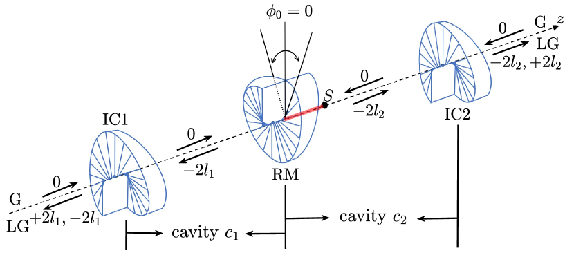
In our scheme, we consider a double LG rotational-cavity optomechanical system shown in Fig. 1, which consists of two input couplers (IC1 and IC2) and a rotational mirror (RM). IC1 (IC2) and RM are all spiral phase elements, which can modify the azimuthal structure of laser beams [3, 4]. RM can be seen as a thin disk with the moment of inertia ( and being its mass and radius). We assume that the input fields injected to the system are all Gaussian (G) fields with topological charge 0, whose charges do not change when passing through IC1 and IC2 while the reflected components gain a charge and . In addition, by changing the step height on both sides of RM or the optical wavelength [4], RM can remove a topological charge () from the beams in cavity (cavity ). The related cavity conditions have been discussed in detail in Refs. [25, 31, 32].
In our system, the two cavities are assumed to have the same resonance frequency . Cavity is driven by a strong driving field of frequency and amplitude and probed by a weak probe field of frequency and amplitude . Meanwhile, another driving field of frequency and amplitude is injected to cavity . In a rotating frame with respect to the driving fields, the Hamiltonian of system can be written as
| (1) |
in which and are the bosonic annihilation (creation) operators of the two cavity modes, respectively, satisfying the commutation relation . and are the frequency detunings of the driving fields from the cavity modes and the probe field. and denote the angular momentum of RM about the cavity axis and the angular displacement with the commutation relation , and is the angular rotation frequency. characterize the optorotational coupling between two LG cavity modes and RM [25, 31, 32], with and being the speed of light in vacuum and the length of the cavity. The last two terms describe the coupling between the input fields and the two cavity modes with amplitudes and . and are the corresponding decay rates of the two cavities and the powers of input fields.
Our scheme focuses on the mean response of the system to the probe field, so we consider the mean-value equations of the system, which can be obtained by deriving the Heisenberg equations of the system operators as well as adding the corresponding damping terms. By using the factorization assumption [22], the mean value equations of the system operators can be derived as follows,
| (2) | ||||
| (3) | ||||
| (4) |
in which is the damping rate of RM.
The above mean value equations are nonlinear equations, but it can be solved by using the perturbation method due to the fact that the driving fields are much stronger than the probe field. By setting , one can obtain the steady-state values of the corresponding dynamical variables as
| (5) | ||||
| (6) | ||||
| (7) | ||||
| (8) |
in which represents the effective detuning of cavity from the driving fields. One can find that the effective detuning of cavity can be modulated effectively by cavity . Besides, this modulation can be improved if we choose a cavity with higher cavity finesse and stronger driving power, as well as a mirror with smaller mass and size. Meanwhile, the resonantly driven cavity can also greatly enhance its modulation effect on cavity .
Besides, the equations of the corresponding perturbation terms can be derived as follows,
| (9) | ||||
| (10) | ||||
| (11) |
The above equations of the perturbation terms can be solved by applying the ansatz, i.e., , then, one can get the solution of , which corresponds to the response of the system to the probe field [22, 37].
| (12) |
with
| (13) | ||||
| (14) | ||||
| (15) | ||||
| (16) |
III Transmission spectrum of the probe field in the double LG rotational cavity
In this section, we will study the response of double LG rotational cavity to the probe field, and compare it with the case of the single LG rotational cavity. The parameters used in our paper are chosen from Refs. [25, 31, 32]. For RM, the radius , the mass , the angular frequency , and the mechanical quality factor . For cavity, the cavity length mm, the cavity finesse , and cavity is driven with red-detuned driving (i.e., , and the frequency of driving field is with wavelength ); meanwhile, cavity is driven resonantly with the effective detuning . We would point out that cavity with red-detuned driving can exhibit bistability for a strong enough driving field [39, 40], however, the parameters used in our paper are chosen in the area of monostability.
Due to the presence of the optorotational coupling, the OMIT phenomenon can be generated in the single LG rotational cavity, and based on the correlation between the window width and the topological charge, OAM can be measured in principle [24]. But, we would like to point out that only the magnitude of OAM can be measured in a standard single LG rotational cavity. This is due to the fact that the effective cavity detuning of the single LG rotational cavity is only related to the magnitude of OAM and not to its sign, which can be seen from Eq. (7) of our paper [this equation is simplified as for the single LG rotational cavity], and Eq. (4) of Ref. [24]. For the double LG rotational-cavity system of our scheme, however, the effective detuning of cavity can be modulated by cavity , i.e., the second term of Eq. (7), , which leads to that for different signs of OAM, the effective detuning of cavity will be modulated differently, as shown in the following sections.
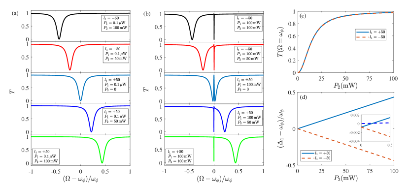
At first, we study the transmission characteristics of the probe field in the double LG rotational cavity. The transmission spectrum of the probe field in the double LG rotational cavity is plotted as a function of the normalized detuning , as shown in Figs. 2(a) and 2(b). From the curves of Fig. 2(a), one can see that for a weak driving field of cavity with power W, the Lorentzian-shaped transmission spectrum originally located at the frequency shifts obviously with the increase of the driving field of cavity . What’s more, for different signs of OAM carried by the beams in cavity , the direction of the spectral shift is just opposite. Specifically, for the topological charge , the transmission spectrum shifts to the right, but for , it shifts to the left. Thus, this spectral shift can be served as a fully switchable light switch through adjusting the power of the driving field, as shown in Fig. 2(c). Besides, one can find from the curves of Fig. 2(b) that for a stronger driving field of cavity with power mW, a symmetrical OMIT window occurs in the frequency close to resonance, but this symmetry is broken once cavity is introduced, then an asymmetric window similar to the Fano resonance can be observed. Like the Lorentzian-shaped transmission spectrum [see Fig. 2(a)], the asymmetric transparency window also has a strong correlation with the OAM carried by the beams in cavity . This transmission characteristics of the probe field in our system can not be realized with the standard single LG rotational cavity [24].
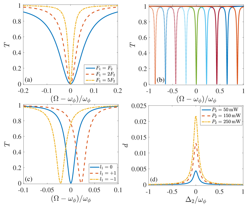
This correlation can be understood based on the dependence of the effective detuning of cavity on the cavity . As shown in Fig. 2(d), we plot the normalized cavity detuning as a function of the driving power . From Fig. 2(d), one can clearly see that the effective detuning of cavity strongly depends on the driving power of cavity , where for different signs of OAM it changes in reverse with the increase of the driving field. Meanwhile, one can also find from the inset of Fig. 2(d) that when the value of the driving power of cavity is zero, the value of the normalized cavity detuning of cavity isn’t zero, which is due to the existence of the optorotational coupling of cavity . Furthermore, the curves of Fig. 2(d) show that the value of the normalized cavity detuning is consistent with the position of the resonance valley of the transmission spectrum. Thus, there is a strong correlation between the spectral shift and the OAM carried by the beams of cavity in our system. In addition, the linewidth of the transmission spectrum of the probe field in our system can be decreased by choosing the cavity with a high cavity finesse, as shown in Fig. 3(a), which will contribute to measuring the OAM with a higher resolution. The above directional spectral shift induced by cavity gives us the inspiration of measuring both the magnitude and sign of OAM simultaneously.
IV Measurement of the magnitude and sign of orbital angular momentum
In this section, we apply the directional spectral shift induced by cavity to measure the magnitude and sign of OAM. As shown in Figs. 3(b) and 3(c), the transmission spectrum of the probe field is plotted as a function of the normalized detuning for a wide range of OAM. One can observe from the curves that for a fixed driving power of the system, the Lorentzian-shaped transmission spectrum can show a significant spectral shift when we increase the magnitude of OAM. Specifically, for OAM with positive sign, the resonance valley of the transmission spectrum shifts to the right with the increase of the magnitude of OAM, and for OAM with negative sign, the situation is exactly the opposite. Moreover, one can also observe in Fig 3(c) that our method can distinguish OAM with by monitoring the shift of the transmission spectrum. As expected, based on the shift of the transmission spectrum of the probe field in a double LG rotational-cavity system, the magnitude and sign of OAM can be simultaneously measured compared with the case of the single LG rotational-cavity system in Ref. [24]. Utilizing the spectral shift of the transmission spectrum to measure OAM, in addition to the linewidth of the transmission spectrum, the distance of the spectral shift caused by the change of OAM is also an important index. As shown in Eq. (7), the distance of the spectral shift in our scheme can be enhanced by the resonantly driven cavity with a strong driving power. This comes from the fact that the intracavity photon number in cavity can be increased dramatically in this case, which can enhance its modulation effect on cavity . The distance of the spectral shift caused by the OAM change with is plotted as a function of the normalized detuning , as shown in Fig. 3(d). One can see that the distance of the spectral shift can get its maximum value at the resonance frequency , and the maximum value can be increased by the driving power . Then, with the optimized distance of the spectral shift and its linewidth, our method can distinguish OAM with a higher sensitivity.
Thus, based on the correlation between position of the resonance valley and OAM, we can measure the magnitude and sign of OAM simultaneously. The position of the resonance valley can be determined by the following conditions,
| (18) |
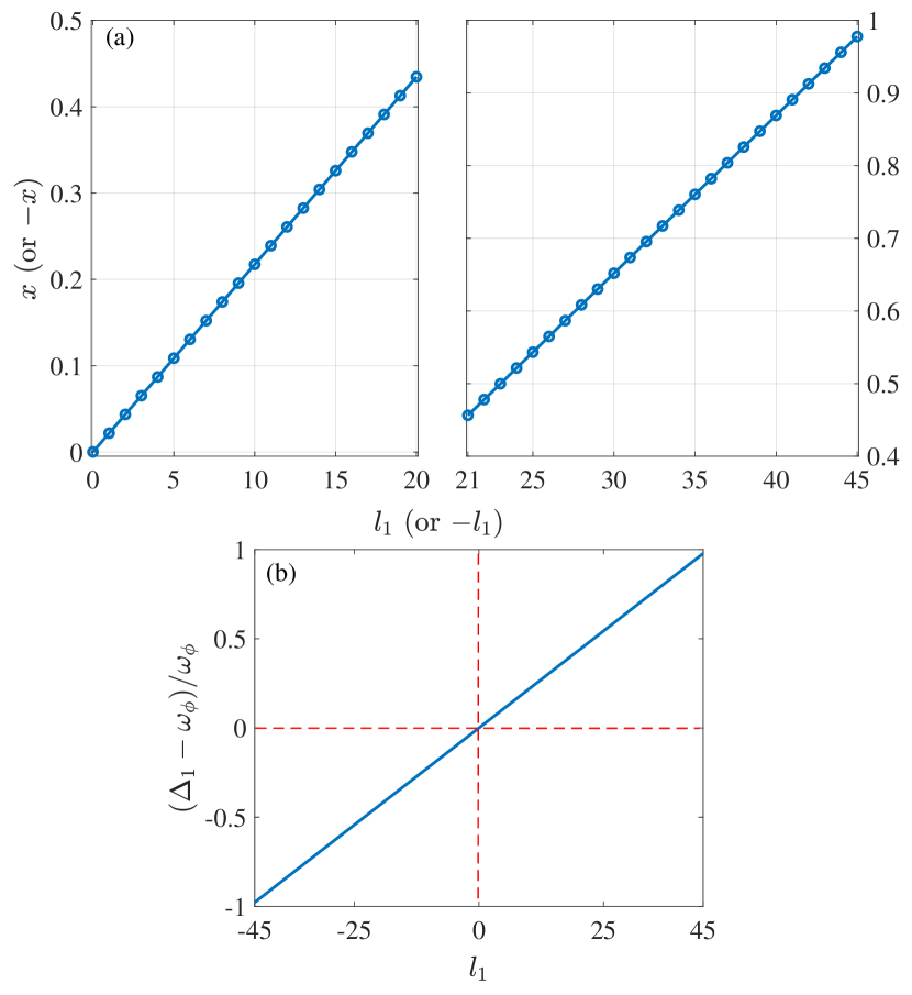
with corresponding to the position of the resonance valley. In order to clearly show this correlation, we plot the position of the resonance valley as a function of the magnitude and sign of OAM, as shown in Fig. 4(a), where the topological charge value changes in integer. Figure 4(a) shows that there is an almost linear relationship between the position of the resonance valley and the magnitude of OAM. Meanwhile, for the positive and negative signs of OAM, the position is basically symmetrical about the resonance frequency , which is different from Fig. 5 of Ref. [24], where only the magnitude of OAM can be measured. Moreover, with the spectral shift in our system, the measurable topological charge is up to . This spectral shift with the magnitude and sign of OAM can be understood with the effective detuning of cavity , i.e., Eq. (7). As shown in Fig. 4(b), the normalized cavity detuning of cavity is plotted as a function of the OAM. One can find that there is an almost linear relationship between the value of the normalized cavity detuning and the magnitude of OAM, and the trend of the normalized cavity detuning with OAM (including its magnitude and sign) is consistent with Fig. 4(a).
Based on the above analysis, by monitoring the shift of the transmission spectrum of the probe field in a double LG rotational-cavity system, our scheme can measure a wider range of OAM with distinguishable sign compared with the case of the single LG rotational cavity in Ref. [24]. Meanwhile, the sensitivity of our scheme can be improved by optimizing the distance of the spectral shift and its linewidth, which is a significant improvement for measuring OAM in optomechanics.
V Conclusions
In summary, we have investigated the transmission characteristics of the probe field in the double LG rotational cavity and showed that the effective cavity detuning in this system depends on the magnitude and sign of OAM simultaneously, which is different from the case of the single LG rotational cavity. Moreover, we found that the transmission spectrum of the probe field has a strong correlation with the magnitude and sign of OAM. Specifically, for different magnitudes of OAM, the transmission spectrum can show an obvious spectral shift, meanwhile, the spectral shift is directional for different signs of OAM. Thus, based on this feature, we propose a scheme to measure OAM including the magnitude and the sign, in which the measurable topological charge is up to . This work solves the shortcoming of the inability to distinguish the sign of OAM in optomechanics.
acknowledgments
This work was supported by the National Key Research and Development Program of China (Grants No. 2017YFA0304202 and No. 2017YFA0205700), the National Natural Science Foundation of China (NSFC) (Grants No. 11875231 and No. 11935012), and the Fundamental Research Funds for the Central Universities through Grant No. 2018FZA3005.
References
- Nye and Berry [1974] J. F. Nye and M. V. Berry, Dislocations in wave trains, Proc. R. Soc. A 336, 165 (1974).
- Allen et al. [1992] L. Allen, M. W. Beijersbergen, R. J. C. Spreeuw, and J. P. Woerdman, Orbital angular momentum of light and the transformation of laguerre-gaussian laser modes, Phys. Rev. A 45, 8185 (1992).
- Beijersbergen et al. [1994] M. W. Beijersbergen, R. P. C. Coerwinkel, M. Kristensen, and J. P. Woerdman, Helical-wavefront laser beams produced with a spiral phaseplate, Opt. Commun. 112, 321 (1994).
- Oemrawsingh et al. [2004] S. S. R. Oemrawsingh, E. R. Eliel, J. P. Woerdman, E. J. K. Verstegen, J. G. Kloosterboer, and G. W. T. Hooft, Half-integral spiral phase plates for optical wavelengths, J. Opt. A: Pure Appl. Opt. 6, S288 (2004).
- Bazhenov et al. [1992] V. Y. Bazhenov, M. S. Soskin, and M. V. Vasnetsov, Screw dislocations in light wavefronts, J. Mod. Opt. 39, 985 (1992).
- Basistiy et al. [1993] I. V. Basistiy, V. Y. Bazhenov, M. S. Soskin, and M. V. Vasnetsov, Optics of light beams with screw dislocations, Opt. Commun. 103, 422 (1993).
- Zhang et al. [2020] Z. Zhang et al., Tunable topological charge vortex microlaser, Science 368, 760–763 (2020).
- Ji et al. [2020] Z. Ji et al., Photocurrent detection of the orbital angular momentum of light, Science 368, 763–767 (2020).
- Ding et al. [2015] D. S. Ding et al., Quantum storage of orbital angular momentum entanglement in an atomic ensemble, Phys. Rev. Lett. 114, 050502 (2015).
- Wang et al. [2012] J. Wang et al., Terabit free-space data transmission employing orbital angular momentum multiplexing, Nat. Photon. 6, 488 (2012).
- Bozinovic et al. [2013] N. Bozinovic et al., Terabit-scale orbital angular momentum mode division multiplexing in fibers, Science 340, 1545 (2013).
- Chen et al. [2013] M. Chen, M. Mazilu, Y. Arita, E. M. Wright, and K. Dholakia, Dynamics of microparticles trapped in a perfect vortex beam, Opt. Lett. 38, 4919 (2013).
- Padgett and Bowman [2011] M. J. Padgett and R. Bowman, Tweezers with a twist, Nat. Photon. 5, 343 (2011).
- Gecevicius et al. [2014] M. Gecevicius, R. Drevinskas, M. Beresna, and P. G. Kazansky, Single beam optical vortex tweezers with tunable orbital angular momentum, Appl. Phys. Lett. 104, 231110 (2014).
- Harris et al. [1994a] M. Harris, C. A. Hill, and J. M. Vaughan, Optical helices and spiral interference fringes, Opt. Commun. 106, 161 (1994a).
- Harris et al. [1994b] M. Harris, C. A. Hill, P. R. Tapster, and J. M. Vaughan, Laser modes with helical wave fronts, Phys. Rev. A 49, 3119 (1994b).
- Hickmann et al. [2010] J. M. Hickmann, E. J. S. Fonseca, W. C. Soares, and S. Chavez-Cerda, Unveiling a truncated optical lattice associated with a triangular aperture using light’s orbital angular momentum, Phys. Rev. Lett. 105, 053904 (2010).
- Guo et al. [2009] C. S. Guo, L. L. Lu, and H. T. Wang, Characterizing topological charge of optical vortices by using an annular aperture, Opt. Lett. 34, 3686 (2009).
- Vaity et al. [2013] P. Vaity, J. Banerji, and R. P. Singh, Measuring the topological charge of an optical vortex by using a tilted convex lens, Phys. Lett. A 377, 1154 (2013).
- Zheng and Wang [2017] S. Zheng and J. Wang, Measuring orbital angular momentum (oam) states of vortex beams with annular gratings, Sci. Reports 7, 40781 (2017).
- Harris [1997] S. E. Harris, Electromagnetically induced transparency, Phys. Today 50, 36 (1997).
- Agarwal and Huang [2010] G. S. Agarwal and S. Huang, Electromagnetically induced transparency in mechanical effects of light, Phys. Rev. A 81, 041803(R) (2010).
- Weis et al. [2010] S. Weis, R. Riviere, S. Deleglise, E. Gavartin, O. Arcizet, A. Schliesser, and T. J. Kippenberg, Optomechanically induced transparency, Science 330, 1520 (2010).
- Peng et al. [2019] J. X. Peng, Z. Chen, Q. Z. Yuan, and X. L. Feng, Optomechanically induced transparency in a laguerre-gaussian rotational-cavity system and its application to the detection of orbital angular momentum of light fields, Phys. Rev. A 99, 043817 (2019).
- Bhattacharya and Meystre [2007] M. Bhattacharya and P. Meystre, Using a laguerre-gaussian beam to trap and cool the rotational motion of a mirror, Phys. Rev. Lett. 99, 153603 (2007).
- Aspelmeyer et al. [2014] M. Aspelmeyer, T. J. Kippenberg, and F. Marquardt, Cavity optomechanics, Rev. Mod. Phys. 86, 1391 (2014).
- Law [1995] C. K. Law, Interaction between a moving mirror and radiation pressure: A hamiltonian formulation, Phys. Rev. A 51, 2537 (1995).
- Bhattacharya et al. [2008a] M. Bhattacharya, H. Uys, and P. Meystre, Optomechanical trapping and cooling of partially reflective mirrors, Phys. Rev. A 77, 033819 (2008a).
- Xiao et al. [2014] Y. Xiao, Y. F. Yu, and Z. M. Zhang, Controllable optomechanically induced transparency and ponderomotive squeezing in an optomechanical system assisted by an atomic ensemble, Opt. Express 22, 17979 (2014).
- Zhang and Wang [2020] Z. Zhang and X. Wang, Photon-assisted entanglement and squeezing generation and decoherence suppression via a quadratic optomechanical coupling, Opt. Express 28, 2732 (2020).
- Bhattacharya et al. [2008b] M. Bhattacharya, P. L. Giscard, and P. Meystre, Entanglement of a laguerre-gaussian cavity mode with a rotating mirror, Phys. Rev. A 77, 013827 (2008b).
- Bhattacharya et al. [2008c] M. Bhattacharya, P. L. Giscard, and P. Meystre, Entangling the rovibrational modes of a macroscopic mirror using radiation pressure, Phys. Rev. A 77, 030303(R) (2008c).
- Chen et al. [2019] Z. Chen, J. X. Peng, J. J. Fu, and X. L. Feng, Entanglement of two rotating mirrors coupled to a single laguerre-gaussian cavity mode, Opt. Express 27, 29479 (2019).
- Liu et al. [2018] Y. M. Liu, C. H. Bai, D. Y. Wang, T. Wang, M. H. Zheng, H. F. Wang, A. D. Zhu, and S. Zhang, Ground-state cooling of rotating mirror in double-laguerre-gaussian-cavity with atomic ensemble, Opt. Express 26, 6143 (2018).
- Peng et al. [2020] J. X. Peng, Z. Chen, Q. Z. Yuan, and X. L. Feng, Double optomechanically induced transparency in a laguerre-gaussian rovibrational cavity, Phys. Lett. A 384, 126153 (2020).
- Sanavio et al. [2020] C. Sanavio, J. Z. Bernad, and A. Xuereb, Fisher information based estimation of optomechanical coupling strengths, Phys. Rev. A 102, 013508 (2020).
- Huang and Agarwal [2010] S. Huang and G. S. Agarwal, Normal-mode splitting and antibunching in stokes and anti-stokes processes in cavity optomechanics: Radiation-pressure-induced four-wave-mixing cavity optomechanics, Phys. Rev. A 81, 033830 (2010).
- Gardiner and Zoller [2004] C. W. Gardiner and P. Zoller, Quantum noise: a handbook of Markovian and non-Markovian quantum stochastic methods with applications to quantum optics (Springer-Verlag, 2004).
- Mccullen et al. [1984] J. D. Mccullen, P. Meystre, and E. M. Wright, Mirror confinement and control through radiation pressure, Opt. Lett. 9, 193 (1984).
- Baas et al. [2004] A. Baas, J. P. Karr, H. Eleuch, and E. Giacobino, Optical bistability in semiconductor microcavities, Phys. Rev. A 69, 023809 (2004).