A method to measure superconducting transition temperature of microwave kinetic inductance detector by changing power of readout microwaves
Abstract
A microwave kinetic inductance detector (MKID) is a cutting-edge superconducting detector, and its principle is based on a superconducting resonator circuit. The superconducting transition temperature () of the MKID is an important parameter because various MKID characterization parameters depend on it. In this paper, we propose a method to measure the of the MKID by changing the applied power of the readout microwaves. A small fraction of the readout power is deposited in the MKID, and the number of quasiparticles in the MKID increases with this power. Furthermore, the quasiparticle lifetime decreases with the number of quasiparticles. Therefore, we can measure the relation between the quasiparticle lifetime and the detector response by rapidly varying the readout power. From this relation, we estimate the intrinsic quasiparticle lifetime. This lifetime is theoretically modeled by , the physical temperature of the MKID device, and other known parameters. We obtain by comparing the measured lifetime with that acquired using the theoretical model. Using an MKID fabricated with aluminum, we demonstrate this method at a operation. The results are consistent with those obtained by measured by monitoring the transmittance of the readout microwaves with the variation in the device temperature. The method proposed in this paper is applicable to other types, such as a hybrid-type MKID.
A superconducting detector is a sensitive device because its gap energy is much smaller than that of a semiconductor detector. A microwave kinetic inductance detector (MKID) Day et al. (2003) is a superconducting microwave resonator. This resonant circuit is fabricated of a thin superconductor film on a silicon or sapphire substrate. The resonant frequency is tuned by the total length of the resonator. Therefore, numerous detectors can be read by multi-frequency tones using the same readout line. This advantage allows the production of a large MKID array, such as one containing 100–1000 detectors per single readout line. This has resulted in the rapid progress of radio and infrared astronomical observations Endo et al. (2019); Monfardini et al. (2010); Galitzki et al. (2014); Nagasaki et al. (2018).
An MKID has a simple detection mechanism. Radiation entering the detector breaks a Cooper pair in the resonator when the radiation energy is larger than twice the gap energy of the superconducting film. A broken Cooper pair yields two additional quasiparticles. The inductance of the MKID circuit varies with the number of quasiparticles, and the resonant condition of this MKID changes with the inductance. We can measure entering radiation energy using the variation in the resonant phase and amplitude.
The superconducting transition temperature () of the MKID is an important parameter. This is because various MKID characterization parameters depend on . In this paper, we propose a method to measure the of the MKID by changing the readout power rapidly.
According to the BCS theory Bardeen, Cooper, and Schrieffer (1957), the relation between the gap energy (), and is given by following formula:
| (1) |
where is the Boltzmann constant. Using , the number of quasiparticles () under a low-temperature condition (i.e. , where is the device temperature) is obtained by the following formula Bardeen, Cooper, and Schrieffer (1957):
| (2) |
where is the single-spin density of states at the Fermi level ( for an aluminum McMillan (1968)), and is the volume of the resonator. The intrinsic quasiparticle lifetime, (), is obtained by the following formula Kaplan et al. (1976):
| (3) |
where is the electron–phonon interaction time ( for an aluminum MKIDDe Visser et al. (2011)). The noise equivalent power derived from the generation and recombination of the quasiparticles () is obtained by the following formulaSergeev, Mitin, and Karasik (2002):
| (4) |
where is the pair breaking efficiency Kurakado (1982) ( for aluminumKozorezov et al. (2000)).
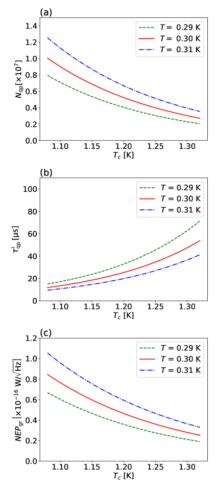
Figure 1 presents the parameters of an aluminum MKID as a function of , where we display the plots of the device temperature at approximately . They are sensitive to . Various previous studies have used different , with the deviation being approximately De Visser et al. (2011); Fyhrie et al. (2020); Vissers et al. (2020). Understanding the reason of this difference is a recent research topic, e.g., Fyhrie Fyhrie et al. (2020) discusses the relation between and film thickness.
Monitoring the transmittance of the readout microwaves with the device temperature variation is a conventional method to measure the of an MKIDMazin (2005); Dominjon et al. (2016). This method is referred as the "S21 method" in this paper. Note that this method is not applicable for a hybrid-type MKID Noroozian et al. (2009); Yates et al. (2011).
Another method estimates using the power spectrum density (), which is modeled by the following formula de Visser (2014):
| (5) |
where subscript denotes the phase or amplitude response, is the quasiparticle lifetime under the measurement condition, is the frequency of the detector response and is the noise of the readout system. is the resonator ring time given by (where is the quality factor of the resonance and is the resonant frequency). We extract by fitting the power spectrum density with the above formula. Under the assumption of , we obtain using Eq. (3). This method requires that is lower than the contribution of the first term in Eq (5). Moreover, another contribution due to a two level system noiseGao et al. (2007) should be low enough in the case of the phase response.
We propose the third method to measure , which uses a loss of the readout microwaves in the MKID. The quasiparticle lifetime () decreases with the increase of the number of additional quasiparticles () produced by the readout power loss de Visser (2014); Thompson et al. (2013); De Visser et al. (2012, 2014); Zmuidzinas and Richards (2004):
| (6) |
Because the phase response () of the MKID is proportional to the number of additional quasiparticles Gao et al. (2008), the above formula is rewritten by:
| (7) |
where . This suggests that can be estimated from the relation between and Zmuidzinas and Richards (2004); Gao et al. (2008). This relation is easily measured using our previous method to measure the phase responsivityKutsuma et al. (2019). A small fraction of the readout power is deposited in the MKID, and the response of the MKID increases with this power. In this paper, we demonstrate the measurement of this relation for an aluminum MKID. Subsequently, we obtain with Eq. (3) and estimate .
Figure 2 presents the diagram of the MKID readout.
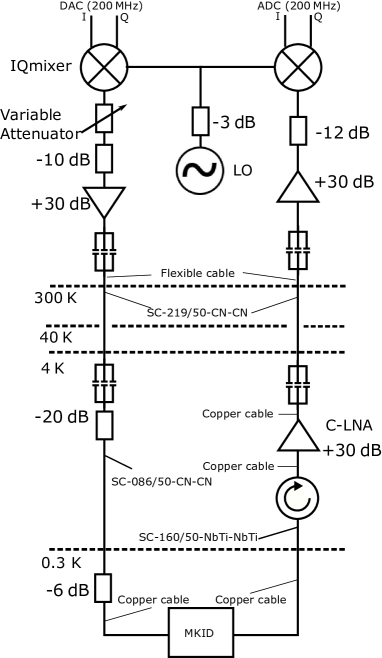
Our cryostat (Niki Glass Co., Ltd.) consists of , and thermal shields from inside to outside. They are insulated from the room temperature () in a vacuum chamber and are cooled using a pulse tube refrigerator (PT407RM, Cryomech Co. LTD). The thermal shield also acts as a magnetic shield (A4K, Amuneal Co. LTD) for mitigating the effects of geomagnetism. The MKID device is set in a light-tight copper box. The box is cooled by a -sorption refrigerator, and it is maintained at with an accuracy of .
The MKID device is fabricated at RIKEN. This device consists of a quarter-wave coplanar waveguide resonator and a feedline (there is no coupling with any antenna). The width of the center strip and gap of the resonator (the feedline) are () and (), respectively. All the circuits patterns are formed using an aluminum film on a silicon wafer. The volume of the resonator is (the width is , the length is , and the thickness is ). Its resonant frequency and quality factor are and , respectively. Our readout system Ishitsuka et al. (2016); Suzuki et al. (2018) measures the response based on a direct down-conversion logic with a sampling speed, and the data are down-sampled to a step. The power of the readout microwave is controlled by a variable attenuator (LDA-602, Vaunix Co. LTD). It requires a few microseconds to change the attenuation value.
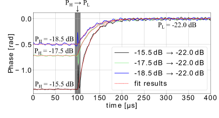
We use eight attenuation setups to change the readout power from high power () to low power (), as summarized in Table 1. The readout power into the feedline is approximately at . We use the same treatment for the effects of a cable delay and linearity correction as described in the reference Kutsuma et al., 2019. Figure 3 shows the phase response as a function of time.
We reset the attenuation value at . We fit the data to Eq. (5) in the reference Kutsuma et al., 2019, and we obtain the phase response () and the quasiparticle lifetime () for each setup using Eq.(7). We mask the data in the short period, , because of the uncontrolled state of attenuation soon after the reset. We measure 50 samples for each set of power change. Table 1 summarizes the fitted results for each setup.
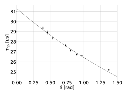
Subsequently, we obtain using Eq. (3), where we only estimate the statistical error. We estimate the systematic uncertainties for ; device temperature (), time for changing the attenuation value (), and electron-phonon interaction time (). We finally obtain , including the systematic error.
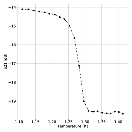
For comparison, we also measure by the S21 method. Figure 5 presents the S21 intensity results at as a function of the device temperature. We determine as a temperature at the middle of the transition, . Here, the error includes the difference from the onset of the superconducting transition and the uncertainty of the thermometer. We confirm the consistency in the results from the two methods.
In summary, we propose a method to measure the of an MKID device by changing the power of the readout microwaves. In this method, we obtain the intrinsic quasiparticle lifetime using the device temperature. Subsequently, we estimate using them. We demonstrate our method using an aluminum MKID maintained at . We obtain . This result is consistent with the conventional method: monitoring the microwave transmittance by changing the device temperature, . The method proposed in this paper is applicable to other types, such as a hybrid-type MKID.
This work was supported by the JRA program in RIKEN and Grants-in-Aid for Scientific Research from The Ministry of Education, Culture, Sports, Science and Technology, Japan (KAKENHI Grants 19H05499, 15H05743, 16J09435, and R2804). We thank Prof. Koji Ishidoshiro for lending us the cryostat used in this paper. We acknowledge Prof. Masato Naruse for the MKID design. We acknowledge Mr. Noboru Furukawa for the MKID fabrication. We thank Dr. Shunsuke Honda for useful discussions. OT acknowledges support from the Heiwa-Nakajima Foundation, US-Japan Science Technology Cooperation Program, and SPIRITS grant.
The data that support the findings of this study are available from the corresponding author upon reasonable request.
References
- Day et al. (2003) P. K. Day, H. G. LeDuc, B. A. Mazin, A. Vayonakis, and J. Zmuidzinas, Nature 425, 817–821 (2003).
- Endo et al. (2019) A. Endo, K. Karatsu, Y. Tamura, T. Oshima, A. Taniguchi, T. Takekoshi, S. Asayama, T. J. Bakx, S. Bosma, J. Bueno, et al., Nature Astronomy 3, 989–996 (2019).
- Monfardini et al. (2010) A. Monfardini, L. Swenson, A. Bideaud, F. Désert, S. Yates, A. Benoit, A. Baryshev, J. Baselmans, S. Doyle, B. Klein, et al., Astronomy & Astrophysics 521, A29 (2010).
- Galitzki et al. (2014) N. Galitzki, P. A. Ade, F. E. Angilè, P. Ashton, J. A. Beall, D. Becker, K. J. Bradford, G. Che, H.-M. Cho, M. J. Devlin, et al., Journal of Astronomical Instrumentation 3, 1440001 (2014).
- Nagasaki et al. (2018) T. Nagasaki, J. Choi, R. Génova-Santos, M. Hattori, M. Hazumi, H. Ishitsuka, K. Karatsu, K. Kikuchi, R. Koyano, H. Kutsuma, et al., Journal of Low Temperature Physics 193, 1066–1074 (2018).
- Bardeen, Cooper, and Schrieffer (1957) J. Bardeen, L. N. Cooper, and J. R. Schrieffer, Physical review 108, 1175 (1957).
- McMillan (1968) W. McMillan, Physical Review 167, 331 (1968).
- Kaplan et al. (1976) S. Kaplan, C. Chi, D. Langenberg, J.-J. Chang, S. Jafarey, and D. Scalapino, Physical Review B 14, 4854 (1976).
- De Visser et al. (2011) P. De Visser, J. Baselmans, P. Diener, S. Yates, A. Endo, and T. Klapwijk, Physical review letters 106, 167004 (2011).
- Sergeev, Mitin, and Karasik (2002) A. Sergeev, V. Mitin, and B. Karasik, Applied physics letters 80, 817–819 (2002).
- Kurakado (1982) M. Kurakado, Nuclear Instruments and Methods in Physics Research 196, 275–277 (1982).
- Kozorezov et al. (2000) A. Kozorezov, A. Volkov, J. Wigmore, A. Peacock, A. Poelaert, and R. Den Hartog, Physical Review B 61, 11807 (2000).
- Fyhrie et al. (2020) A. Fyhrie, P. Day, J. Glenn, H. Leduc, C. McKenney, J. Perido, and J. Zmuidzinas, Journal of Low Temperature Physics , 1–8 (2020).
- Vissers et al. (2020) M. Vissers, J. Austermann, M. Malnou, C. McKenney, B. Dober, J. Hubmayr, G. Hilton, J. Ullom, and J. Gao, Applied Physics Letters 116, 032601 (2020).
- Mazin (2005) B. A. Mazin, Microwave kinetic inductance detectors, Ph.D. thesis, California Institute of Technology (2005).
- Dominjon et al. (2016) A. Dominjon, M. Sekine, K. Karatsu, T. Noguchi, Y. Sekimoto, S. Shu, S. Sekiguchi, and T. Nitta, IEEE Transactions on Applied Superconductivity 26, 1–6 (2016).
- Noroozian et al. (2009) O. Noroozian, J. Gao, J. Zmuidzinas, H. G. LeDuc, and B. A. Mazin, in AIP Conference Proceedings, Vol. 1185 (American Institute of Physics, 2009) pp. 148–151.
- Yates et al. (2011) S. Yates, J. Baselmans, A. Endo, R. Janssen, L. Ferrari, P. Diener, and A. Baryshev, Applied Physics Letters 99, 073505 (2011).
- de Visser (2014) P. J. de Visser, Quasiparticle dynamics in aluminium superconducting microwave resonators, Ph.D. thesis, Delft University of Technology (2014).
- Gao et al. (2007) J. Gao, J. Zmuidzinas, B. A. Mazin, H. G. LeDuc, and P. K. Day, Applied Physics Letters 90, 102507 (2007).
- Thompson et al. (2013) S. Thompson, S. Withington, D. Goldie, and C. Thomas, Superconductor Science and Technology 26, 095009 (2013).
- De Visser et al. (2012) P. De Visser, J. Baselmans, S. Yates, P. Diener, A. Endo, and T. Klapwijk, Applied Physics Letters 100, 162601 (2012).
- De Visser et al. (2014) P. De Visser, D. Goldie, P. Diener, S. Withington, J. Baselmans, and T. Klapwijk, Physical review letters 112, 047004 (2014).
- Zmuidzinas and Richards (2004) J. Zmuidzinas and P. L. Richards, Proceedings of the IEEE 92, 1597–1616 (2004).
- Gao et al. (2008) J. Gao, J. Zmuidzinas, A. Vayonakis, P. Day, B. Mazin, and H. Leduc, Journal of Low Temperature Physics 151, 557–563 (2008).
- Kutsuma et al. (2019) H. Kutsuma, M. Hattori, R. Koyano, S. Mima, S. Oguri, C. Otani, T. Taino, and O. Tajima, Applied Physics Letters 115, 032603 (2019).
- Ishitsuka et al. (2016) H. Ishitsuka, M. Ikeno, S. Oguri, O. Tajima, N. Tomita, and T. Uchida, Journal of Low Temperature Physics 184, 424–430 (2016).
- Suzuki et al. (2018) J. Suzuki, H. Ishitsuka, K. Lee, S. Oguri, O. Tajima, N. Tomita, and E. Won, Journal of Low Temperature Physics 193, 562–569 (2018).