Off-axis dipole forces in optical tweezers by an optical analog of the Magnus effect
Abstract
It is shown that a circular dipole can deflect the focused laser beam that induces it, and will experience a corresponding transverse force. Quantitative expressions are derived for Gaussian and angular tophat beams, while the effects vanish in the plane-wave limit. The phenomena are analogous to the Magnus effect pushing a spinning ball onto a curved trajectory. The optical case originates in the coupling of spin and orbital angular momentum of the dipole and the light. In optical tweezers the force causes off-axis displacement of the trapping position of an atom by a spin-dependent amount up to , set by the direction of a magnetic field. This suggests direct methods to demonstrate and explore these effects, for instance to induce spin-dependent motion.
A common practice in many branches of sports is to send a ball onto a curved trajectory by giving it a spin. In this famous example of the Magnus effect Magnus (1853) the spinning ball deflects the stream of air around it, and is pushed sideways by the reaction force perpendicular to its forward velocity. In analogy, we may ask if a rotating dipole in an atom may similarly deflect a beam of light, and thereby be pushed by a force perpendicular to the light beam. C.G. Darwin already remarked that for circular dipoles “…the wave front of the emitted radiation faces not exactly away from the origin, but from a point about a wave-length away from it.”Darwin (1932). A recent experiment confirmed that an atomic circular dipole can indeed appear to be displaced from its true location, due to the emitted spiral-shaped wavefront Araneda et al. (2019). Circular dipoles provide perhaps the simplest example of the intrinsic coupling of spin and orbital angular momentum (SAM and OAM, respectively) in non-paraxial light fields Allen et al. (1992); Bliokh and Nori (2015); van Enk and Nienhuis (1994); Dorn et al. (2003); Nieminen et al. (2008); Monteiro et al. (2009); Bliokh et al. (2010); Rodríguez-Herrera et al. (2010); Bliokh et al. (2011); Angelsky et al. (2012). Such fields, in the form of tightly focused laser beams, are of central importance in a rapidly growing range of experiments involving (arrays of) optical tweezers Thompson et al. (2013); Barredo et al. (2016); Endres et al. (2016); Bernien et al. (2017); Cooper et al. (2018); Norcia et al. (2018); Pagano et al. (2019); Jackson et al. (2020); Anderegg et al. (2019); Saskin et al. (2019); Wang et al. (2020). These are developed as precise tools to hold and manipulate single atoms or molecules at the quantum level, in creating platforms for quantum simulation and computation, as well as for quantum sensing and atomic clocks Madjarov et al. (2019); Norcia et al. (2019).

Here we predict that an atomic circular dipole can deflect the centered focused laser beam that induces it. Conversely, the atom will experience a transverse force when on-axis 111See also Dooghin et al. (1992) for a very different kind of analogy of the Magnus effect.. An important consequence of this force can be seen in the off-axis displacement of the trapping potential created by an optical tweezer Wang et al. (2020). Thus, rather than ‘seeing an atom where it is not’ Araneda et al. (2019); Schwartz and Dogariu (2006); Arnoldus et al. (2008), here we describe its counterpart of ‘trapping an atom where the focus is not’ Thompson et al. (2013); Wang et al. (2020); Caldwell and Tarbutt (2020). A simple geometric argument based on light scattering shows that the true displacement of the trapping potential is in fact a direct consequence of the apparent displacement of an emitting circular dipole Darwin (1932); Araneda et al. (2019). Tweezer trap displacements have previously been calculated numerically, for specific beam shapes, in terms of vector and tensor light shifts Thompson et al. (2013); Caldwell and Tarbutt (2020). The geometric argument given here directly shows that for a circular dipole the displacement is simply , and is remarkably independent of many parameters, including the laser detuning, trap frequency, and even the detailed shape of the trap. A comparison of a Gaussian beam with an angular tophat beam illustrates this. This profound insight provides the basis for state-dependent manipulation of atomic motion within the tweezer.
We describe these effects in terms of interference between the focused incident beam with the wave scattered by the circular dipole, see Fig. 1. In the optical theorem, such interference is used to describe the attenuation of light in terms of the forward scattering amplitude Jackson (1999). In contrast, here we concentrate on beam deflection, as a consequence of the tilt of the spiral wavefront with respect to the incident wave. Two simple atomic level schemes serve as examples; (i) a and (ii) a transition. Case (i) is conceptually simpler and most suited to observe the Magnus-like deflection of a weak, near-resonant probe beam. Case (ii) offers interesting extra opportunities in the usual far off-resonance regime of optical tweezer experiments.
Starting with case (i), the transition, we focus a linearly polarized (), monochromatic laser onto a single atom placed in the origin, see Fig. 1. A magnetic field defines the quantization axis and splits the excited state into three sublevels, separated by the Zeeman shift , with the Bohr magneton Schlesser and Weis (1992). We tune the laser close to the transition, with a detuning small compared to the Zeeman shift, so that the transitions can be neglected (for example, MHz and MHz.) The emission by the induced circular dipole has a spiral wavefront in the plane, tilted with respect to the forward direction of the incident beam.
We represent the light fields by their angular spectrum Mandel and Wolf (1995); sup , using spherical -space coordinates . For monochromatic light, with fixed, the incident field can be written as , with . The total field is the sum of the incident and scattered waves. Writing only the positive frequency () components, the total field reads
| (1) |
with the scattered wave.
We define the radiant intensity,
| (2) |
with , so that is the power flowing out of an infinitesimal solid angle around
| (3) |
Combining Eqs. (1) and (2), the total radiant intensity is the sum of three terms,
| (4) |
The interference term
| (5) |
contains only the coherent component of the scattered field. An incoherent component would contribute to but not to . For simplicity we assume that the scattered field is entirely coherent, essentially restricting ourselves to the low-saturation limit sup .
The deflection of the light beam can be expressed as the change in average wave vector between the total (incident plus scattered) and the incident wave, using
| (6) |
and similar for , omitting the subscript. Assuming (again for simplicity) that non-radiative decay is absent, we shall write throughout.
The deflection is entirely determined by the interference term . The scattered light itself does not contribute, due to the symmetry of the dipole radiation pattern, , so that . For the deflection we therefore have
| (7) |
and for the force on the atom, by momentum conservation,
| (8) |
While this expression includes the forward radiation pressure force, in the cases of interest here the main force will be transverse to the optical axis, . Then (approximately) and with the deflection angle is
| (9) |
We will choose if .
Let us now introduce specific field patterns to calculate . We take the dipole to be circular, , with denoting spherical unit vectors, and the phase of the component of the dipole, relative to the local driving field. The field radiated by a coherent dipole Jackson (1999), in angular coordinates, takes the form sup :
| (10) |
with corresponding given by Eq. (2). Here is a real-valued amplitude. Assuming the steady state of the optical Bloch equations for a two-level system, , with the detuning from the transition, and the half width of the transition, with the transition dipole moment.
For comparison, we consider two different types of incident beams, Gaussian (‘G’) and ‘angular tophat’ (‘’), where the latter approximates the output of a uniformly illuminated focusing lens. The field for these two beams can be written as
| (11) | |||||
| (12) |
with amplitudes . The Gaussian beam has an angular width which is related to the minimum waist ( spatial radius of intensity) as . For the angular tophat, is the rectangular function with angular half width and unit amplitude. Its spatial profile near the focus is the familiar Airy disk pattern. Note that neither propagation phases nor the Gouy phase are visible here, as the above expressions are in angular coordinates sup .
The polarization vector is transverse to ; it is obtained by co-rotating when rotating , i.e. rotating by around an axis Richards and Wolf (1959); Rodríguez-Herrera et al. (2010),
| (13) |
When combining Eq. (10) with Eq. (11) or (12) in Eq. (5), the interference term contains the amplitude product or . In the low-saturation limit, the amplitude is proportional to or . Their ratio can be obtained by requiring energy conservation sup . Upon insertion of the resulting ratios and into Eq. (5), the interference term becomes proportional to the total power; the deflection angle is then independent of power.
In Fig. 2 we show in the plane of the dipole (), together with the total radiant intensity . For the Gaussian beam, the effect of is to shift the peak and the average of the direction of propagation away from . For the angular tophat, the interference leads to an intensity gradient across the angular width of the beam, whereas the edges stay at the same angle. In this case the intensity gradient leads to a change in average beam direction.
Finally, the deflection angle is obtained by integration as in Eq. (7),
| (14) |
and the reaction force as
| (15) |
The results are given as the leading order in and . The deflection angle reaches maximal values of and , respectively, for ; it vanishes in the plane-wave limit, . In this central result we recognize in the detuning dependence that the force is essentially a dipole force Gordon and Ashkin (1980), arising from polarization gradients near the focus of a linearly polarized light beam Bliokh et al. (2011); Dorn et al. (2003); Monteiro et al. (2009); Nieminen et al. (2008); Thompson et al. (2013); Wang et al. (2020); Caldwell and Tarbutt (2020).
We now address the question of how we can observe the deflection of a laser beam, either directly or via the reaction force on the atom. As shown by Eq. (14), the angle of deflection by a single atom is small compared to the divergence angle, . A direct observation will thus require sufficiently high signal-to-noise ratio, similar to what was achieved in the recent observation of apparent displacement of an emitter Araneda et al. (2019). With maximal signal occurring near resonance (), where the photon scattering rate is high, the best approach would be to hold the atom in an independent trap, such as an ion trap or a tight optical tweezer. One can then look for the deflection of a weak, near-resonant probe beam. A larger deflection angle may be obtained if multiple atoms cooperate. For example, one may consider dense clouds of sub-wavelength size, containing tens to hundreds of atoms, that have been observed to show collective scattering properties Pellegrino et al. (2014); Machluf et al. (2019). Another possibility may be to use elongated, (quasi-) one-dimensional samples with tight () radial confinement, achievable, e.g., in optical lattices Moritz et al. (2003); Paredes et al. (2004); Kinoshita et al. (2004) and on atom chips Jacqmin et al. (2011).
The second mode of observation, via the force on the atom, provides extra opportunities to manipulate spin-dependent atomic motion in an optical tweezer. To see this we consider case (ii): an optical tweezer trapping an atom with a transition. The states now couple to the components of the light field, and therefore experience opposite forces . In this configuration there is no need for a separate probe beam Wang et al. (2020), the far off-resonance light (THz) of the tweezer itself is sufficient. The photon scattering and associated heating rates can thus be kept as low as in typical tweezer experiments. In this case we assume that the Zeeman shift is large compared to the trap depth (for example MHz, and MHz.) Looking at the spiral wave of a dipole shown in Fig. 1, we can readily see that the relative tilt of the forward wavefronts will vanish if we displace the atom by in the direction. By thus aligning the wave fronts, the transverse force should vanish. An atom in the sublevel will therefore find an equilibrium position in the tweezer at a displaced off-axis location . By the same reasoning, the sublevel will have the opposite displacement, so that for the transition:
| (16) |
The tweezer thus traps the atom off axis, ‘where the focus is not’, in a spin-dependent location. For the situation considered here the state would be untrapped, for a lack of component in the laser polarization. This could be changed by rotating . In particular, setting the angle between and to , the polarization components , , and would become equal. At this ‘magic angle’ all three spin components would be trapped with a Stern-Gerlach type separation Wang et al. (2020); Stellmer et al. (2011).
These simple geometric arguments are backed up by a calculation sup , that shows that Eq. (14) for the beam deflection is multiplied by , for a dipole displaced by in the direction, to lowest order in . Thus the transverse force indeed vanishes for a transverse displacement of in the direction. Remarkably, the size of the displacement is independent of the detuning, the beam divergence angle, the trap frequency, or even the precise shape of the beam (Gauss vs. angular tophat). This profound insight follows from the geometric properties of the scattering problem.
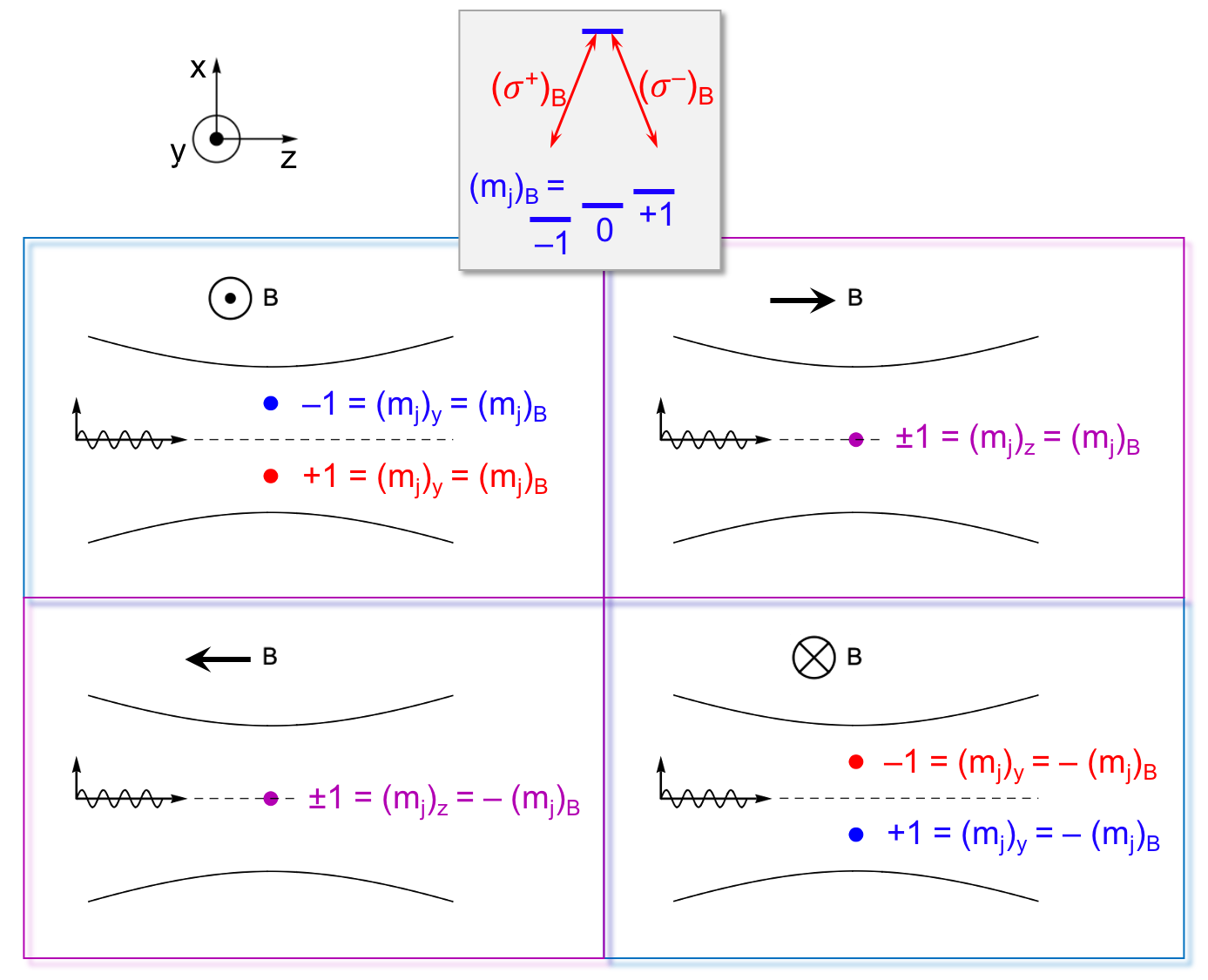
The off-axis trapping locations offer interesting opportunities to manipulate the motion of atoms in the tweezer, see Fig. 3. Let us imagine an atom trapped in the state. As we slowly rotate the magnetic field in the plane, the orientation of the atom will adiabatically follow the rotating quantization axis. After rotating the field , the spin will have maintained its orientation relative to , i.e. . However, its orientation will have flipped in space, , since has changed direction. The space-referenced spin flip implies that the atom must have moved to the other side of the optical axis. Thus, by rotating the magnetic field in the plane at a frequency , we effectively shake the trap back and forth: . The levels are shaken with opposite phase.
Shaking the trap at an amplitude is equivalent to a harmonic driving force , with the trap frequency. Resonant shaking, , will induce an oscillatory motion in the trap. For example, for a tweezer with a laser wavelength of m, a Gaussian waist of 2m, holding an atom of mass in a 20K deep trap, the trap frequency will be kHz. In a simple driven harmonic oscillator model only 3.5 drive cycles would impart enough energy to kick the atom out of the trap, corresponding to a velocity of cm/s. In reality one would of course need to take anharmonicity into account. The point here is that magnetic field modulation can easily induce oscillatory motion in the trap which can then be detected either as trap loss, or by using time-of-flight imaging methods. For the required magnetic field a few gauss should be sufficient, to ensure that the Larmor frequency is large compared to the trap frequency. Rotating the field at frequencies of kHz is well possible, being comparable to what is used in TOP traps Petrich et al. (1995).
Many available atomic level systems should be suitable to display off-axis tweezer trapping. For example, in 88Sr the transition would provide a transition. The outer state couples only to the polarization component, so its spatial shift will be . Using 87Rb one could operate a tweezer red detuned to the line (795 nm), driving the two hyperfine lines . Also in this case the outer state is displaced by , as long as the detuning stays small compared to the fine structure splitting of the lines.
In summary, it is predicted that a circular dipole can deflect a focused laser beam, similar to a spinning ball deflecting a stream of air in the Magnus effect. The reaction force on the atom leads to spin-dependent, off-axis displacement of atoms trapped in an optical tweezer. For a pure circular dipole the displacement is , independent of many trap parameters. An external magnetic field can be used to induce spin-dependent motion or to perform Stern-Gerlach type analysis of the spin states of the atom in the tweezer.
I would like to thank N.J. van Druten, R. Gerritsma, J. Minar, and A. Urech for stimulating and encouraging discussions as well as careful reading of the manuscript. This work was supported by the Netherlands Organization for Scientific Research (NWO).
References
- Magnus (1853) G. Magnus, Annalen der Physik 164, 1 (1853).
- Darwin (1932) C. G. Darwin, Proceedings of the Royal Society of London. Series A 136, 36 (1932).
- Araneda et al. (2019) G. Araneda, S. Walser, Y. Colombe, D. B. Higginbottom, J. Volz, R. Blatt, and A. Rauschenbeutel, Nature Physics 15, 17 (2019).
- Allen et al. (1992) L. Allen, M. W. Beijersbergen, R. J. C. Spreeuw, and J. P. Woerdman, Phys. Rev. A 45, 8185 (1992).
- Bliokh and Nori (2015) K. Y. Bliokh and F. Nori, Physics Reports 592, 1 (2015).
- van Enk and Nienhuis (1994) S. J. van Enk and G. Nienhuis, Journal of Modern Optics 41, 963 (1994).
- Dorn et al. (2003) R. Dorn, S. Quabis, and G. Leuchs, Journal of Modern Optics 50, 1917 (2003).
- Nieminen et al. (2008) T. A. Nieminen, A. B. Stilgoe, N. R. Heckenberg, and H. Rubinsztein-Dunlop, J. Opt. A: Pure Appl. Opt. 10, 115005 (2008).
- Monteiro et al. (2009) P. B. Monteiro, P. A. M. Neto, and H. M. Nussenzveig, Phys. Rev. A 79, 033830 (2009).
- Bliokh et al. (2010) K. Y. Bliokh, M. A. Alonso, E. A. Ostrovskaya, and A. Aiello, Phys. Rev. A 82, 063825 (2010).
- Rodríguez-Herrera et al. (2010) O. G. Rodríguez-Herrera, D. Lara, K. Y. Bliokh, E. A. Ostrovskaya, and C. Dainty, Phys. Rev. Lett. 104, 253601 (2010).
- Bliokh et al. (2011) K. Y. Bliokh, E. A. Ostrovskaya, M. A. Alonso, O. G. Rodríguez-Herrera, D. Lara, and C. Dainty, Opt. Express 19, 26132 (2011).
- Angelsky et al. (2012) O. V. Angelsky, A. Y. Bekshaev, P. P. Maksimyak, A. P. Maksimyak, S. G. Hanson, and C. Y. Zenkova, Opt. Express 20, 3563 (2012).
- Thompson et al. (2013) J. D. Thompson, T. G. Tiecke, A. S. Zibrov, V. Vuletić, and M. D. Lukin, Phys. Rev. Lett. 110, 133001 (2013).
- Barredo et al. (2016) D. Barredo, S. de Léséleuc, V. Lienhard, T. Lahaye, and A. Browaeys, Science 354, 1021 (2016).
- Endres et al. (2016) M. Endres, H. Bernien, A. Keesling, H. Levine, E. R. Anschuetz, A. Krajenbrink, C. Senko, V. Vuletić, M. Greiner, and M. D. Lukin, Science 354, 1024 (2016).
- Bernien et al. (2017) H. Bernien, S. Schwartz, A. Keesling, H. Levine, A. Omran, H. Pichler, S. Choi, A. S. Zibrov, M. Endres, M. Greiner, V. Vuletić, and M. D. Lukin, Nature 551, 579+ (2017).
- Cooper et al. (2018) A. Cooper, J. P. Covey, I. S. Madjarov, S. G. Porsev, M. S. Safronova, and M. Endres, Phys. Rev. X 8, 041055 (2018).
- Norcia et al. (2018) M. A. Norcia, A. W. Young, and A. M. Kaufman, Phys. Rev. X 8, 041054 (2018).
- Pagano et al. (2019) G. Pagano, F. Scazza, and M. Foss-Feig, Advanced Quantum Technologies 2, 1800067 (2019).
- Jackson et al. (2020) N. Jackson, R. Hanley, M. Hill, F. Leroux, C. Adams, and M. Jones, SciPost Physics 8, 038 (2020).
- Anderegg et al. (2019) L. Anderegg, L. W. Cheuk, Y. Bao, S. Burchesky, W. Ketterle, K.-K. Ni, and J. M. Doyle, Science 365, 1156 (2019).
- Saskin et al. (2019) S. Saskin, J. Wilson, B. Grinkemeyer, and J. Thompson, Phys. Rev. Lett. 122, 143002 (2019).
- Wang et al. (2020) K.-P. Wang, J. Zhuang, X.-D. He, R.-J. Guo, C. Sheng, P. Xu, M. Liu, J. Wang, and M.-S. Zhan, Chin. Phys. Lett. 37, 44209 (2020).
- Madjarov et al. (2019) I. S. Madjarov, A. Cooper, A. L. Shaw, J. P. Covey, V. Schkolnik, T. H. Yoon, J. R. Williams, and M. Endres, Phys. Rev. X 9, 041052 (2019).
- Norcia et al. (2019) M. A. Norcia, A. W. Young, W. J. Eckner, E. Oelker, J. Ye, and A. M. Kaufman, Science 366, 93 (2019).
- Note (1) See also Dooghin et al. (1992) for a very different kind of analogy of the Magnus effect.
- Schwartz and Dogariu (2006) C. Schwartz and A. Dogariu, Opt. Express 14, 8425 (2006).
- Arnoldus et al. (2008) H. F. Arnoldus, X. Li, and J. Shu, Opt. Lett. 33, 1446 (2008).
- Caldwell and Tarbutt (2020) L. Caldwell and M. R. Tarbutt, Phys. Rev. Research 2, 013251 (2020).
- Jackson (1999) J. D. Jackson, Classical Electrodynamics, 3rd ed. (Wiley, New York, NY, 1999) Ch. 9 and 10.
- Schlesser and Weis (1992) R. Schlesser and A. Weis, Opt. Lett. 17, 1015 (1992).
- Mandel and Wolf (1995) L. Mandel and E. Wolf, Optical Coherence and Quantum Optics (Cambridge University Press, 1995) Ch. 3 and 5.
- (34) See Supplemental Material for further details.
- Richards and Wolf (1959) B. Richards and E. Wolf, Proceedings of the Royal Society of London. Series A. Mathematical and Physical Sciences 253, 358 (1959).
- Gordon and Ashkin (1980) J. P. Gordon and A. Ashkin, Physical Review A 21, 1606 (1980).
- Pellegrino et al. (2014) J. Pellegrino, R. Bourgain, S. Jennewein, Y. R. P. Sortais, A. Browaeys, S. D. Jenkins, and J. Ruostekoski, Phys. Rev. Lett. 113, 133602 (2014).
- Machluf et al. (2019) S. Machluf, J. B. Naber, M. L. Soudijn, J. Ruostekoski, and R. J. C. Spreeuw, Phys. Rev. A 100, 051801 (2019).
- Moritz et al. (2003) H. Moritz, T. Stöferle, M. Köhl, and T. Esslinger, Phys. Rev. Lett. 91, 250402 (2003).
- Paredes et al. (2004) B. Paredes, A. Widera, V. Murg, O. Mandel, S. Fölling, I. Cirac, G. V. Shlyapnikov, T. W. Hänsch, and I. Bloch, Nature 429, 277 (2004).
- Kinoshita et al. (2004) T. Kinoshita, T. Wenger, and D. S. Weiss, Science 305, 1125 (2004).
- Jacqmin et al. (2011) T. Jacqmin, J. Armijo, T. Berrada, K. V. Kheruntsyan, and I. Bouchoule, Phys. Rev. Lett. 106, 230405 (2011).
- Stellmer et al. (2011) S. Stellmer, R. Grimm, and F. Schreck, Phys. Rev. A 84, 043611 (2011).
- Petrich et al. (1995) W. Petrich, M. H. Anderson, J. R. Ensher, and E. A. Cornell, Phys. Rev. Lett. 74, 3352 (1995).
- Dooghin et al. (1992) A. V. Dooghin, N. D. Kundikova, V. S. Liberman, and B. Y. Zel’dovich, Phys. Rev. A 45, 8204 (1992).
Supplemental Materials for:
Off-axis optical tweezers by an optical analog of the Magnus effect
Robert J.C. Spreeuw
Van der Waals-Zeeman Institute, Institute of Physics, University of Amsterdam,
PO Box 94485, 1090 GL Amsterdam, The Netherlands
I Spatial vs. angular -space coordinates
In this paper we express all fields by their angular spectrum . This is usually defined for fields propagating out into a half space (see Ch. 3.2 in Mandel and Wolf (1995)), as is clearly the case for the incident beams. The relationship with the field in the plane is given by
| (S1) |
with the laser wave vector. For the Gaussian beam with angular waist the above equation yields the familiar Gaussian beam cross section, with minimum waist , see also Ch. 5 in Mandel and Wolf (1995). The angular tophat beam approximates the output of a uniformly illuminated circular lens, and Eq. (S1) yields the resulting Airy pattern in the focal plane .
Although the emission by a dipole is not confined to , the angular representation of the radiation pattern of a dipole in a direction is well known to be given by Eq. (10) (main text), see for example Ch. 9 in Jackson (1999). Only the radiating, or ‘far field’, terms () are relevant in our case, because one can evaluate the beam deflection at arbitrarily large distance of the dipole, where the near fields () have become negligible.
In the plane () of a dipole,
| (S2) |
shows the spiral wave character in the prefactor .
The factor in Eq. (10) (main text) is a crucial detail. It is a consequence of expressing the spherical waves of the dipole field as an angular spectrum of plane waves. The same factor can be recognized in the Weyl representation of a diverging spherical wave Mandel and Wolf (1995). In the case at hand, one can readily see that it also ensures that a resonant beam is attenuated (absorbed) in the forward direction, due to destructive interference of incident and scattered waves.
The phase factor in Eq. (10) (main text) follows from the steady state of the optical Bloch equations Cohen-Tannoudji et al. (1998). In a two-level atom with states , the induced dipole moment is given by the off-diagonal density matrix element . If the atom is driven at detuning by a monochromatic field with (real) amplitude the steady state (for ) is given by
| (S3) |
which has a complex argument given by . Here, since we choose an polarized incident wave, is the phase of the component of the dipole, relative to the incident field.
II Low saturation limit
In the definition of the saturation parameter we include the detuning, following Cohen-Tannoudji et al. (1998),
| (S4) |
with the intensity and the saturation intensity. In the low-saturation limit, characterized by , the scattered light is almost entirely coherent, with a small incoherent fraction equal to . In optical tweezer experiments, using far off-resonant laser beams, typical values for are in the range , so that is indeed well fulfilled and the incoherent scattering rate is low.
III Field amplitudes
The peak amplitudes are related to the total power in the incident beam by
| (S5) |
for the Gaussian and angular tophat beam, respectively. The integrals were performed using Mathematica software Mat . For the Gaussian, the equality is only approximate, we give here the leading term of a power series in . The above expressions have been written as a product of the forward () radiant intensity and an effective solid angle.
The average wave vector of the incident beams is shorter than the corresponding value for a plane wave,
| (S6) |
The amplitude ratios and can be obtained from the energy conservation condition
| (S7) |
The scattering term would increase the outflowing power, which must be cancelled by the interference term . As a result,
| (S8) | |||||
| (S9) |
where in the Gaussian case the leading order in is given.
With these ratios the interference terms in the radiant intensity, Eq. (5) (main text) can be obtained as
| (S10) |
with
| (S11) |
For the deflection, expressed as we evaluate the integral of Eq. (7) (main text) to obtain
| (S12) |
for the Gaussian beam, and
| (S13) |
for the angular tophat beam.
Note that in both cases the component is absent. To leading order, the deflection angle is just given by
| (S14) |
which leads to Eq. (14) of the main text.
IV Calculation for a displaced atom
When the atom is located at a position away from the origin, the angular components of the scattered wave are phase shifted by an amount , so that the interference term, Eq. (5) (main text), is modified to
| (S15) |
For a displacement along , we have so that
| (S16) |
In the integrals and , we develop the integrand in a power series of , up to fourth order and integrate the terms separately.
For the amplitude ratios and we find that their lowest order ( and ) is not affected by . For the deflection angle the leading order in is still fourth order, and up to order the angle is
| (S17) |
for a dipole, respectively. This shows that the deflection angle, and thus also the transverse force, vanishes if the atom is displaced by an amount .
References
- Mandel and Wolf (1995) L. Mandel and E. Wolf, Optical Coherence and Quantum Optics (Cambridge University Press, 1995) Ch. 3 and 5.
- Jackson (1999) J. D. Jackson, Classical Electrodynamics, 3rd ed. (Wiley, New York, NY, 1999) Ch. 9 and 10.
- Cohen-Tannoudji et al. (1998) C. Cohen-Tannoudji, J. Dupont-Roc, and G. Grynberg, Atom-Photon Interactions: Basic Process and Applications (Wiley-VCH, New York, 1998).
- (4) Wolfram Research, Inc., Mathematica, Version 12.0, Champaign, IL (2020).