Heartbeat-Based Synchronization Scheme for the Human Intranet: Modeling and Analysis
Abstract
Sharing a common clock signal among the nodes is crucial for communication in synchronized networks.
This work presents a heartbeat-based synchronization scheme for body-worn nodes. The principles of this coordination technique combined with a puncture-based communication method are introduced. Theoretical models of the hardware blocks are presented, outlining the impact of their specifications on the system. Moreover, we evaluate the synchronization efficiency in simulation and compare with a duty-cycled receiver topology. Improvement in power consumption of at least 26% and tight latency control are highlighted at no cost on the channel availability.
Keywords:
Body Area Network (BAN); Synchronization; Heartbeat; Duty-cycled receiver.I Introduction
The Human Intranet, introduced in [1], is a human body-dedicated network. As part of Wireless Body Area Network (WBAN), it ensures interactions between all kind of sensors (e.g. temperature, pressure, displacement…) and actuators (e.g. smart prosthetic, insulin pump…), as well as interfacing the human body (e.g. brain-machine interfaces) [2].
Positioned as a platform augmenting human capabilities, including life support applications, the Human Intranet must operate faultlessly. It relies on a robust architecture, capable of mitigating different network topologies [3] enabling high throughput and low latency [4], [5], while being power efficient.
The existing IEEE 802.15.6 standard [6] that cover such a network is good in terms communication reliability and security but has blocking limitations in its implementation: 1- or 2-hop network topology and heavy synchronization requirements limit its flexibility and significantly impact its efficiency.
This paper introduces a new synchronization scheme based on the heartbeat to overcome those limitations. Highlighting promising results in [7], a heartbeat-based synchronization scheme is proposed as a combination of puncture-based communication and dedicated hardware. Section II details the synchronization principle. Section III presents the models. The simulation results are provided in Section IV along with a comparison with a duty-cycled architecture. Finally, Section V concludes this paper.
II Heartbeat-Based Synchronization Principle
II-A Human Intranet architecture
The Human Intranet is meant to interconnect a wide range of wearable devices. They can be split into two categories: hubs and leaves (see Fig. 1LABEL:sub@fig_HI_Network), based on their purpose (sensor or actuators), computing capabilities or access to energy [8].
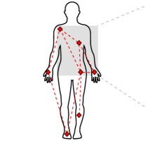
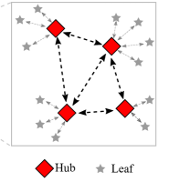
The data traffic flows through the network as follows: The main traffic takes place between hubs in a bi-directional manner with the highest data rate achievable. It is the default situation. Each hub can exchange data with all the reachable hubs in its vicinity since no particular network topology is preferred (star, mesh or a combination of both). The leaves however, only communicate with one hub as shown in Fig. 1LABEL:sub@fig_Network_Archi. The amount of data generated by a leaf is limited.
Given the above architecture, a high level communication scheme is imagined where the leaves “puncture” the established communication between main nodes, to upload data to their respective hubs. This approach allows the system to take full advantage of the channel bandwidth available, enabling high data rate with simple communication scheme, offering a better energy efficiency [9].
II-B Proposed synchronization scheme
The challenge of such a communication protocol lies in the nodes synchronization efficiency. The adequate coordination scheme optimizes three major parameters: the channel availability, the system power consumption and its latency. The channel availability, expressed as a percentage, is defined as the ratio between the hub-to-hub communication duration over the total considered communication period. Since the objective is to optimize the entire system, the power consumption calculation takes into account all nodes included in the analysis (i.e. at least a transmitter and a receiver). The latency represents the time elapsed from data availability to its transmission.
The heartbeat-based synchronization requires all nodes to detect the heartbeat and use it as a time reference. A “superframe” is defined as the elapsed time between two heartbeats. Within this time frame, the communication between leaves and hubs is scheduled and periodically triggered. The synchronization scheme is depicted in Fig. 2.
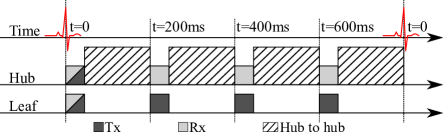
A listening window is opened by the leaves once, at the beginning of each superframe. It provides a bi-directional communication capability allowing schedule update for instance.
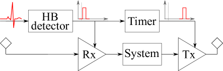
Fig. 3 presents the heartbeat-based synchronization block-diagram. The heartbeat detector (HB detector) translates the ECG signal into a digital output, resetting the timer. In parallel, the receiver is switched ON for a short period of time. The timer generates periodic ticks, triggering a transmission based on its counter auto-reload value. This scheme is repeated continuously until the next heartbeat. This study does not consider the set-up phase: the nodes schedule is already established.
Many channel access methods [10] (e.g. TDMA) and synchronization implementations (e.g. RTC) already exist. However, exploiting the heartbeat as a synchronization signal has been rarely considered. To the author’s knowledge the only previous related work is [7]. It offers unique advantages such as being available from the subject at no extra energy and transmission cost, and adapting automatically to the wearer’s physical activity. The heartbeat can be detected by various sensing modalities: electric, light, sound and pressure for instance.
III Hardware Architecture and Modeling
This section details the functional blocks models ensuring the synchronization.
III-A Heartbeat Detector
The heartbeat detector identifies the peak (i.e. “R”) within the QRS complex [11], not its shape. It translates the ECG signal into a digital output as implemented in [12]. The heartbeat detector power consumption is noted as .
The main source of inaccuracy is the signal propagation delay between two nodes. From [13], the signal propagation speed is larger than m/s. Called “heartbeat skew”, the propagation delay is only a function of the distance d between the nodes: s.
III-B Timer
The timer, embedding an oscillator and a counter, divides the superframe into sub-frames. It generates a signal when the elapsed time from the last heartbeat or timeout is equal to its internal setting. The timer is reset on each heartbeat, limiting inaccuracy accumulation over the running duration. Its power consumption is noted as .
In terms of inaccuracy, three sources are identified: the oscillator frequency offset, the frequency drift and the accumulated random jitter.
III-B1 Offset frequency
It specifies the deviation from the ideal frequency of oscillation. It is compensated by performing a one-time calibration, adjusting the counter auto-reload value. The offset frequency translates into a time uncertainty, , which eventually equals a single oscillator period.
III-B2 Frequency drift
It expresses the oscillation frequency variation due to close-in phase noise [14]. It is deterministic and bounded. It is calculated here as a ratio in ppm, , of the theoretical frequency of oscillation. The resulting inaccuracy, , is given in (1).
| (1) |
III-B3 Accumulated random jitter
It follows a Gaussian normal distribution. Its mean value is null since the drift is considered as a distinct parameter.
Given the application (i.e. a timer), it is more relevant to analyze the accumulated random jitter over time. All cycles are independent, and the accumulated random jitter also follows a Gaussian normal distribution [15], [16], which variance only depends on the number of oscillations : , where is the jitter variance for one oscillation period.
The inaccuracy due to the random jitter in (2) considers a window as large as , guaranteeing a covering probability higher than 99.993%.
| (2) |
III-C Transmitter and Receiver
In this study, the transmitter and receiver models are limited to their power consumption (no set-up time considered). The transmitter power consumption is a function of the link data rate times the Tx energy efficiency . The receiver energy consumption depends on the listening windows duration and the receiver power consumption .
III-D Metrics
The synchronization scheme efficiency is evaluated by the three metrics introduced in Section II: channel availability, system power consumption and latency. Their analysis is conducted under two circumstances: the ideal and realistic case. The former does not take into account the loss while the latter includes the system nonidealities in terms of timing.
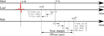
In order to compensate for the timing inaccuracy within each node, the synchronization window must be properly chosen to ensure the communication. As depicted in Fig. 4, a worst-case approach is followed. Maximum values of inaccuracy are considered with opposite consequences on Tx and Rx. The synchronization margin taken per puncturing event is calculated in (3).
| (3) |
The synchronization margin increases over time. The total margin taken for a node over the superframe duration is calculated in (4). It depends on the number of puncturing events for the given node.
| (4) |
In case Rx is late compared to Tx (opposite of Fig. 4), the total wait time, , becomes twice the synchronization margin expressed in (3).
III-D1 Channel availability
Under the ideal case, the total transmission time per superframe period (), equals the reception time. The ideal channel availability is calculated in (5) for leaves connected to a hub.
| (5) |
The realistic channel availability (6), equals to degraded by the total wait time per node.
| (6) |
III-D2 System power consumption
Noted in the ideal case, it considers leaves and one hub (7).
| (7) |
The realistic system power consumption, , increases as a function of the additional time spent waiting for data from the leaves. Its expression is given in (8).
| (8) |
III-D3 Latency
Given the synchronization mechanism and margin taken on each puncturing events, the latency does not suffer additional coordination time.
IV Simulation Results
IV-A Heartbeat-based synchronization scheme
In order to provide clear simulation results, hypotheses are made, or numerical values are chosen issued from existing implementations. This study also aims to define the system requirements and their impact on the synchronization efficiency. Conservative values are considered.
In our Human Intranet scenario, the leaf-hub distance is not longer than 15 cm (about 50 cm between hubs) leading to s.
The system parameters introduced above and needed for the synchronization analysis are listed in Table I.
| Description | Symbol | Value | Unit |
|---|---|---|---|
| Oscillator jitter variance | 1 | s | |
| Oscillator drift | 500 | ppm | |
| Heart beat detector power consumption | 100 | nW | |
| Timer power consumption [17] | 100 | nW | |
| Tx energy efficiency | 100 | nJ/b | |
| Rx energy efficiency | 100 | nJ/b | |
| Communication data rate | 100 | kb/s | |
| Data generation rate (from leaf) | 1 | kb/s | |
| Wake-up beacon length | 16 | b |
The oscillator frequency is selected kHz. It is an optimal trade-off between timing granularity (i.e. ) and drift over time, respectively dominating the inaccuracy at low and high frequencies. The overall timing inaccuracy and its components are plotted in Fig. 5 for ms (inter-heartbeat duration at 75 beats per minute (bpm)).
Following (6) and (8), the channel availability and system power consumption are computed and plotted in Fig. 6, in a 2-node configuration for two latency values: 50 ms and 200 ms.
The impact of latency on channel availability illustrated in Fig. 6LABEL:sub@fig_HB_sync_CA, is inversely proportional to the duration between two consecutive uploads. At ms, drops from 97% to 92% for latencies of 200 ms and 50 ms respectively. This observation is also applicable to , since the additional term converting (7) into (8) is the same. For the given operating point, the consumption is more than doubled.
IV-B Comparison with duty-cycled receivers
Receiver duty-cycling is one of the best recognized method for lowering a communication system power consumption [[18]]. This method will be used as a comparison base. The duty-cycled system timing is described in [18]. Unlike the heartbeat-based solution, the nodes are not synchronized. The leaves randomly wake up, listening for a wake-up beacon from the hub. If a full wake-up message is detected, the transmission is initiated. They otherwise go back to sleep mode. The leaves listening windows last two wake-up beacons and one inter-wake-up beacon slots.
The performance of such a synchronization scheme is plotted in Fig. 7 as a function of the duty-cycle ratio. The channel availability, system power consumption and latency are computed with the parameters from Table I. It is worth noting that the duty-cycle scheme relies on probabilities. To highlight this particularity, Fig. 7 includes error bars, specifying the possible range of results around their mean.
The duty-cycled architecture has an optimal power consumption for duty-cycles lower than 10%, illustrated in Fig. 7LABEL:sub@fig_DuCy_sync_CA_Psys. However, this minimum power consumption is higher than the heartbeat-based counterpart. Additionally, at this functioning point, the channel availability stays lower than the heartbeat-based equivalent.
The duty-cycle approach offers a better average channel availability for duty-cycle ratios higher than 10%, for both latency requirements.
The heartbeat-based scheme allows at least a 26% and a 40% power consumption saving while uploading data every 50 ms and 200 ms respectively, in a worst-to-best comparison (max of Fig. 6LABEL:sub@fig_HB_sync_Psys, min of Fig. 7LABEL:sub@fig_DuCy_sync_CA_Psys).
The last evaluation metric is the synchronization latency. Instantaneous in the heartbeat-based configuration due to a properly estimated listening window, the duty-cycled topology requires an additional synchronization time once the data is ready. Limited for duty-cycle ratios larger than 10%, it is bounded but totally unpredictable otherwise (see Fig. 7LABEL:sub@fig_Xtra_lat). This becomes problematic for demanding applications. It depends on the wake-up beacon length and increases exponentially for low duty-cycle ratios.
The heartbeat-based synchronization scheme presents a more homogeneous (optimized combination of all three metrics) mean to initiate a communication between two nodes located on the body. It is a power efficient solution, optimizing the channel availability while offering tight control on the system latency, a crucial capability for critical applications.
V Conclusion
A new synchronization scheme based on the heartbeat is introduced. It is composed of a timer, reset on each heartbeat, dividing the inter-heartbeat window (superframe) into sub-frames. This approach enables scheduled communication, optimizing the channel occupation and power consumption while offering a tight control on latency. A mathematical model, taking into account the hardware nonidealities is presented. It outlines the relationship between the hardware requirements and their impacts on the synchronization performance. Efficiency of the overall scheme is evaluated in a side-by-side comparison with a common duty-cycled receiver architecture. The heartbeat-based synchronization scheme provides more stable channel availability, a power consumption improved by at least 26% without suffering latency uncertainty. In addition, all three parameters can be optimized together without suffering major trade-offs. The heartbeat-based synchronization scheme is a promising solution for an efficient Human Intranet implementation.
References
- [1] J. M. Rabaey, “The human intranet–where swarms and humans meet,” IEEE Pervasive Computing, vol. 14, no. 1, pp. 78–83, 2015.
- [2] J. M. Rabaey, “Brain-machine interfaces—the core of the human intranet,” in 2015 6th International Workshop on Advances in Sensors and Interfaces (IWASI). IEEE, 2015, pp. 113–114.
- [3] A. Moin, P. Nuzzo, A. L. Sangiovanni-Vincentelli, and J. M. Rabaey, “Optimized design of a human intranet network,” in Proceedings of the 54th Annual Design Automation Conference 2017. ACM, 2017, p. 30.
- [4] K. Englehart, B. Hudgins et al., “A robust, real-time control scheme for multifunction myoelectric control,” IEEE transactions on biomedical engineering, vol. 50, no. 7, pp. 848–854, 2003.
- [5] L. H. Smith, L. J. Hargrove, B. A. Lock, and T. A. Kuiken, “Determining the optimal window length for pattern recognition-based myoelectric control: balancing the competing effects of classification error and controller delay,” IEEE Transactions on Neural Systems and Rehabilitation Engineering, vol. 19, no. 2, pp. 186–192, 2010.
- [6] IEEE, “IEEE 802.15: WPAN task group 6 (TG6) body area networks,” 2008.
- [7] H. Li and J. Tan, “Heartbeat-driven medium-access control for body sensor networks,” IEEE transactions on information technology in biomedicine, vol. 14, no. 1, pp. 44–51, 2009.
- [8] S. Movassaghi, M. Abolhasan, J. Lipman, D. Smith, and A. Jamalipour, “Wireless body area networks: A survey,” IEEE Communications surveys & tutorials, vol. 16, no. 3, pp. 1658–1686, 2014.
- [9] M. Abo-Zahhad, M. Farrag, and A. Ali, “Modeling and minimization of energy consumption in wireless sensor networks,” in 2015 IEEE International Conference on Electronics, Circuits, and Systems (ICECS). IEEE, 2015, pp. 697–700.
- [10] Multiple-Access Techniques. John Wiley & Sons, Ltd, 2003, ch. 8, pp. 275–320.
- [11] R. Zeng, Graphics-sequenced interpretation of ECG. Springer Singapore, 2015.
- [12] D. Da He and C. G. Sodini, “A 58 nW ECG ASIC with motion-tolerant heartbeat timing extraction for wearable cardiovascular monitoring,” IEEE transactions on biomedical circuits and systems, vol. 9, no. 3, pp. 370–376, 2014.
- [13] T. Buchner and J. Gierałtowski, “How fast does the ECG signal propagate within the body,” 03 2015.
- [14] N. Da Dalt and A. Sheikholeslami, Understanding Jitter and Phase Noise: A Circuits and Systems Perspective. Cambridge University Press, 2018.
- [15] M. Zielinski, M. Kowalski, D. Chaberski, and S. Grzelak, “Estimation of the clock signal jitter using the time-interval measurement system,” in Proc. of XVIII IMEKO World Congress Metrology for a Sustainable Development. Citeseer, 2006.
- [16] M. Zieliński, M. Kowalski, R. Frankowski, D. Chaberski, S. Grzelak, and L. Wydźgowski, “Accumulated jitter measurement of standard clock oscillators,” Metrology and Measurement Systems, vol. 16, no. 2, pp. 259–266, 2009.
- [17] S. Jeong, I. Lee, D. Blaauw, and D. Sylvester, “A 5.8 nW CMOS wake-up timer for ultra-low-power wireless applications,” IEEE Journal of Solid-State Circuits, vol. 50, no. 8, pp. 1754–1763, 2015.
- [18] N. S. Mazloum and O. Edfors, “Influence of duty-cycled wake-up receiver characteristics on energy consumption in single-hop networks,” IEEE Transactions on Wireless Communications, vol. 16, no. 6, pp. 3870–3884, 2017.