Terahertz emission from submicron solid targets irradiated by ultraintense femtosecond laser pulses
Abstract
Using high-resolution, two-dimensional particle-in-cell simulations, we investigate numerically the mechanisms of terahertz (THz) emissions in submicron-thick carbon solid foils driven by ultraintense (), ultrashort () laser pulses at normal incidence. The considered range of target thicknesses extends down to the relativistic transparency regime that is known to optimize ion acceleration by femtosecond laser pulses. By disentangling the fields emitted by longitudinal and transverse currents, our analysis reveals that, within the first picosecond after the interaction, THz emission occurs in bursts as a result of coherent transition radiation by the recirculating hot electrons and antenna-type emission by the shielding electron currents traveling along the fast-expanding target surfaces.
I Introduction
Terahertz (THz) waves, lying in between microwaves and optical waves, are of growing interest in various areas of research and industry covering medical imaging, remote detection, time-resolved molecular spectroscopy, cryptography, telecommunications, cultural heritage or environment Tonouchi (2007); Bergé et al. (2019). Nowadays, the operational bandwidth of THz sources is not restricted to the “THz gap”, but is routinely extended up to mid-infrared frequencies. Recently, novel challenges such as the development of compact THz electron accelerators Nanni et al. (2015); Sharma et al. (2018); Curcio et al. (2018) or THz-triggered chemistry LaRue et al. (2015) raised the need of mJ energy THz pulses with field strength at the level. As of now, optical rectification Vicario, Monoszlai, and Hauri (2014) or the tilted-pulse-front technique Fülöp et al. (2014) in nonlinear crystals can achieve sub-mJ THz energies with a few field strengths, yet further progress in these solid-based technologies is hampered by their inherent damage threshold. By contrast, plasma spots created by intense laser pulses may supply suitable damage-free emitters Hafez et al. (2016). Such is the case with gases ionized by two-color laser pulses (e.g., fundamental and second harmonics) of moderate intensities , which, through the generation of photocurrents, have been shown to radiate ultrabroadband (), relatively strong ( GV/m) terahertz pulses Kim et al. (2008). Using a pump laser wavelength, this mechanim lately resulted in THz pulses, associated with laser-to-THz conversion efficiency Nguyen et al. (2018); Jang et al. (2019); Koulouklidis et al. (2020). However, when applied to standard laser wavelengths, it seems to be limited to the production of energy THz pulses only Oh et al. (2013).
Higher THz energy yields, approaching the mJ level, may be attained in relativistic gas-jet interactions Déchard et al. (2018); *Dechard:prl:2019 through coherent transition radiation (CTR) by wakefield-accelerated electrons Leemans et al. (2003); *Schroeder:pre:2004. This radiation is coherent in the THz frequency domain as the corresponding wavelengths exceed the typical dimensions of the fast electron source; its power therefore scales quadratically with the number of fast electrons exiting the plasma. The promising potential of this wakefield accelerator-based setup, particularly in the matched-blowout regime as predicted by particle-in-cell (PIC) numerical simulations Déchard et al. (2018); *Dechard:prl:2019, still awaits experimental demonstration. On the other hand, the capability of relativistic laser-solid interactions to give rise to few THz pulses has already been evidenced Liao et al. (2019). The available data suggest that THz emission then proceeds through a variety of mechanisms, all triggered by the motion of laser-driven high-energy electrons.
When an intense laser pulse impinges onto a solid target, the latter is rapidly ionized and a population of energetic electrons is generated via various processes (e.g., heating Kruer and Estabrook (1985); Debayle et al. (2013), vacuum heating Brunel (1987); Bauer and Mulser (2007); May et al. (2011) or resonant absorption Forslund et al. (1975); Xu et al. (2006)), depending on the laser intensity, incidence angle and density scale length Kemp et al. (2014). The dynamics of those hot electrons, together with the collective response of the target bulk electrons and ions, can initiate a number of radiative processes in the THz frequency domain. This is so because, as discussed below, their characteristic time scales are determined by either the laser duration, the light transit time through the target, or the ion acceleration time, all ranging from a few to .
Let us now consider the case of steep-gradient, micron-thick targets, irradiated at normal incidence by a relativistically intense () short-pulse laser. Firstly, the crossing of the target surfaces by the longitudinally accelerated fast electrons generates CTR over broad frequencies Zheng et al. (2003); Schroeder et al. (2004); Bellei et al. (2012). Unlike gases where CTR is highly collimated on axis due to ultrarelativistic, low-divergence fast electrons Déchard et al. (2018), CTR from solid-targets seems to be emitted at broader angles as a result of less energetic and more divergent electrons Ding and Sheng (2016). This radiation is accompanied by an outward transverse current pulse that travels close to the speed of light along the target surface, and acts to screen the fields inside the plasma Tokita et al. (2015). This transient surface current radiates like the charge image of the energetic electron bunch, and is an intrinsic feature of transition radiation Ginzburg (1982).
Now, very few electrons are able to escape the potential barrier set up around the positively charged target, most of them being drawn back into the target Myatt et al. (2007); Poyé et al. (2015). If the target is thicker than the longitudinal extent of the recirculating hot electrons, yet much shorter than their (millimeter-range) deceleration length, their back and forth motion across the target induces periodic CTR bursts Ding and Sheng (2016). When exiting the target, those electrons can propagate a distance of the order of their Debye length () before being reflected. There ensue hot-electron sheaths at the target surfaces, which expand radially at a velocity due to some electrons accelerated by the laser at large angles from the target normal or deflected by self-generated fields. Note that, at oblique laser incidence, the sheath formed at the irradiated side may comprise hot electrons flowing along the target surface due to counteracting self-induced electric and magnetic fields Nakamura et al. (2004). THz emissions can also take place during the emergence phase of those sheaths.
The quasistatic fields generated by the outward-moving hot-electron sheaths make up another inductive source of shielding surface currents. In PIC simulations of laser-solid interactions, owing to the relatively small () target sizes generally considered, the above two types of surface current pulses, which respond, respectively, to the CTR by the hot electrons crossing the target boundaries and the static fields due to the laterally moving hot electrons, are difficult to disentangle because of their relativistic velocities. In the following, we will refer to them under the generic term of “shielding (surface) currents”. Whereas they do not radiate while flowing steadily along the target surfaces, they can emit further radiation when reaching the transverse target edges Zhuo et al. (2017) in an antenna-like fashion Smith (2001).
The electrostatic fields associated with the hot-electron sheaths eventually set into motion the target ions. The protons present in the target bulk or as surface contaminants respond the fastest given their large charge-to-mass ratio. This is the well-known target normal sheath acceleration (TNSA) mechanism, known to dominate ion acceleration in micrometric foils driven at laser intensities Wagner et al. (2016). This results in the outward expansion of a quasineutral electron-proton plasma, preceded, at its front, by a negatively charged double layer Mora (2003); *Mora:pre:2005. The relatively long-time-scale acceleration of the latter is the source of a wide-angle dipole-like radiation – often termed sheath radiation (SR) Gopal et al. (2012); *Gopal:prl:2013; *Gopal:ol:2013 –, scaling quadratically with the net charge of the double layer.
A record-high THz yield, corresponding to a laser-to-THz energy conversion efficiency, was achieved by Jin et al. (Jin et al., 2016), using a intensity, duration laser pulse and Cu foils with thicknesses . The energy of the THz radiation, peaking at about from the target rear normal, was found to scale as , consistent with the prediction of a simple SR model. An interesting feature was the development of multiple THz pulses over ps time scales, the number of which increasing in thinner targets. Lately, under similar conditions, Herzer et al. Herzer et al. (2018) managed to discriminate between the CTR and SR contributions. The latter was observed to yield a broader dipole-like angular distribution than the former, but with a much larger energy yield ( vs. ). In contrast to Ref. [Jin et al., 2016], the THz waveform then exhibited a single-cycle shape of duration.
Past simulation studies on THz emissions from laser-solid interactions have only considered micrometer-range target thicknesses. Such targets, however, may not be the most effective neither in terms of laser-to-hot-electron coupling nor of ion acceleration. The purpose of this paper is, rather, to investigate THz radiation from submicron foils irradiated by ultraintense femtosecond laser pulses, including nanometric targets enabling relativistic self-induced transparency (RSIT) of the laser pulse Vshivkov et al. (1998). The threshold conditions for this regime have been shown to entail a strong coupling efficiency into hot electrons and to enhance ion acceleration d’Humières et al. (2005); Esirkepov, Yamagiwa, and Tajima (2006); Brantov et al. (2015); Ferri et al. (2020). The optimal target thickness for ion acceleration, also corresponding to the onset of RSIT, is given by Esirkepov, Yamagiwa, and Tajima (2006); Brantov et al. (2015)
| (1) |
where is the dimensionless laser field strength ( is the laser field strength, the laser frequency, the electron mass, the elementary charge and the speed of light in vacuum), the laser wavelength, the related critical density ( is the vacuum permittivity) and the target electron density. For fiducial parameters (, ), is typically of a few 10 nm.
Most previous works on THz radiation from laser-solid interactions considered obliquely incident laser pulses Gopal et al. (2012); Ding and Sheng (2016); Jin et al. (2016); Zhuo et al. (2017); Herzer et al. (2018), yet this setup complicates the hot-electron generation and subsequent dynamics, besides causing a natural asymmetry in the angular distribution of the THz radiation. This makes it more intricate to distinguish the various THz radiation processes at play, and their related electron current sources. Therefore, to simplify the analysis, the present study will only address the case of a normally impinging laser pulse.
This paper is structured as follows. The simulation parameters are detailed in Sec. II. In Sec. III are reported the main features of the laser-driven electron and ion dynamics for a reference 500-nm-thick CH2 target. The resulting THz radiation emitted within the first 100 fs is analyzed in Sec. IV, notably by discriminating between the longitudinal and transverse current sources, and by untangling the contributions of the hot-electron and shielding surface currents. Several radiation processes are identified and the variations of their properties with the target thickness over a time scale are addressed in Sec. V. Our results are summarized in Sec. VI.
II Simulation setup
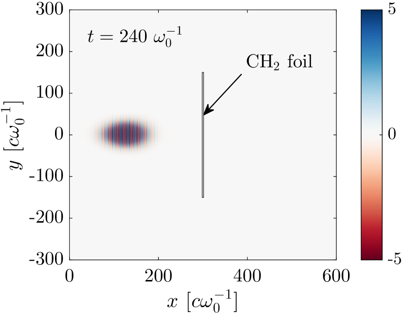
Our PIC simulations have been performed using the fully relativistic, electromagnetic code calder in 2D3V (2D in configuration space, 3D in momentum space) geometry. The laser pulse, of wavelength , is characterized by Gaussian spatial and temporal profiles of FWHM spot size and 30 fs FWHM duration, respectively. Its peak intensity is , corresponding to a dimensionless field strength . Propagating in the direction and linearly polarized along the axis, the laser pulse is focused at normal incidence onto fully ionized, sub-micron-thick CH2 foil targets with density. These comprise three charged particle species (electrons, C6+ and H+ ions). The initial total electron density is . The targets are initialized with sharp gradients, a transverse width and a thickness varying in the range . The minimum target thickness considered () is slightly above the predicted optimal thickness, . Simulations at lower thicknesses were not carried out due to excessive numerical cost.
The definition of the simulation mesh is a trade-off between having a domain large enough to allow propagation of the radiated fields over several 100 fs, and keeping the same spatio-temporal resolution and comparable data volume for all target sizes. The simulation domain has dimensions of . The grid size is (smaller than the target skin depth ) and the time step is . The grid size is only one third of the thinnest (15 nm) target, but its ultrafast laser-driven expansion will lead to an interaction effectively taking place over a broader, well resolved spatial region. Each particle species is initially represented by 400 macro-particles per cell at , and by 4000 macro-particles per cell at and in order to achieve comparable statistics in all cases. We did not investigate targets below the relativistic transparency threshold, because this would have forced us to reduce the spatial and time steps by the same factor, hence increasing prohibitively the computational time.
Figure 1 illustrates the simulation setup before the pulse hits the target. In this figure, and as in the following ones, space and time are normalized by and .
III Main features of the laser-foil interaction
Before examining the THz radiation processes, let us first describe the electron and ion dynamics induced by the intense laser pulse in the target.
Figure 2 shows four successive snapshots of the longitudinal () electron phase space along with the on-axis laser fields (). The target initially extends over the region , and the laser pulse reaches its maximum at . At [Fig. 2(a)], the laser’s rising edge has hit the target. The highly overcritical electron density causes strong laser reflection, and hence the formation of an electromagnetic standing wave in front of the target, with the and spatial extrema being separated by ( in units). The two standing-wave patterns are also dephased in time by (in units), which explains their nonequal instantaneous amplitudes.
Owing to their small mass, the electrons react the fastest to the laser field, and are energized through a combination of vacuum and skin layer heating processes Bauer and Mulser (2007); May et al. (2011); Debayle et al. (2013). A fraction of them are accelerated forward by the laser’s ponderomotive force in the form of -periodic jets, with maximum longitudinal momenta . As they flow into vacuum, a strong electrostatic sheath field () is induced which eventually reflects most of them back into the target and the (still present) laser wave (see the electrons at ). Upon interacting with the oscillating laser’s ponderomotive force and the resulting charge-separation field, the recirculating electrons develop an increasingly hot, symmetric -distribution inside the target, which favors further laser-driven energization Bauer and Mulser (2007); May et al. (2011). The energy spectrum of the forward-moving electrons is characterized by a decreasing exponential slope of (not shown). Some backward-moving electrons are energetic enough to overcome the ponderomotive potential and be injected into the standing wave [see Fig. 2(b) recorded at ]. These can be re-accelerated to even larger negative momenta () by the reflected part of the laser pulse, a process known as vacuum laser acceleration Yu et al. (2000); Thévenet et al. (2016) [see Fig. 2(c) recorded at ].
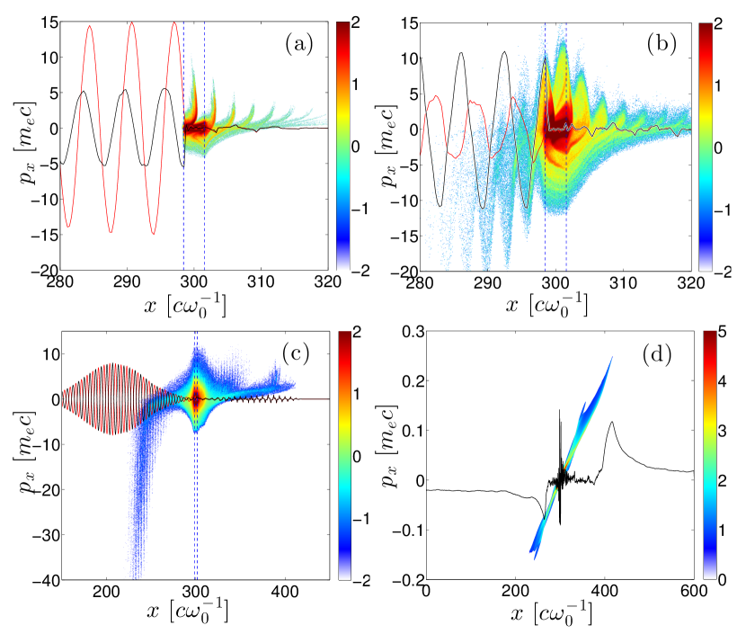
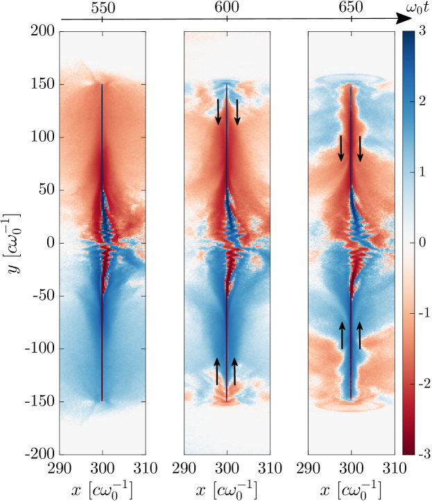
The electrostatic sheath field () set up by the motion of the laser-driven electrons leads to ion acceleration Mora (2003); *Mora:pre:2005; Brantov et al. (2015). The lighter protons rapidly separate from the carbon ions and reach the highest velocities. Figure 2(d) shows the proton longitudinal phase space as recorded at , overlaid with the longitudinal electrostatic field, averaged over a laser period. The forked shape of the phase space of protons originates from a combination of (prevailing) TNSA and radiation pressure acceleration. Some protons are also accelerated in the backward direction ) as a result of TNSA at the target frontside. The electrostatic field structures associated with forward and backward TNSA are clearly seen at and , respectively.
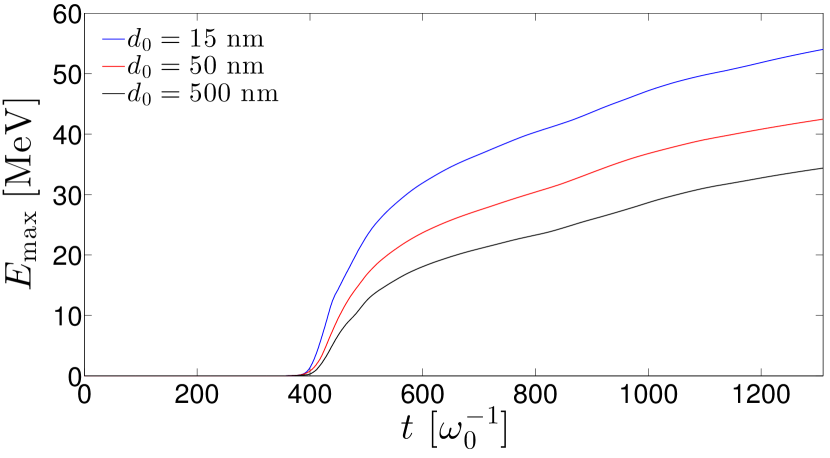
The black curve in Fig. 3 plots the temporal evolution of the instantaneous maximum energy, , of the forward-moving protons (). After a rapid growth at early times, increases more slowly by , yet without showing a clear saturation trend up to simulation time . This sustained acceleration is a consequence of the reduced 2D geometry because of improper description of the momentum anisotropy and transverse dilution of the hot electrons Liu et al. (2013); Stark et al. (2017). A faster drop in the sheath field strength is also expected in 3D once the ion front has travelled a distance comparable with the transverse size of the sheath, thus arresting ion acceleration at lower kinetic energies Brantov et al. (2015); Ferri et al. (2018).
The curves from simulations run with (red) and (blue) are also overlaid in Fig. 3. The expected enhancement of the proton acceleration efficiency with decreasing foil thickness (down to the RSIT threshold) is manifest: at , rises from at to 54 MeV at . Further inspection of the numerical data reveals comparable absorbed fractions of the laser energy in the three simulation cases (viz. from at to at ).
IV Analysis of the low-frequency radiation
IV.1 General picture of the THz field patterns
We now study the low-frequency (i.e., in the THz domain) fields generated from the laser-plasma interaction. Spatial distributions of these fields are obtained by Fourier transforming the original field distributions, applying a hypergaussian filter and then inverse Fourier transforming. We here take and a cut-off wavenumber associated with a frequency bandwidth .
An overview of their dynamics is provided by Figs. 4(a-i), which display the field distributions at three successive times following the laser interaction with the target. Although the field maps exhibit rather complex patterns, one can discern the following main structures:
-
Two outgoing radial waves originating from the laser spot and propagating in vacuum at the speed of light in the forward (1) and backward (1’) directions, respectively. Those waves are visible in the three field maps. Their mutual spatial offset indicates that the backward wave has been emitted about after the forward wave.
-
Two outgoing waves originating from the top (2) and bottom (2’) edges of the foil, also propagating at the speed of light. Those waves have been synchronously emitted after wave (1). The polarity of their field [Figs. 4(d-f)] indicates that they are associated with an accumulation of positive charges around the target edges.
-
The electrostatic sheath field (3) at the boundary of the expanding protons. This field, which is responsible for TNSA, is most pronounced in the forward direction (i.e., the preferential direction of the hot-electron flow at ) and is mainly -polarized. However, due to the transverse density gradient of the expanding proton cloud, it also comprises a component, which is an odd function of the transverse coordinate ().

IV.2 Identification of the radiating current sources
We now focus on the light-speed, low-frequency signals (1,1’) and (2,2’) revealed by the above snapshots of the distribution. Note that in the present 2D3V simulation of a -polarized laser pulse, the field captures the full magnetic component of the low-frequency radiation. This contrasts with the and components, which only carry a fraction of the radiated electric fields depending on their local polarization.
All radiated signals evidently result from the strong plasma currents generated by the laser-plasma interaction around the target. In particular, from previous works Ding and Sheng (2016); Liao et al. (2016); Herzer et al. (2018), we expect the strong longitudinal currents carried by the hot electrons breaking off the target back (resp. front) side to emit coherent transition radiation in the forward (resp. backward) direction. The transverse currents associated with the laterally moving hot electrons and the shielding plasma electrons should also contribute to the overall radiation. It is therefore worthwhile to identify whether the observed radiated signals mostly result from the longitudinal () or transverse () component of the laser-driven plasma currents.
To this purpose, we have added two Maxwell solvers in our code to advance separately the fields resulting from and . Specifically, the -driven fields and -driven fields are solved from the Maxwell-Faraday and Maxwell-Ampère equations:
| (2) | ||||
| (3) | ||||
| (4) | ||||
| (5) | ||||
| (6) | ||||
| (7) |
The resulting fields are then filtered as explained above.
IV.2.1 Longitudinal electron dynamics
Figures 5(a-i) present the results of this procedure at three different instants (i.e., , and ). The first row shows , the second one and the third one the total filtered field . Note that Figs. 5(h-i) reproduce Figs. 4(h-i) to help the reader connect the radiation patterns discussed in the following to the main low-frequency structures presented in the previous subsection.
Figures 5(a-c) demonstrate that, as expected, the two radial waves (1) and (1’) outgoing from both target sides are induced by . We ascribe these waves to CTR by the longitudinal hot-electron motion across the target surfaces. Accordingly, their polarity fulfills , with the hot-electron current source at the target center . Their relative delay corresponds to the reflection time of the initially forward-moving hot electrons by the sheath field set up at the target boundaries [see in Figs. 4(a-c)]. When viewed along a fixed direction from the target center, the two waves take on the form of half-cycle pulses with similar field strength as a function of the distance from the laser spot. At (i.e., after the on-target laser peak), one finds , corresponding to an electric field . The subsequent longitudinal motion of the plasma leads to much weaker (by more than an order of magnitude) radiated field strengths.
Figures 5(a-c) also disclose a backward-propagating dipolar (as seen along ) structure (located at at ). This structure corresponds to the inner self-field of the relativistic electron bunch accompanying the reflected laser pulse. This bunch has a density minimum on axis due to the transverse ponderomotive force resulting from the laser intensity gradients. The region of maximal current density is delineated by the curve of vanishing field surrounding the blue and red dots in Fig. 5(a-c). Since the bunch’s speed is very near that of light, the outer portion of its self-field is merged with the backward-emitted CTR field Carron (2000).
IV.2.2 Transverse electron and early-ion dynamics
While the radial waves (1) and (1’) radiated from the target center are mainly driven by , one can see from Figs. 5(d-f) that they also include a contribution from . Unlike the essentially single-pulse shape of , the radiation shows a multi-pulse profile. In the forward direction, the primary pulse [indicated by a blue cross in Fig. 5(f)] has a polarity () opposite to that of the coincident pulse, which corresponds to a rotation by of the coincident field. We attribute this radiation to the transverse (along ) motion of the diverging hot electrons crossing the target backside.
Two pulses are subsequently emitted, separated by and with an opposite polarity () [red cross in Fig. 5(f)]. We interpret them as resulting from the shielding surface currents induced when the hot electrons exit the target. These electron currents act both to screen the radial waves and the static fields generated along the target surfaces by the outward expanding hot electrons. In terms of radiation, they are equivalent to outward pulses of positive charge propagating at (almost) the velocity of light within a skin-depth layer. The radiation they produce is therefore analogous to that of a pulse-excited line antenna Smith (2001) (with the caveat, however, that in a realistic 3D geometry, the target we simulate here would not correspond to a wire antenna but to a conducting plate of infinite -extent).
The surface return current pulses first emit a radial wave (located at at ) when triggered at the target center [Fig. 5(f)]. This is similar to radiation by two positively charged bunches suddenly accelerated in the directions. The origin of the second radial wave [of same polarity and located at at , see the brown cross in Fig. 5(f)] appears to be correlated with the subsequent deformation of the target surface, entailing current perturbations around the laser spot. This local deformation, caused by the early ion expansion, accounts for the dipolar field profile observed around in Figs. 4(d-f).
In the backward direction, the distribution exhibits mainly two radial pulses of opposite polarity, similar to the two primary forward pulses. Interestingly, the backward pulses appear to be about twice more intense than the equivalent forward pulses, due to the larger transverse current carried by the backward-moving electron bunch.
Again, similarly to a wire antenna, radial waves are emitted when the shielding surface currents () reach, and reflect at, the upper and lower ends of the foil. These waves obviously correspond to waves (2) and (2’) as defined in Fig. 4(i). This process was analyzed in Ref. [Zhuo et al., 2017] using the theory of thin-wire antennas Smith (2001). The arrival of the shielding currents at the terminations also leads to local accumulations of positive charge, resulting in the strong Coulomb and fields seen in Figs. 4(d-f). These fields tend to decelerate and reflect the hot electrons passing through the target ends, as evidenced by the successive snapshots of of Fig. 6. The decelerated/reflected hot electrons should also produce some radiation, but with opposite polarity to that by the shielding currents. Overall, though, we find that the latter are mainly responsible for the radiation from the target ends. The inward reflection of the hot electrons is accompanied by the reflection of the surface currents (barely visible in Fig. 6 due to limited resolution). This explains why the waves radiated from the target ends are not directed in the outward direction, but instead appear to be essentially isotropic Smith (2001). Another consequence of the reversal of the hot-electron and surface currents is the formation of inward-moving magnetic-field nodes along the target, as observed in Figs. 5(f,i).
In summary, we have identified several THz signals radiated during the first following the laser interaction ). First, two CTR-type bursts [radial waves (1) and (1’) in Fig. 4(i)], lasting a few , are emitted from the irradiated region, in both the forward and backward directions. They are associated with the hot electrons crossing first the backside and then, due to electrostatic reflection, the front side of the target. The longitudinal component of the hot-electron current is the main source of those waves. Subsequent emission of weaker THz waves from the laser spot is ascribed to the shielding surface electron currents accompanied by early foil deformations. The arrival of these surface currents at the target ends (after a delay of ) results in the antenna-like emission of two other radial waves [(2) and (2’) in Fig. 4(i)].
V Influence of the foil thickness on the low-frequency radiation
The simulations run with 15 nm and 50 nm-thick foil targets exhibit qualitatively similar features to those observed at . To assess quantitatively the dependence of the low-frequency radiation on the target thickness, we have recorded the field as a function of time at the fixed location . The temporal waveforms of obtained at , and and their corresponding spectra are plotted in Figs. 7(a) and 7(b), respectively. The three temporal profiles show a similar sequence of signals, albeit with differences in magnitude and fine-scale modulations.
The first electric-field burst (A), of negative polarity, corresponds to the arrival of wave (1) at the detector [see also Figs. 4(e) and 5(h)]. Its time of arrival () is consistent with the time-of-flight of wave (1) emitted from the target center () at . The signals produced by the two thinnest targets are almost identical, with an amplitude of and a pulse duration of . At , this signal features a prepulse (also visible in Figs. 4 and 5). Its maximum is delayed by , as a result of temporal modulations in the hot-electron source induced by the early interaction of the laser pulse.
The second signal (B), of mainly negative polarity, is detected at . It corresponds to the weaker secondary radial wave emitted from the irradiated region as seen in Fig. 5(h), which we attributed to local perturbations in the shielding current.
The third radiation burst (C), of positive polarity, is related to the radial wave (2) from the upper target end. Its detection time () agrees with an emission starting at , i.e., later than wave (1). Similar field strengths () are recorded for the three foil thicknesses.
The fourth signal (D), observed at , is linked to the lateral recirculation of the hot electrons and of the shielding surface currents. When the shielding currents flowing along the target backside return to the center, they encounter a bended surface due to the target expansion. The rightward (towards vacuum) acceleration that they then experience results in additional radiation (with positive polarity). Since the target deformation is enhanced with decreasing foil thickness, we expect this radiation to be maximized at , as is indeed observed in Fig. 7.
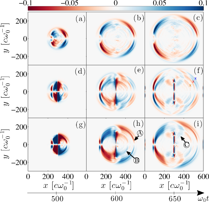
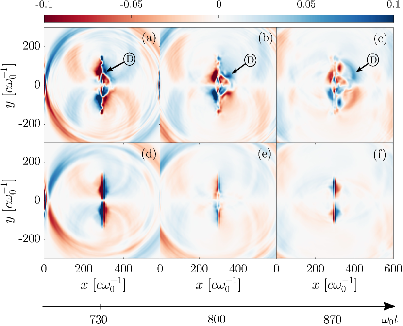
To further support this scenario, we have re-run the simulation with fixed ions. The idea is that immobile ions should prevent target deformations and,therefore, the related emission. Such behavior is clearly demonstrated in Fig. 8, which displays successive snapshots of with either mobile (top row) or immobile (bottom row) ions. The two maps at show the CTR-type emission from the target center and the edge emission from the shielding currents. The latter turns out to be weaker with immobile ions, owing to a lower laser-to-hot-electron conversion efficiency, and hence weaker shielding currents. With mobile ions, the quasistatic magnetic-field structures formed around the target center clearly reveal the local deformations of the target boundaries [see Figs. 8(a,b,c)]. At , the transversely refluxing electron currents reach the deformed central part of the target where they are deflected rightward. The resulting emission is seen to emerge from the target backside at [D in Fig. 8(c)]. This radiation will be recorded later at the probe location. With fixed ions, by contrast, the converging electron currents smoothly stream though each other [Figs. 8(d,e,f)], and so no radiation ensues.
The above radiation process is also operative at (although weaker than at because of slower target expansion), but is found to be insignificant at .
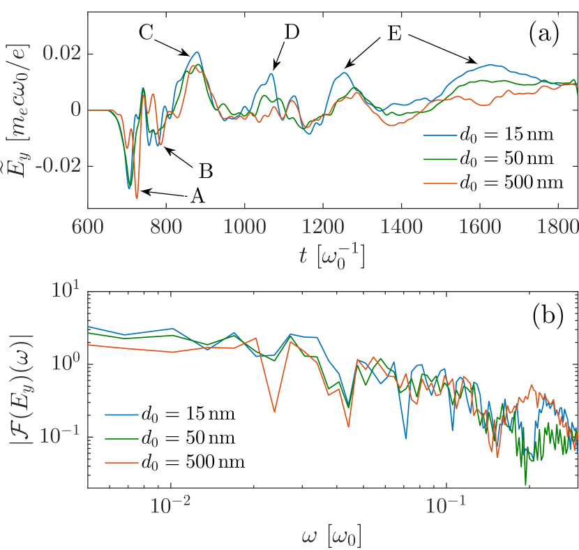
Our final comments will address the late-time () THz signals indicated by label (E) in Fig. 7(a). This figure shows that these signals, of typical duration , are enhanced in thinner targets. This translates into a stronger spectral amplitude at 15 nm around as seen in Fig. 7(b). The three broadband spectra show the same decreasing trend at higher frequencies, up to minor variations near the THz cutoff value .
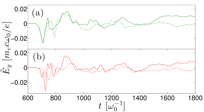
Moreover, the THz temporal signals are strengthened when allowing for mobile ions, as illustrated by Fig. 9 in the and cases. Similar properties would be expected from the sheath-induced radiation Gopal et al. (2012); *Gopal:prl:2013; *Gopal:ol:2013; Herzer et al. (2018). In particular, the target thickness dependency (e. g., the late-time emission of multiple pulses amplified in thinner targets) qualitatively agrees with the experimental findings of Jin et al. Jin et al. (2016) recalled in our introduction. However, we have not been able to provide unambiguous evidence for the sheath radiation mechanism, due to the difficulty of discriminating between the radiated fields and the quasistatic fields attached to the particles (electrons and ions) that have then reached the probe.
VI Conclusion
By means of 2D PIC simulations, we have studied numerically the various processes of THz radiation from the interaction of an ultraintense femtosecond laser pulse with submicron-thick foil targets. The complex dynamics of the laser-driven hot electrons and associated surface shielding currents leads to the emission of several successive bursts. Two main types of radiation have been identified: CTR-type waves generated from the irradiated region by the forward-accelerated, and subsequently reflected, hot electrons, and antenna-type waves produced when the shielding surface currents leave the irradiated region, reflect off the target edges, or are deflected sideways along the deformed surface of the expanding plasma bulk. These secondary radiations appear to be maximized in thin targets close to the RSIT threshold, which expand, and hence deform, the fastest. Our analysis has been carried out by resolving, for the first time, the respective contributions of the longitudinal and transverse plasma currents to the low-frequency radiation. We believe that our mapping of the different source terms will help interpret the future experiments in this field.
Author’s Contributions
All authors contributed equally to this work.
Acknowledgments
We acknowledge the “Grand Equipement de Calcul Intensif” (GENCI) for granting us access to the supercomputer IRENE under the grants No. A0070506129 and No. A0080507594.
Data availability
The data that support the findings of this study are available within the present article. Complementary data can be made available from the corresponding authors upon reasonable request.
References
- Tonouchi (2007) M. Tonouchi, Nature Photon. 1, 97 (2007).
- Bergé et al. (2019) L. Bergé, K. Kaltenecker, S. Engelbrecht, A. Nguyen, S. Skupin, L. Merlat, B. Fischer, B. Zhou, I. Thiele, and P. U. Jepsen, EPL 126, 24001 (2019).
- Nanni et al. (2015) E. A. Nanni, W. R. Huang, K.-H. Hong, K. Ravi, A. Fallahi, G. Moriena, R. J. D. Miller, and F. X. Kärtner, Nat. Commun. 6, 8486 (2015).
- Sharma et al. (2018) A. Sharma, Z. Tibai, J. Hebling, and J. A. Fülöp, J. Phys. B: At. Mol. Opt. Phys. 51, 204001 (2018).
- Curcio et al. (2018) A. Curcio, A. Marocchino, V. Dolci, S. Lupi, and M. Petrarca, Scient. Reports 8, 1052 (2018).
- LaRue et al. (2015) J. L. LaRue, T. Katayama, A. Lindenberg, A. S. Fisher, H. Öström, A. Nilsson, and H. Ogasawara, Phys. Rev. Lett. 115, 036103 (2015).
- Vicario, Monoszlai, and Hauri (2014) C. Vicario, B. Monoszlai, and C. Hauri, Phys. Rev. Lett. 112, 213901 (2014).
- Fülöp et al. (2014) J. A. Fülöp, Z. Ollmann, C. Lombosi, C. Skrobol, S. Klingebiel, L. Pálfalvi, F. Krausz, S. Karsch, and J. Hebling, Opt. Express 22, 20155 (2014).
- Hafez et al. (2016) H. A. Hafez, X. Chai, A. Ibrahim, S. Mondal, D. Férachou, X. Ropagnol, and T. Ozaki, J. Opt. 18, 093004 (2016).
- Kim et al. (2008) K. Y. Kim, A. J. Taylor, J. H. Glownia, and G. Rodriguez, Nature Photon. 2, 605 (2008).
- Nguyen et al. (2018) A. Nguyen, P. González de Alaiza Martínez, I. Thiele, S. Skupin, and L. Bergé, Phys. Rev. A 97, 063839 (2018).
- Jang et al. (2019) D. Jang, R. M. Schwartz, D. Woodbury, J. Griff-McMahon, A. H. Younis, H. M. Milchberg, and K.-Y. Kim, Optica 6, 1338 (2019).
- Koulouklidis et al. (2020) A. D. Koulouklidis, C. Gollner, V. Shumakova, V. Y. Fedorov, A. Pugžlys, A. Baltuška, and S. Tzortzakis, Nat. Commun. 11, 292 (2020).
- Oh et al. (2013) T. I. Oh, Y. S. You, N. Jhajj, E. W. Rosenthal, H. M. Milchberg, and K. Y. Kim, Applied Physics Letters 102, 201113 (2013).
- Déchard et al. (2018) J. Déchard, A. Debayle, X. Davoine, L. Gremillet, and L. Bergé, Phys. Rev. Lett. 120, 144801 (2018).
- Déchard, Davoine, and Bergé (2019) J. Déchard, X. Davoine, and L. Bergé, Phys. Rev. Lett. 123, 264801 (2019).
- Leemans et al. (2003) W. P. Leemans, C. Geddes, J. Faure, C. Tóth, J. van Tilborg, C. B. Schroeder, E. Esarey, G. Fubiani, D. Auerbach, B. Marcelis, M. A. Carnahan, R. A. Kaindl, J. Byrd, and M. C. Martin, Phys. Rev. Lett. 91, 074802 (2003).
- Schroeder et al. (2004) C. B. Schroeder, E. Esarey, J. van Tilborg, and W. P. Leemans, Phys. Rev. E 69, 016501 (2004).
- Liao et al. (2019) G. Liao, Y. Li, H. Liu, G. G. Scott, D. Neely, Y. Zhang, B. Zhu, Z. Zhang, C. Armstrong, E. Zemaityte, P. Bradford, P. G. Huggard, D. R. Rusby, P. McKenna, C. M. Brenner, N. C. Woolsey, W. Wang, Z. Sheng, and J. Zhang, Proc. Nat. Ac. Sci. 116, 3994 (2019).
- Kruer and Estabrook (1985) W. L. Kruer and K. Estabrook, Phys. Fluids 28, 430 (1985).
- Debayle et al. (2013) A. Debayle, J. Sanz, L. Gremillet, and K. Mima, Phys. Plasmas 20, 053107 (2013).
- Brunel (1987) F. Brunel, Phys. Rev. Lett. 59, 52 (1987).
- Bauer and Mulser (2007) D. Bauer and P. Mulser, Phys. Plasmas 14, 023301 (2007).
- May et al. (2011) J. May, J. Tonge, F. Fiuza, R. A. Fonseca, L. O. Silva, C. Ren, and W. B. Mori, Phys. Rev. E 84, 025401 (2011).
- Forslund et al. (1975) D. W. Forslund, J. M. Kindel, K. Lee, E. L. Lindman, and R. L. Morse, Phys. Rev. A 11, 679 (1975).
- Xu et al. (2006) H. Xu, Z.-M. Sheng, J. Zhang, and M. Y. Yu, Phys. Plasmas 13, 123301 (2006).
- Kemp et al. (2014) A. J. Kemp, F. Fiuza, A. Debayle, T. Johzaki, W. B. Mori, P. K. Patel, Y. Sentoku, and L. O. Silva, Nucl. Fusion 54, 054002 (2014).
- Zheng et al. (2003) J. Zheng, K. A. Tanaka, T. Miyakoshi, Y. Kitagawa, R. Kodama, T. Kurahashi, and T. Yamanaka, Phys. Plasmas 10, 2994 (2003).
- Bellei et al. (2012) C. Bellei, J. R. Davies, P. K. Chauhan, and Z. Najmudin, Plasma Phys. Control. Fusion 54, 035011 (2012).
- Ding and Sheng (2016) W. J. Ding and Z. M. Sheng, Phys. Rev. E 93, 063204 (2016).
- Tokita et al. (2015) S. Tokita, S. Sakabe, T. Nagashima, M. Hashida, and S. Inoue, Sci. Rep. 5, 8268 (2015).
- Ginzburg (1982) V. L. Ginzburg, Phys. Scr. T2A, 182 (1982).
- Myatt et al. (2007) J. Myatt, W. Theobald, J. A. Delettrez, C. Stoeckl, M. Storm, T. C. Sangster, A. V. Maximov, and R. W. Short, Phys. Plasmas 14, 056301 (2007).
- Poyé et al. (2015) A. Poyé, S. Hulin, M. Bailly-Grandvaux, J. L. Dubois, J. Ribolzi, D. Raffestin, M. Bardon, F. Lubrano-Lavaderci, E. D’Humières, J. J. Santos, P. Nicolaï, and V. Tikhonchuk, Phys. Rev. E 91, 043106 (2015).
- Nakamura et al. (2004) T. Nakamura, S. Kato, H. Nagatomo, and K. Mima, Phys. Rev. Lett. 93, 265002 (2004).
- Zhuo et al. (2017) H. B. Zhuo, S. J. Zhang, X. H. Li, H. Y. Zhou, X. Z. Li, D. B. Zou, M. Y. Yu, H. C. Wu, Z. M. Sheng, and C. T. Zhou, Phys. Rev. E 95, 013201 (2017).
- Smith (2001) G. S. Smith, Am. J. Phys. 69, 288 (2001).
- Wagner et al. (2016) F. Wagner, O. Deppert, C. Brabetz, P. Fiala, A. Kleinschmidt, P. Poth, V. A. Schanz, A. Tebartz, B. Zielbauer, M. Roth, T. Stöhlker, and V. Bagnoud, Phys. Rev. Lett. 116, 205002 (2016).
- Mora (2003) P. Mora, Phys. Rev. Lett. 90, 185002 (2003).
- Mora (2005) P. Mora, Phys. Rev. E 72, 056401 (2005).
- Gopal et al. (2012) A. Gopal, T. May, S. Herzer, A. Reinhard, S. Minardi, M. Schubert, U. Dillner, B. Pradarutti, J. Polz, T. Gaumnitz, M. C. Kaluza, O. Jackel, S. Riehemann, W. Ziegler, H.-P. Gemuend, H.-G. Meyer, and G. G. Paulus, New J. Phys. 14, 083012 (2012).
- Gopal et al. (2013a) A. Gopal, S. Herzer, A. Schmidt, P. Singh, A. Reinhard, W. Ziegler, D. Brömmel, A. Karmakar, P. Gibbon, U. Dillner, T. May, H.-G. Meyer, and G. G. Paulus, Phys. Rev. Lett. 111, 074802 (2013a).
- Gopal et al. (2013b) A. Gopal, P. Singh, S. Herzer, A. Reinhard, A. Schmidt, U. Dillner, T. May, H.-G. Meyer, W. Ziegler, and G. G. Paulus, Opt. Lett. 38, 4705 (2013b).
- Jin et al. (2016) Z. Jin, H. B. Zhuo, T. Nakazawa, J. H. Shin, S. Wakamatsu, N. Yugami, T. Hosokai, D. B. Zou, M. Y. Yu, Z. M. Sheng, and R. Kodama, Phys. Rev. E 94, 033206 (2016).
- Herzer et al. (2018) S. Herzer, A. Woldegeorgis, J. Polz, A. Reinhard, M. Almassarani, B. Beleites, F. Ronneberger, R. Grosse, G. G. Paulus, U. Hubner, T. May, and A. Gopal, New J. Phys. 20, 063019 (2018).
- Vshivkov et al. (1998) V. A. Vshivkov, N. M. Naumova, F. Pegoraro, and S. V. Bulanov, Phys. Plasmas 5, 2727 (1998).
- d’Humières et al. (2005) E. d’Humières, E. Lefebvre, L. Gremillet, and V. Malka, Phys. Plasmas 12, 062704 (2005).
- Esirkepov, Yamagiwa, and Tajima (2006) T. Esirkepov, M. Yamagiwa, and T. Tajima, Phys. Rev. Lett. 96, 105001 (2006).
- Brantov et al. (2015) A. V. Brantov, E. A. Govras, V. Y. Bychenkov, and W. Rozmus, Phys. Rev. ST Accel. Beams 18, 021301 (2015).
- Ferri et al. (2020) J. Ferri, E. Siminos, L. Gremillet, and T. Fülöp, arXiv e-prints , arXiv:2004.00953 (2020), arXiv:2004.00953 .
- Yu et al. (2000) W. Yu, V. Bychenkov, Y. Sentoku, M. Y. Yu, Z. M. Sheng, and K. Mima, Phys. Rev. Lett. 85, 570 (2000).
- Thévenet et al. (2016) M. Thévenet, A. Leblanc, S. Kahaly, H. Vincenti, A. Vernier, F. Quéré, and J. Faure, Nat. Phys. 12, 355 (2016).
- Liu et al. (2013) J.-L. Liu, M. Chen, J. Zheng, Z.-M. Sheng, and C.-S. Liu, Phys. Plasmas 20, 063107 (2013).
- Stark et al. (2017) D. J. Stark, L. Yin, B. J. Albright, and F. Guo, Physics of Plasmas 24, 053103 (2017).
- Ferri et al. (2018) J. Ferri, L. Senje, M. Dalui, K. Svensson, B. Aurand , M. Hansson, A. Persson, O. Lundh, C. G. Wahlström, L. Gremillet, E. Siminos, T. C. DuBois, L. Yi, J. L. Martins, and T. Fülöp, Phys. Plasmas 25, 043115 (2018).
- Liao et al. (2016) G. Q. Liao, Y. T. Li, C. Li, H. Liu, Y. H. Zhang, W. M. Jiang, X. H. Yuan, J. Nilsen, T. Ozaki, W. M. Wang, Z. M. Sheng, D. Neely, P. McKenna, and J. Zhang, Plasma Phys. Control. Fusion 59, 014039 (2016).
- Carron (2000) N. J. Carron, Prog. Electromagn. Res. 28, 147 (2000).