Off-axis vortex beam propagation through classical optical system in terms of Kummer confluent hypergeometric function
Abstract
The analytical solution for the propagation of the laser beam with optical vortex through the system of lenses is presented. The optical vortex is introduced into the laser beam (described as Gaussian beam) by spiral phase plate. The solution is general as it holds for the optical vortex of any integer topological charge, the off-axis position of the spiral phase plate and any number of lenses. Some intriguing conclusions are discussed. The higher order vortices are unstable and split under small phase or amplitude disturbance. Nevertheless, we have shown that off-axis higher order vortices are stable during the propagation through the set of lenses described in paraxial approximation, which is untypical behavior. The vortex trajectory registered at image plane due to spiral phase plate shift behaves like a rigid body. We have introduced a new factor which in our beam plays the same role as Gouy phase in pure Gaussian beam.
I Introduction
The question of propagation of light fields containing optical vortices Vasnetsov and Staliunas (1999); Soskin and Vasnetsov (2001); Dennis et al. (2009) is getting attention in many fields of modern optical science nowadays. The fundamental case of such a field is vortex beam - the well-defined, single beam (as for example LG beam Kotlyar et al. (2018); Arora and Lu (1994)), carrying the optical vortex of any order. Many different problems concerning propagation of the vortex beam have been considered in the literature so far. Some of them consider optical fields containing the lattice of vortices generated for example by three or more plane or spherical waves interference Masajada and Dubik (2001); Senthilkumaran et al. (2012); Ruben and Paganin (2007); Vyas and Senthilkumaran (2007); or so called composed vortices, i.e. vortices which are generated by two or more overlapping beams Vasnetsov et al. (2005); Bekshaev et al. (2004); Yang et al. (2011); Khonina et al. (2018); Bouchal and Bouchal (2017); Sokolenko et al. (2018); Szatkowski et al. (2020).
The study on single vortex beam propagation has started with the most basic problem, that is propagation of the fundamental vortex beam in a free space Bazhenov et al. (1992); Indebetouw (1993); Rozas et al. (1997). Next, the problem of vortex beam propagation through the simple optical element revealing circular symmetry was reported Topuzoski and Janicijevic (2009); Khonina et al. (1992). Here, the most important part for our considerations are papers devoted to Gaussian beam propagation through the spiral phase plate (SPP) Beijersbergen et al. (1994); Allen et al. (1999); Swartzlander Jr (2006); Khoroshun (2010); Kotlyar et al. (2005); Khonina et al. (2015). SPP is now one of the most common ways of introducing optical vortex into the laser beam. In more advanced approaches the propagation of vortex beam with broken symmetry or through the system with broken symmetry (like for example diffraction by half-plane Masajada (2000); Bekshaev et al. (2016) or a phase step Masajada et al. (2009); Spektor et al. (2008)) was studied. Most of these asymmetrical cases were studied combining numerical and/or strongly approximated analytical method, especially in case of higher order vortices Masajada et al. (2008); Anzolin et al. (2009); Singh et al. (2009a, b); Masajada et al. (2011); Dennis and Götte (2012); Augustyniak et al. (2012); Popiołek-Masajada et al. (2014); Savelyev and Khonina (2015). Another highly asymmetrical problem is a vortex beam propagation through the turbid media (e.g. atmosphere) Aksenov and Pogutsa (2013); Morgan et al. (2016); Soifer et al. (2016).
In the paper Anzolin et al. (2009) the analysis of the Gaussian beam propagation through the off-axis SPP in Fraunhofer approximation is studied. Authors have focused their attention on the vortex point displacement measured by inspecting the asymmetry in intensity distribution at the far field. In the present paper we analyze asymmetrical optical system with Fresnel diffraction theory, which is more general than Fraunhofer one. The analysis of the off-axis high-order vortices is a difficult task. The integrals become highly complicated and some typical tricks often used in the calculations cannot be applied. The good example is stationary phase method Stamnes (2017), which cannot be used since the phase changes very fast in the vicinity of the vortex point. That is the reason why there are only few publications regarding the exact solutions of asymmetric higher order vortex propagation. In paper Kotlyar et al. (2017) the elliptic vortex beam propagation is studied. The paper Rumi et al. (2017) describes the generation of the higher order vortex beam by discretizing spiral phase plate. In paper Berry (2004) the generation of vortex beam through fractional spiral phase plate is studied. In papers Bekshaev and Karamoch (2008); Bekshaev and Sviridova (2010) the propagation through off-axis hologram generating the optical vortices is analyzed, also including the effects of misalignment. In papers Płocinniczak et al. (2016); Płociniczak et al. (2016) we have provided a solution for asymmetrical vortex propagation in optical vortex scanning microscope (OVSM) presented schematically in Fig. 1. In this paper we propose more general solution in terms of Kummer confluent hypergeometric function which can be used for a system of arbitrary number of lenses.
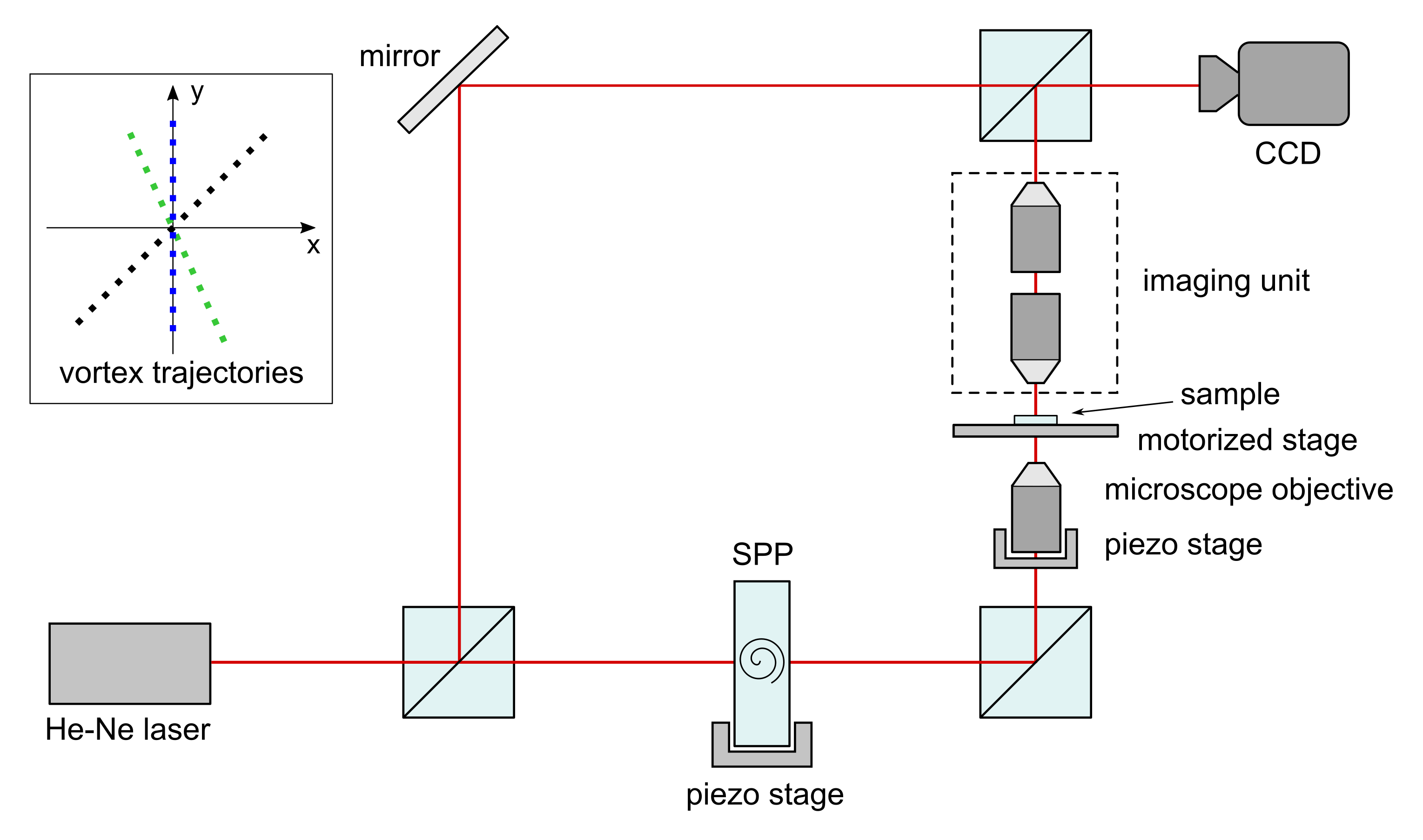
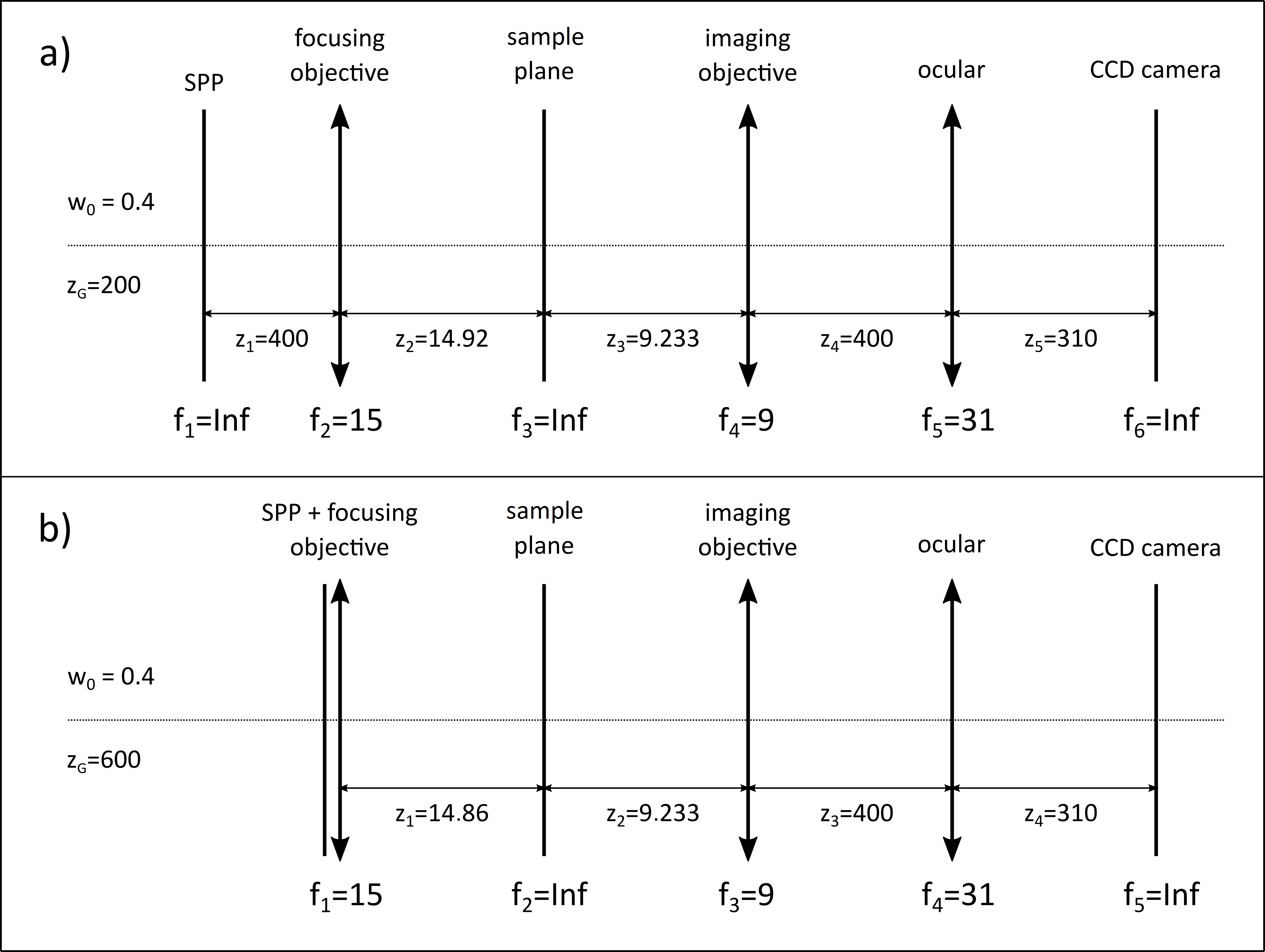
In this paper the optical system shown schematically in Fig. 2 is studied. The system represents the object arm of the OVSM shown in Fig. 1 (in experiment, the reference arm is necessary for reconstructing both amplitude and phase of the object beam. Obviously, in analytical and numerical calculations we do not need it). The system is divided into blocks. Each block consists of one or more elements and is represented by its transmittance function (in case of single element) or the product of the transmittance functions (when there are two or more elements in the given block). In our first approach Płocinniczak et al. (2016) the OVSM was reduced to a single block consisting of three elements, i.e. incident Gaussian beam, SPP and focusing lens considered as a single thin element. The image was calculated at the sample plane (noted as sample in Fig. 1). It should be noticed that the SPP can be moved perpendicularly to the optical axis, which breaks the system symmetry. In result the vortex point moves inside the focused beam, but the range of this movement is highly reduced due to focusing lens. The inset in Fig. 1 shows the exemplary vortex trajectories as registered in our experimental system. In this way the sample can be scanned with the vortex point (i.e. point where the phase is singular). This technique is named the Internal Scanning Method (ISM) Masajada et al. (2011); Augustyniak et al. (2012); Płocinniczak et al. (2016); Płociniczak et al. (2016); Popiołek-Masajada et al. (2017, 2019). In the paper Płociniczak et al. (2016) the system built of three blocks was analyzed. The first block consisted of incident Gaussian beam, SPP and focusing lens, the second was just the sample plane, and the third contained a single imaging lens. Here, we extend the analysis to the fully expanded system shown in Fig. 2(b).
Our analysis was performed within the frame of scalar diffraction theory in Fresnel approximation Goodman (2005). The Fresnel diffraction integral for the first block shown in Fig. 2(b) has a form
| (1) |
where is transmittance function of the SPP, is an incident Gaussian beam, is a transmittance function of the focusing lens.
| (2a) | |||
| (2b) | |||
| (2c) | |||
| (2d) | |||
| (2e) |
is a topological charge of the optical vortex; it is an integer – positive or negative, is a beam waist (of the Gaussian beam), is a focal length of the focusing lens.
Instead of moving the SPP off the optical axis by the distance we moved the rest of the system (including the screen) by the same , which simplified further calculations. As was shown in Płocinniczak et al. (2016) the integral Eq. (1) had a solution
| (3) |
where
| (4a) | |||
| (4b) | |||
| (4c) | |||
| (4d) | |||
| (4e) |
The parameters and are
| (4f) |
| (4g) |
The main part of this solution is function Kappa .
| (5a) | |||
| where | |||
| (5b) | |||
We have obtained an interesting result showing that a system having more blocks (with lenses or just planes) can still be described by Kappa function, but with different coefficients , , , , . The number of blocks in the system is indicated by superscript () as it has been already done in Eq. (3) and Eq. (4g). In paper Płociniczak et al. (2016) we calculated explicitly the coefficients , , , , up to , and postulated that it can be done for any (). In this paper we derived a recurrence formula for the coefficient for any number of blocks (any ()), which is actually a formal proof of our previous claim.
The function Kappa was denoted previously as Płocinniczak et al. (2016); Płociniczak et al. (2016). Since that time we have improved and generalized our solution. Now the function is rewritten in more useful form. In order not to confuse both versions, we denote the present version by capital Kappa .
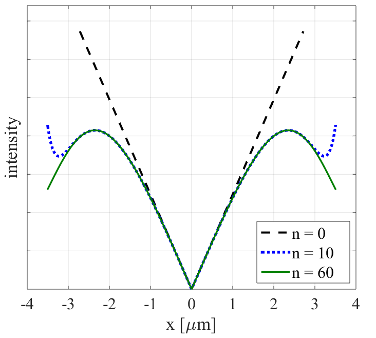
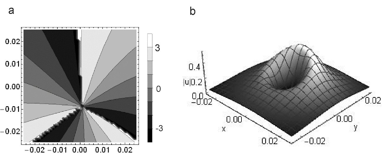
As it was shown in papers Płocinniczak et al. (2016); Płociniczak et al. (2016), close to the vortex axis the term is sufficient to evaluate the vortex beam. Figure 3 illustrates this fact, but now it is plotted for the four-block system shown in Fig. 2(b). This is a useful result for us, as we analyze the OVSM images at the central part of the beam, where the approximation well represents phase and amplitude distribution of our beam.
Our goal was to represent the entire object arm of the OVSM as presented in Fig. 2(a). Now the SPP can be separated from the focusing lens which means that focal length for the first block (i.e. SPP block) is . Next there is a focusing lens with focal length mm followed by the sample plane for which the focal length is also infinite . The third block is the imaging lens with focal length mm and the last one is the ocular lens with focal length mm, after which we have observation plane (screen). Unfortunately, for the reasons given later in the manuscript the full system could not be analyzed with Kappa function. The SPP cannot be separated from the focusing lens. Therefore, we have to switch to the system shown in Fig. 2(b). In this paper we will analyze this system showing the efficiency of our formulas. As can be noticed from Fig. 2(b), in our model a sample plane is treated as a separate block. In this way we are able to enhance our calculations in order to analyze the influence of a simple phase object on the vortex beam. Thus, the system shown in Fig. 2(b) prepares us for this next step.
Certainly, all the blocks may have different focal lengths and positions than the ones shown in Fig. 2 and the Kappa function will still work. However, the important thing is that the first element must be the block containing the SPP, focusing lens and Gaussian beam.
The present paper is organized as follows. In section II the extension of our formulas as well as their closed form for the system consisting of any number of lenses is discussed. In section III we discussed the role of coefficient . In section IV we show the efficiency of our formulas by discussing the effect of vortex trajectory rotation. Section V concludes the paper.
II Analytical part
In this part our previous results will be extended. In order to build more relevant model of the OVSM we have derived the explicit formula for coefficients , , , , up to , just to analyze the OVSM system shown in Fig. 2(b).
| (6a) | |||
| (6b) | |||
| (6c) | |||
| (6d) | |||
| (6e) | |||
| (6f) | |||
| (6g) | |||
| (6h) |
where the meaning of and can be read from Fig. 2), ,…, are lens thicknesses. In case of a simple plane we put .
Following this path a general iterative formulas for coefficient of any () index can be derived. The formulas have a form
| (7a) | |||
| (7b) |
| (8a) | |||
| (8b) | |||
| (8c) | |||
| (8d) | |||
| (8e) | |||
| (8f) | |||
| (8g) |
The derivation of the above is presented in Appendix A.
The sums in Kappa function are convergent provided that a series of conditions are hold
| (9) |
Very similar formulas can be derived for negative vortex charge. In that case we can use the same Kappa function but with some multiplying expression and coefficient multiplied by .
| (10) |
The derivation of this formula is presented in Appendix B.
We have also derived a closed formula, but with a special function, which is given below. The derivation is discussed in the Appendix C.
| (11a) | |||
| (11b) |
where is the Kummer confluent hypergeometric function Abramowitz and Stegun (1972). The calculations using closed formula are much faster, but as we will show both formulas Eq. (3) and Eq. (11b) are helpful in understanding the vortex beam propagation through our system.
The sum of two coefficients in Eq. (8b)-(8c) is a complex expression which can be easily decomposed into real and imaginary part. From Eq. (8b)-(8c) we got for real part
| (12) |
And for imaginary part
| (13) |
The form of coefficients , , depends on the value of .
| (14a) | |||
| (14b) | |||
| (14c) |
For example for we get
| (15a) | |||
| (15b) | |||
| (15c) |
Formulas in Eq. (12) and Eq. (13) show that y-coordinate is a member of imaginary part and x-coordinate is a member of real part of the expression. This leads us to simple formulas for vortex point trajectory. The vortex point (zero amplitude point) is at the place where both imaginary and real part are equal to zero Vasnetsov and Staliunas (1999); Soskin and Vasnetsov (2001); Dennis et al. (2009).
| (16a) | |||
| (16b) |
From the above formula we may conclude that the vortex trajectory as a function of , for the given z is a straight line. We may also find a plane where the vortex trajectory is perpendicular to the SPP shift. Using Eq. (16b) the condition is
| (17) |
In the paper Płocinniczak et al. (2016) we have formulated the hypothesis that the higher order vortices () do not split even when . The higher order vortices are classified as structurally unstable Nye (1999), i.e. they are supposed to split into single order vortices even under small phase or amplitude perturbation Ricci et al. (2012); Neo et al. (2014); Zambrana-Puyalto et al. (2016). Nevertheless, the formulas in Eq. (11b) proof the stability hypothesis in an explicit form. The factors in front of the Kummer confluent hypergeometric function are just a vortex term.
| (18) |
The place where real and imaginary part of + is zero indicates the position of the vortex point of the -th order. Since the whole term is at power , the -order vortex does not split for any . The result is very interesting, which is illustrated in Fig. 4.
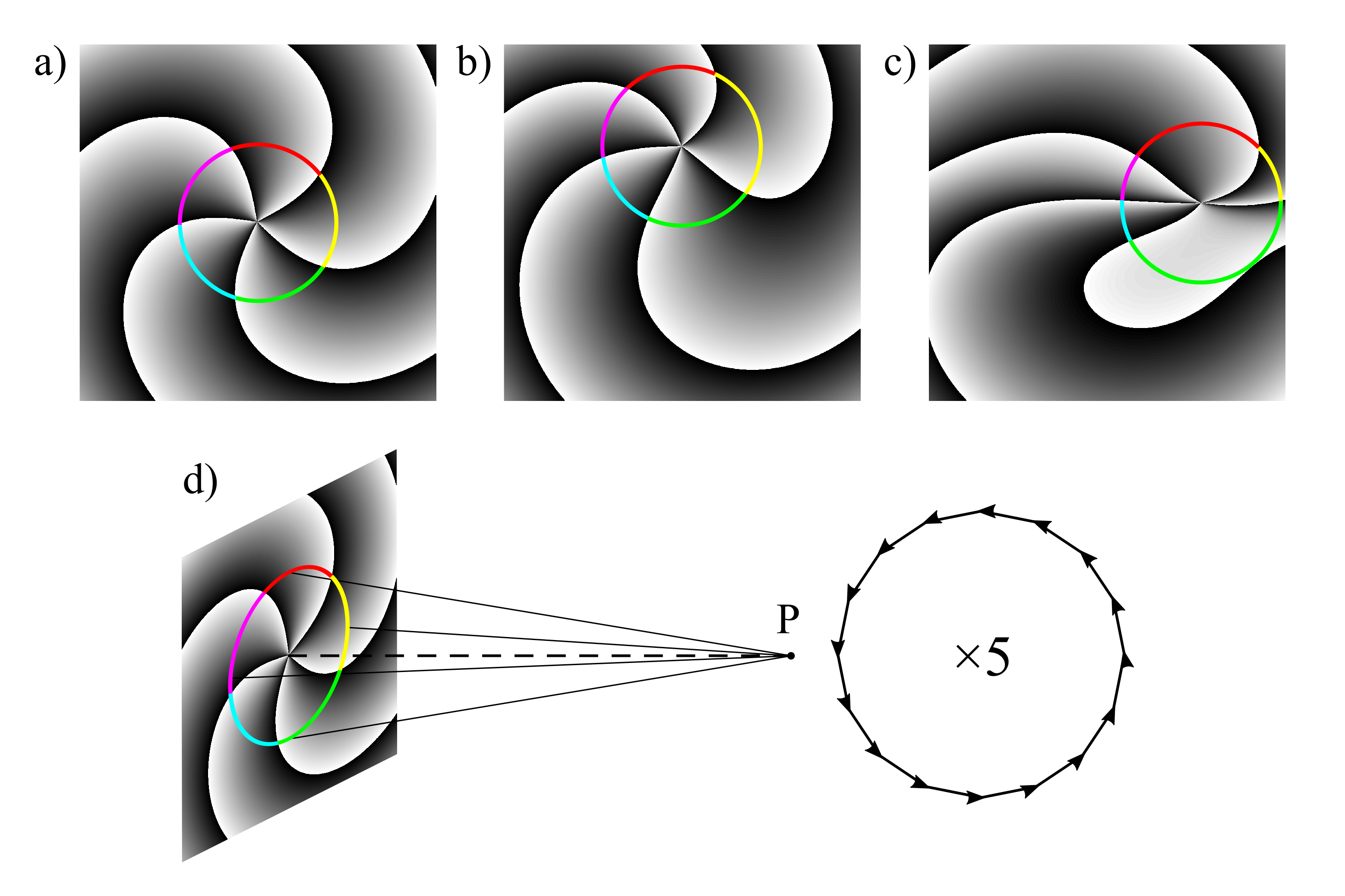
The situation would not be strange if the higher order optical vortex were stable for a given non-zero value . However, changing the continuously breaks the circular symmetry of the phase distribution at the SPP plane with no harm for the higher order OV stability. We could also start our analysis at the sample plane, where both phase and amplitude distribution symmetry is broken (Fig. 5). Nevertheless, the propagation of this input beam through any number of lenses will not split the higher order vortices.
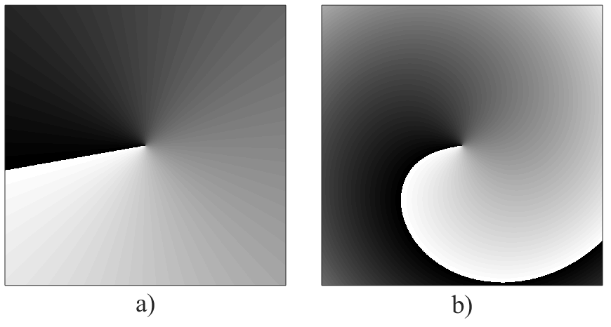
We can go even further. Adding the term inside the bracket in Eq. (18) and multiplying or coefficients by any number, but in such a way that the coefficients by remain real (or become imaginary) and coefficient by remain imaginary (or become real) may change the position of the vortex point and its phase distribution (Fig. 5(c)) but still the higher order vortices will be stable while propagating through our system. However, changing other parameters, like for example binomial factor by coefficients in Eq. (5b) splits the higher order vortices immediately (Fig. 6).
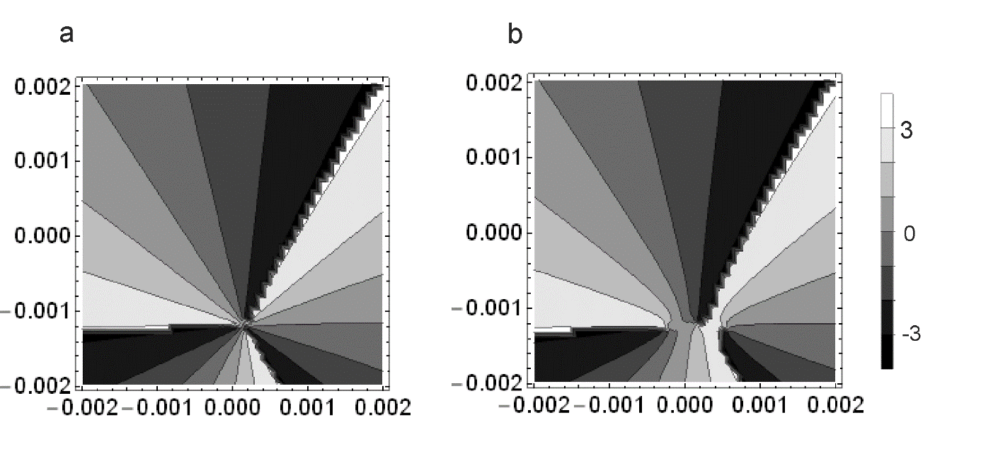
To summarize this part: We have shown that the higher order vortices when propagating through the set of classical lenses described in paraxial approximation will not split regardless of asymmetry introduced by the off axis position of the SPP. Moreover, we may perform some more symmetry breaking operation (as shown in Fig. 4(c)) in Eq. (8c)-(8d), provided that the coefficients by remain real (or imaginary) and by imaginary (or real). So, the conclusion is that the very basic optical system does not split the higher order vortices even if the input phase and amplitude distribution is highly non-symmetrical. In many cases such an unusual stability results from deeper physical rules. There is a question if this is also a case here. So far we have no answer to this question. What we can learn now is that classical optical system is somewhat special, at least when being described in paraxial approximation and illuminated by Gaussian beam with the vortex beam introduced by SPP. In the next section the special role of the coefficient will be studied.
III Coefficient A
In our further discussion we will refer to two specific examples of the OVSM models. One with the separated SPP plate and focusing lens (Fig. 2(a)) and the second one with SPP plate and focusing lens working as single thin element (Fig. 2(b)).
The coefficient has relatively simple form. It depends neither on the and coordinates nor on SPP shift . However, it plays a crucial role in vortex beam phase evolution. Unfortunately it cannot be totally taken outside the first sum in Kappa function. On the contrary, in Eq. (4g) it can be entirely assimilated inside the first sum, but in the present form some mathematical aspects can be noticed in a more clear way.
The first important point is that the coefficient is responsible for breaking the Kappa function convergence. In the OVSM this happens when the SPP is separated from the focusing lens, and coefficient has a singular point (Fig. 7(a,b)). At first we will analyze the system with two blocks, the SPP and the focusing lens (sample plane is an observation plane in this case), so we need the second order coefficient . The coefficient contributes to the Kappa function as , so the term in front of the first sum takes form (for ).
| (19) |
There exist a range of such positive for which the conditions in Eq. (9) fail. In particular there is a value that the equals zero and the whole term in Eq. (19) becomes zero. Thus, the whole Kappa function is equal to zero, which shows that it does not reflect the true behavior of the focused vortex beam. Moreover, the Kappa function encounters a -jump in this point. This value can be computed from the formula
| (20) |
Fig. 7(a,b) illustrates the problem. As we can see for the mm (calculated from Eq. (20)) the term equals zero.
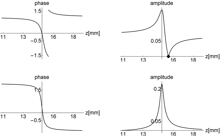
When the SPP and focusing lens are joined, we only need a coefficient which has a simple form, free of our problem (at least for the OVSM optical system). This is illustrated in Fig. 7(c,d). The higher order terms () behave in a similar way. When the SPP and focusing lens work as a single element, they meet the conditions in Eq. (9), for a reasonable OVSM configuration. When the set of conditions in Eq. (9) is more complicated. The detailed study of this problem would explode the volume of this paper, so we will not follow this path. Important thing is that when SPP and focusing lens work separately, condition in Eq. (9) fails for any in case of reasonable OVSM configurations. From practical point of view it is enough to check if the factor behaves like in Fig. 7(c,d), which is a case in the system shown in Fig. 2(b). It is worth noticing here that when using the ISM all parameters are fixed, so the test for conditions in Eq. (9) is not difficult. When we move any element of our system along the optical axis the conditions in Eq. (9) have to be checked for the whole range of coordinates.
For the reason explained above we cannot use our formulas to the system shown in Fig. 2(a). Instead, we have to limit our study to the system shown in Fig. 2(b), when both SPP and focusing lens work together. Certainly for the forbidden area the numerical modeling of our optical system is still possible and effective.
We can also find coefficient inside the first sum in Kappa function. Now, we multiply this terms by , located in front of the first sum, so we have
| (21a) | |||
| (21b) |
The first term (for ) has the largest influence on the phase and amplitude of the Kappa function The next terms rapidly drop in their values. The plot in Fig. 8 is done for , but it represents the typical curve for expressions in Eq. (21a)-(21b) for any , provided that we avoid the forbidden area defined by conditions (9). As we can see the part for strongly dominates over the part for . The next terms (for ) are invisible in the figure scale. This domination is particularly strong at the beam center, when and coordinates are small (Fig. 3). When the and become larger, the coefficient grows rapidly with increasing and things become more complicated.
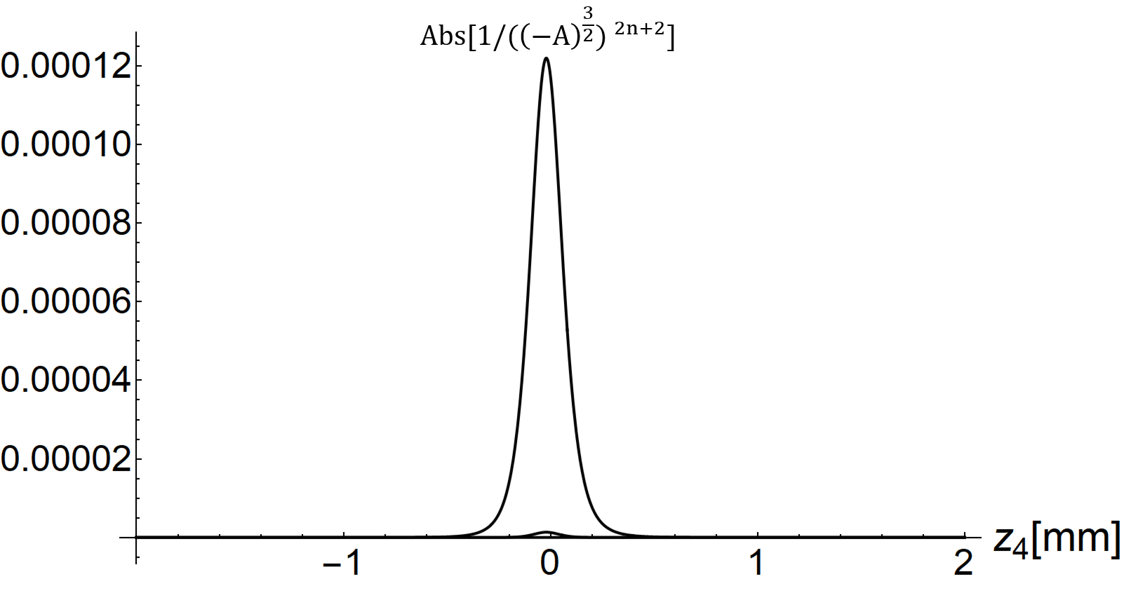
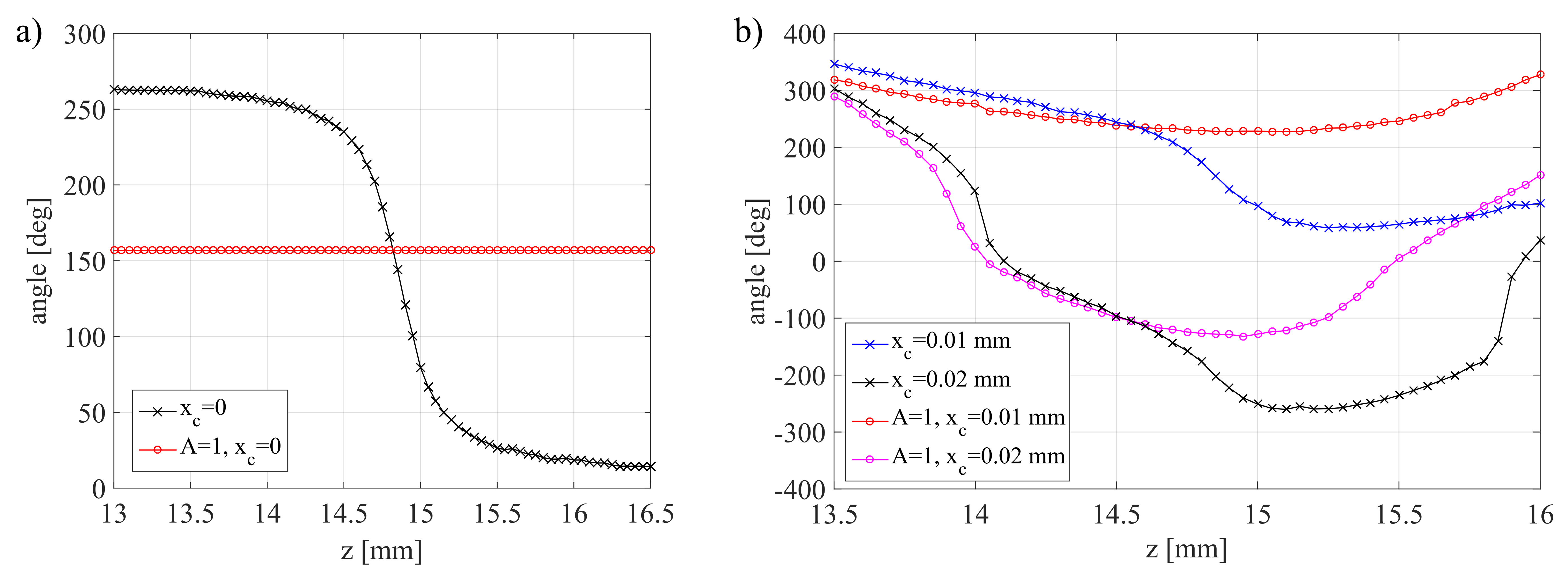
Figure 7(c) suggests that the coefficient may play a primary role in phase evolution after the SPP, i.e. when changing the position of any element behind the SPP or SPP and focusing lens themselves. This is illustrated in Fig. 9(a). If and , there is no phase rotation when changing the position of the focusing lens along the z-axis. We can conclude that in the OVSM system the coefficient plays, in some respect, the similar role as the Gouy phase in the Gaussian beam. When the things become more complicated. The off-axis position of the SPP plate introduces a phase value dependence on being inside the coefficient (Fig. 9(b)).
The other coefficients (but , ) play minor role. The coefficient and are responsible for the vortex trajectory evolution as a function of SPP shift . This dependence is linear, but as has been already shown, the direction of vortex trajectory becomes perpendicular to SPP trajectory when the condition in Eq. (17) holds. In the previous papers Płocinniczak et al. (2016); Płociniczak et al. (2016) this fact was proved for the small . Having the formulas in Eq. (11b) we can conclude that they hold for any . In paper Popiołek-Masajada et al. (2019) precise experiments were reported which confirm the theoretical results.
The coefficient collects all constant factors. It must be observed when we analyze the rotation of the beam phase while moving the first block in the optical system along the z-axis. When the first element moves away or toward the laser source, the phase of the incident Gaussian beam changes. This incident phase is a part of coefficient .
The coefficient multiplies the first sum in function Kappa. Due to the factor, the coefficient is responsible for the equiphase lines curvature (Fig. 10). When the equiphase lines are straight (for ). Since the coefficient contributes to the Kappa function as , where is an imaginary part of the coefficient, and typically its contribution to the amplitude is small, especially for small .
IV The ice-skater effect
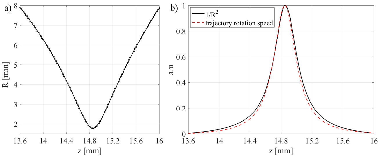
To see the effectiveness of our formulas we study the correlation between the focused beam radius and vortex trajectory rotation (see the inset in Fig. 1). The hypothesis was that the vortex trajectory behaves like a rigid body. Consequently we assumed that in the closed system of a focused vortex beam the angular momentum is conserved, thus . Regardless of the assumed model (point mass, flat disk, cylinder, etc.), the moment of inertia is always proportional to the squared distance from the rotation axis, i.e. . Therefore, the rotational speed of the vortex trajectory shall satisfy . In our case, is the first derivative of the trajectory inclination angle with respect to () and is the radius of the vortex bright ring, i.e. the distance between points of zero and maximal intensity (e.g. m for the vortex analyzed in Fig. 3). Both the radius of the converging vortex beam and the rotational speed of the trajectory depend on the axial distance . Obviously, as approaches the focal point, the vortex radius decreases whereas the rotations speed up. As the beam focusses, the radius reaches its minimum and the speed is maximal. This is a direct analogy to the ice skater pulling their arms in for a faster spin. Such a rigid body mechanics approach to the vortex beam has been already studied by Bekshaev et. al. Bekshaev et al. (2004), for free propagating Gaussian beam with optical vortex. The authors concluded that it is related to the Gouy phase dynamics. We have stated that the coefficient plays the role of the Gouy phase in our case. Indeed, from Eq. (12)-(13) we may calculate the angle of the trajectory inclination as
| (22) |
For we get
| (23) |
Calculating the angle of the equiphase line for the coefficient we get exactly the same formula.
Here we present the results calculated at the exit of the setup (camera plane) shown in Fig. 2(b). The default z-position is where the the focal point of the beam lies very close to the critical plane (plane where the trajectory is perpendicular to the SPP shift ). Defocusing is performed by moving the focusing objective along the optical axis without changing the position of other elements. Thus, the plane at which the vortex beam is imaged is at different distances from the focus resulting in different vortex radii, as shown in Fig. 11(a). These calculations require running the Kappa function once for each point on the graph. On the other hand, computing the vortex trajectory rotation speed is much easier. In paper Augustyniak et al. (2012) the formula for was given as:
| (24) |
In fact the formula in Eq. (24) was derived for the vortex trajectory rotation at the sample plane for the approximated linear case (). But the new formulas in Eq. (11b) allow to extent their applicability for general case. The classical imaging preserves the vortex trajectory orientation as was shown experimentally in Płociniczak et al. (2016); Popiołek-Masajada et al. (2017). So we expect that the angle rotation at the image plane is the same as in the sample plane.
The obtained relation between the rotational speed and the defocusing is presented in Fig. 11(b), red. Applying the above rigid-body reasoning, was compared with the inverse square of the vortex radius (Fig. 11(b), black). There is a clear agreement between the two curves supporting the hypothesis of rigid-like behavior of vortex trajectory.
V Conclusions
There is a growing interest in exact theory describing the propagation of the optical vortex beams in optical system, in particular in a system with broken symmetry. The reasons are both understanding the physics of electromagnetic waves, and practical applications. Some examples concerning both science or applications can be found in Bekshaev et al. (2004); Bouchal and Bouchal (2017); Swartzlander Jr (2006); Anzolin et al. (2009); Popiołek-Masajada et al. (2017); Ferrando and García-March (2016); Gibson et al. (2004), but the list of papers is much longer. In this paper we have enhanced the results presented in our former works Płocinniczak et al. (2016); Płociniczak et al. (2016). We have derived the coefficient for Kappa function for any numbers of elements. We have also enhanced the formulas for the vortex trajectory. Moreover, we have found a closed form of our solution in Eq. (11b) using the special function. This new form proved that in classical optical system, the higher order vortices do not split even if the circular symmetry is broken. This is true under the conditions of paraxial approximation. This result is truly surprising. It is hard to check it experimentally. We cannot use an optical system in paraxial approximation. Moreover, any real system introduces errors which break the beam symmetry in a way different than allowed by our theory. This immediately splits the higher order vortices forming a constellation of the first order ones. Nevertheless, the experiment reported in Płocinniczak et al. (2016) suggested the mass center of such a constellation moves as ideal higher order vortex.
The study on coefficient have shown that it is responsible for breaking the conditions in Eq. (9). In result we cannot analyze the OVSM system with separated SPP plate and focusing lens. The coefficient has an important role in the rotation of vortex beam phase, which is similar to the role of the Gouy phase in Gaussian beam. The second important factor is the SPP shift . When we are close to vortex core we can limit the sum range (in Kappa function) to , which is also the result of the coefficient (Fig. 8).
We have shown that the vortex trajectory behaves like a rigid body. The range of the trajectory shrinks when the beam converge, so its rotation speed increases according to the rules describing the rigid body behavior. The vortex trajectory rotation is strictly related to the phase rotation of the coefficient. In Bekshaev et al. (2004) the same relation was shown for free propagation of axial Gaussian vortex beam and the Gouy phase.
Appendix A
In this section we will prove a recursive formulas in Eq. (8g) by mathematical induction.
The first step is verification for , which has been already done in the previous paper Popiołek-Masajada et al. (2017).
| (25) |
Next we assume that the formula is correct
| (26) |
Finally, we have to prove the implication
| (27) |
We can write a right side of the implication as
| (28) |
After plugging the definition of into the integral to obtain
| (29) |
By interchanging the order of integration we can write
| (30) |
The integral in the parentheses is Gaussian and thus can be computed explicitly using the formula
| (31) |
Eventually, we can write
| (32) |
Appendix B
In this section we will prove the formula in Eq. (10).
In the first step the formula for positive vortex charge can be written as
| (33) |
Similarly, the formula for negative vortex charge is
| (34) |
Then, we substitute for integration over , we have
| (35) |
Finally, we can write
| (36) |
Appendix C
In this section we will prove the formula in Eq. (11b).
Using polar coordinates in formula Eq. (1) we have
| (37) |
Integrating over the radius we have
| (38) |
After integration we get
| (39) |
After calculating the sum we have
| (40) |
| (41) |
Finally, we can write
| (42) |
| (43) |
References
- Vasnetsov and Staliunas (1999) M. Vasnetsov and K. Staliunas, Optical vortices (Nova Science, 1999).
- Soskin and Vasnetsov (2001) M. Soskin and M. Vasnetsov, Progress in Optics 42, 219 (2001).
- Dennis et al. (2009) M. R. Dennis, K. O’Holleran, and M. J. Padgett, Progress in Optics 53, 293 (2009).
- Kotlyar et al. (2018) V. V. Kotlyar, A. A. Kovalev, and A. P. Porfirev, Vortex laser beams (CRC Press, 2018).
- Arora and Lu (1994) R. Arora and Z. Lu, IEE Proceedings-Microwaves, Antennas and Propagation 141, 145 (1994).
- Masajada and Dubik (2001) J. Masajada and B. Dubik, Optics Communications 198, 21 (2001).
- Senthilkumaran et al. (2012) P. Senthilkumaran, J. Masajada, and S. Sato, International Journal of Optics 2012 (2012).
- Ruben and Paganin (2007) G. Ruben and D. M. Paganin, Physical Review E 75, 066613 (2007).
- Vyas and Senthilkumaran (2007) S. Vyas and P. Senthilkumaran, Applied Optics 46, 7862 (2007).
- Vasnetsov et al. (2005) M. Vasnetsov, V. Pas’ Ko, and M. Soskin, New Journal of Physics 7, 46 (2005).
- Bekshaev et al. (2004) A. Y. Bekshaev, M. Soskin, and M. Vasnetsov, Journal of Optics A: Pure and Applied Optics 6, S170 (2004).
- Yang et al. (2011) D. Yang, J. Zhao, T. Zhao, and L. Kong, Optics Communications 284, 3597 (2011).
- Khonina et al. (2018) S. N. Khonina, A. V. Ustinov, S. A. Fomchenkov, and A. P. Porfirev, Scientific Reports 8, 1 (2018).
- Bouchal and Bouchal (2017) P. Bouchal and Z. Bouchal, Journal of Optics 19, 105606 (2017).
- Sokolenko et al. (2018) B. Sokolenko, N. Shostka, O. Karakchieva, D. Poletaev, V. Voytitsky, S. Halilov, A. Prisyazhniuk, A. Ilyasova, and E. Kolosenko, in Journal of Physics: Conference Series, Vol. 1062 (IOP Publishing, 2018) p. 012004.
- Szatkowski et al. (2020) M. Szatkowski, J. Masajada, I. Augustyniak, and K. Nowacka, Optics Communications 463, 125341 (2020).
- Bazhenov et al. (1992) V. Y. Bazhenov, M. Soskin, and M. Vasnetsov, Journal of Modern Optics 39, 985 (1992).
- Indebetouw (1993) G. Indebetouw, Journal of Modern Optics 40, 73 (1993).
- Rozas et al. (1997) D. Rozas, C. Law, and G. Swartzlander, Journal of the Optical Society of America B 14, 3054 (1997).
- Topuzoski and Janicijevic (2009) S. Topuzoski and L. Janicijevic, Acta Physica Polonica-Series A General Physics 19, 557 (2009).
- Khonina et al. (1992) S. Khonina, V. Kotlyar, M. Shinkaryev, V. Soifer, and G. Uspleniev, Journal of Modern Optics 39, 1147 (1992).
- Beijersbergen et al. (1994) M. Beijersbergen, R. Coerwinkel, M. Kristensen, and J. Woerdman, Optics Communications 112, 321 (1994).
- Allen et al. (1999) L. Allen, M. Padgett, and M. Babiker, Progress in Optics 39 (1999).
- Swartzlander Jr (2006) G. A. Swartzlander Jr, Optics Letters 31, 2042 (2006).
- Khoroshun (2010) A. N. Khoroshun, Journal of Modern Optics 57, 1542 (2010).
- Kotlyar et al. (2005) V. V. Kotlyar, A. A. Almazov, S. N. Khonina, V. A. Soifer, H. Elfstrom, and J. Turunen, Journal of the Optical Society of America A 22, 849 (2005).
- Khonina et al. (2015) S. Khonina, A. Porfirev, and A. Ustinov, Journal of Optics 17, 125607 (2015).
- Masajada (2000) J. Masajada, Optics Communications 175, 289 (2000).
- Bekshaev et al. (2016) A. Bekshaev, A. Chernykh, A. Khoroshun, and L. Mikhaylovskaya, Journal of Optics 18, 024011 (2016).
- Masajada et al. (2009) J. Masajada, M. Leniec, S. Drobczyński, H. Thienpont, and B. Kress, Optics Express 17, 16144 (2009).
- Spektor et al. (2008) B. Spektor, A. Normatov, and J. Shamir, Applied Optics 47, A78 (2008).
- Masajada et al. (2008) J. Masajada, M. Leniec, E. Jankowska, H. Thienpont, H. Ottevaere, and V. Gomez, Optics Express 16, 19179 (2008).
- Anzolin et al. (2009) G. Anzolin, F. Tamburini, A. Bianchini, and C. Barbieri, Physical Review A 79, 033845 (2009).
- Singh et al. (2009a) R. K. Singh, P. Senthilkumaran, and K. Singh, Journal of the Optical Society of America A 26, 576 (2009a).
- Singh et al. (2009b) R. K. Singh, P. Senthilkumaran, and K. Singh, Optics Communications 282, 1501 (2009b).
- Masajada et al. (2011) J. Masajada, M. Leniec, and I. Augustyniak, Journal of Optics 13, 035714 (2011).
- Dennis and Götte (2012) M. R. Dennis and J. B. Götte, Physical Review Letters 109, 183903 (2012).
- Augustyniak et al. (2012) I. Augustyniak, A. Popiołek-Masajada, J. Masajada, and S. Drobczyński, Applied Optics 51, C117 (2012).
- Popiołek-Masajada et al. (2014) A. Popiołek-Masajada, B. Sokolenko, I. Augustyniak, J. Masajada, A. Khoroshun, and M. Bacia, Optics and Lasers in Engineering 55, 105 (2014).
- Savelyev and Khonina (2015) D. A. Savelyev and S. N. Khonina, Computer Optics 39, 654 (2015).
- Aksenov and Pogutsa (2013) V. Aksenov and C. E. Pogutsa, Atmospheric and Oceanic Optics 26, 13 (2013).
- Morgan et al. (2016) K. Morgan, J. Miller, B. Cochenour, W. Li, Y. Li, R. Watkins, and E. Johnson, Journal of Optics 18, 104004 (2016).
- Soifer et al. (2016) V. A. Soifer, O. Korotkova, S. N. Khonina, and E. A. Shchepakina, Komputernaja Optika 40 (2016).
- Stamnes (2017) J. J. Stamnes, Waves in focal regions: propagation, diffraction and focusing of light, sound and water waves (Routledge, 2017).
- Kotlyar et al. (2017) V. Kotlyar, A. Kovalev, and A. Porfirev, Physical Review A 95, 053805 (2017).
- Rumi et al. (2017) G. Rumi, D. Actis, D. Amaya, J. Gomez, E. Rueda, and A. Lencina, arXiv preprint arXiv:1711.06911 (2017).
- Berry (2004) M. Berry, Journal of Optics A: Pure and Applied Optics 6, 259 (2004).
- Bekshaev and Karamoch (2008) A. Y. Bekshaev and A. Karamoch, Optics Communications 281, 3597 (2008).
- Bekshaev and Sviridova (2010) A. Y. Bekshaev and S. Sviridova, Optics Communications 283, 4866 (2010).
- Płocinniczak et al. (2016) Ł. Płocinniczak, A. Popiołek-Masajada, J. Masajada, and M. Szatkowski, Applied Optics 55, B20 (2016).
- Płociniczak et al. (2016) Ł. Płociniczak, A. Popiołek-Masajada, M. Szatkowski, and D. Wojnowski, Optics & Laser Technology 81, 127 (2016).
- Popiołek-Masajada et al. (2017) A. Popiołek-Masajada, J. Masajada, and P. Kurzynowski, Photonics 4, 38 (2017).
- Popiołek-Masajada et al. (2019) A. Popiołek-Masajada, J. Masajada, and W. Lamperska, Measurement Science and Technology 30, 105202 (2019).
- Goodman (2005) J. W. Goodman, Introduction to Fourier optics (Roberts and Company Publishers, 2005).
- Abramowitz and Stegun (1972) M. Abramowitz and I. A. Stegun, Handbook of Mathematical Functions with Formulas, Graphs, and Mathematical Tables, 9th printing (Dover Publications, 1972) Chap. Confluent Hypergeometric Functions, pp. 503–515.
- Nye (1999) J. F. Nye, Natural focusing and fine structure of light: caustics and wave dislocations (CRC Press, 1999).
- Ricci et al. (2012) F. Ricci, W. Löffler, and M. Van Exter, Optics Express 20, 22961 (2012).
- Neo et al. (2014) R. Neo, S. J. Tan, X. Zambrana-Puyalto, S. Leon-Saval, J. Bland-Hawthorn, and G. Molina-Terriza, Optics Express 22, 9920 (2014).
- Zambrana-Puyalto et al. (2016) X. Zambrana-Puyalto, X. Vidal, I. Fernandez-Corbaton, and G. Molina-Terriza, Scientific Reports 6, 1 (2016).
- Ferrando and García-March (2016) A. Ferrando and M. García-March, Journal of Optics 18, 064006 (2016).
- Gibson et al. (2004) G. Gibson, J. Courtial, M. J. Padgett, M. Vasnetsov, V. Pas’ko, S. M. Barnett, and S. Franke-Arnold, Optics Express 12, 5448 (2004).