A Bandwidth Scalable Millimetre Wave Over-The-Air Test System with Low Complexity
Abstract
In this work, we show the design and validation of a testbed for over-the-air testing of millimetre waves equipments. We have extended the frequency capabilities of a baseband channel emulator which is capable of emulating non-stationary channels, to higher frequencies. To assure that the propagation between devices-under-test and the RF-frontend of the emulator is only a line-of-sight link, we have isolated the devices-under-test in two anechoic chambers. We characterize the testbed at by means of frequency sweeps for two artificial cases: when the emulator is replicating a one-tap channel and a two-tap channel. Finally we demonstrate the system functionality through reproduction of channels which were acquired during a vehicular millimetre wave measurement campaign conducted in Vienna in 2018.
Index Terms—mmWaves, channel emulation, over-the-air test, spectral stitching, 5G
I Introduction
5G communication systems rely on complex network topologies using new access technologies for communication links. With increased demand for (ultra) reliable communications envisioned in 5G, it is also vital to have repeatable tests which are capable of reconstructing complicated situational scenarios. The growing trend towards no-test on site, prompted to roll back the cost and logistic arrangement of testing, results in a growing interest in testbeds which evaluate the performance of physical devices in real-life scenarios with realistic communication links [1]. These set-ups aim to fill the gap between network simulations with multiple nodes and on-field tests as they provide realistic real-time evaluation of physical radios in a given scenario. Real-time channel emulators are fundamental part of these testbeds as they replicate the physical characteristics of the propagation channel. At the simplest, realistic physical characteristics are achieved by playing back measured channels [2].
New frequency bands referred to as millimetre waves (mmWaves) are soon deployed in order to achieve the ambitious 5G peak data rates [3]. Several mmWaves measurement campaigns have been conducted recently [4, 5, 6, 7, 8, 9] and based on them channel models applicable for channel emulation have been derived [10, 11, 12, 13, 14, 15]. At the new frequency bands, above GHz, antenna arrays will be employed to overcome the high isotropic path loss [3]. Connecting cables to all RF chains, i.e., conductive testing, is hence very challenging. Moreover, most 5G modems have antennas embedded on the board or on package which makes traditional conductive emulation prohibitive for these type of radios [16]. Thus, a more general approach referred to as over-the-air (OTA) emulation is required in order to enable integration of new modems into the testbeds [17].
Contributions
This work demonstrates a low complexity OTA set-up and investigates feasibility of emulating large bandwidths by employing several software defined radios (SDRs) in parallel. We show the frequency transfer function (TF) of the OTA chambers and the TFs after inserting the SDRs. To verify our set-up, we emulate artificial one-tap and two-tap channels, and we further “play-back” a channel from a recent measurement campaign [5].
II OTA Chamber Measurements
OTA testing should occur in a controlled environment to ensure repeatability of the tests for comparison purposes, thus it is necessary to distinguish impacts of the test environment and of the channel to be replicated. In the classic emulator testbeds, in order to achieve controlled environment, conductive material (such as cable) is used to establish the data links from the transmitter to the emulator and from the emulator to the receiver. When we have OTA links, we should ensure that the environment is well known and does not introduce frequency selectivity. Hence at the simplest it behaves like free space. To achieve this in our case, we isolate the emulator links from TX device-under-test (DUT) antenna and to RX DUT antenna in two anechoic chambers.
Foam based absorbent can be relatively thin for higher frequencies. We hence built our OTA chambers using approximately cm thick absorbent. The anechoic chambers are approximately in size. These dimensions allow two antennas (with typical dimensions) to be separated by the far-field distance. For example, if we consider that a quadratic 8x8 -distanced array at GHz has a diagonal of less than cm, then the Rayleigh distance will be at cm.
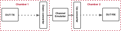
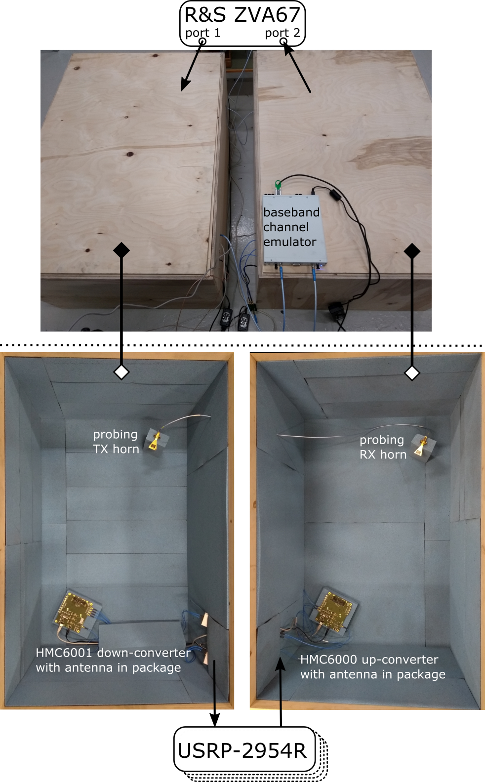
Fig. 1 depicts the main idea behind the OTA system for testing equipments against replicated channels: a DUT transmits its signal in the first anechoic chamber, where a down-converter shifts the OTA transmitted signal to baseband. Then, a baseband emulator convolves the baseband signal with a (baseband) representation of the channel. Finally, in a second chamber, the baseband signal is up-converted and transmitted to another DUT in receive mode. In this initial study, we replaced the DUTs with the vector-network analyser R&S ZVA67. Our set-up is illustrated in Fig. 2.
Ideally, the whole down-conversion and up-conversion would be transparent as if a cable was used to connect the baseband ports and the set-up would be frequency flat.
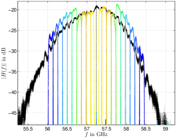
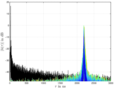
The measured TF of two-chamber set-up connected through a cable is shown in black in Fig. 3. The frequency selectivity stems from the selectivity of the employed converters (HMC6000, HMC6001). Details of the chip-set used as RF frontend can be found in [18]. There is a ripple observed due to small reflections at connectors and baseband components and a pass-band behaviour resultant from the limited usable bandwidth of the converters. The measured TF is converted into the delay domain via the inverse discrete Fourier transform, see Fig. 4. The obtained channel impulse response (CIR) shows the desired spike-like shape with almost negligible initial delay. We hence conclude that the assembled anechoic chambers together with the utilized converters act as almost ideal one-tap channel, already without equalization.
Next, we inserted an SDR, namely, National Instruments (NI) USRP-2954R and emulated a single tap channel with of bandwidth between the TX and RX chambers. We examined spectral stitching [19, 20] by shifting the center of operation of the USRP by at a time, and laying the acquired TFs side by side. It is observed that a small fraction of the possible bandwidth is cut out, due to the RF frontend of the USRP.
The stitched sub-channels follow the frequency selectivity of the OTA set-up (chamber and up/down converters) and introduce no further selectivity, as shown in Fig. 3. At approximately MHz the USRP changes the front-end, resulting in a higher gain. This behaviour together with the overall frequency shape (low-pass shape) requires an equalizer when several USRPs operate on parallel sub-bands. However, a simple one-tap equalizer (adapting the gain and the initial delay) suffices to obtain an almost frequency flat characteristic before channel emulation, see Fig. 5 and Fig. 6.
III Emulated Channels
The emulator has been implemented by running a custom design code on a NI USRP 2954-R SDR platform. The code is based on the work reported in [1] with modification to support the higher bandwidth of operation namely, . The emulator implements a tapped delay line with 10 simultaneously active taps. The delay, and complex amplitude of each tap are updated for every channel snapshot in order to enable emulation of non-stationary channels. This allows us to aim for accurately replicating driving scenarios in which the channel dynamics change at a very fast rate.
III-A Two-Tap Channel
To verify that our SDR emulation is running properly, we emulate a simple two-tap channel [10] with equal gain for each tap, given as
| (1) |
III-B Reproducing a Measured Channel
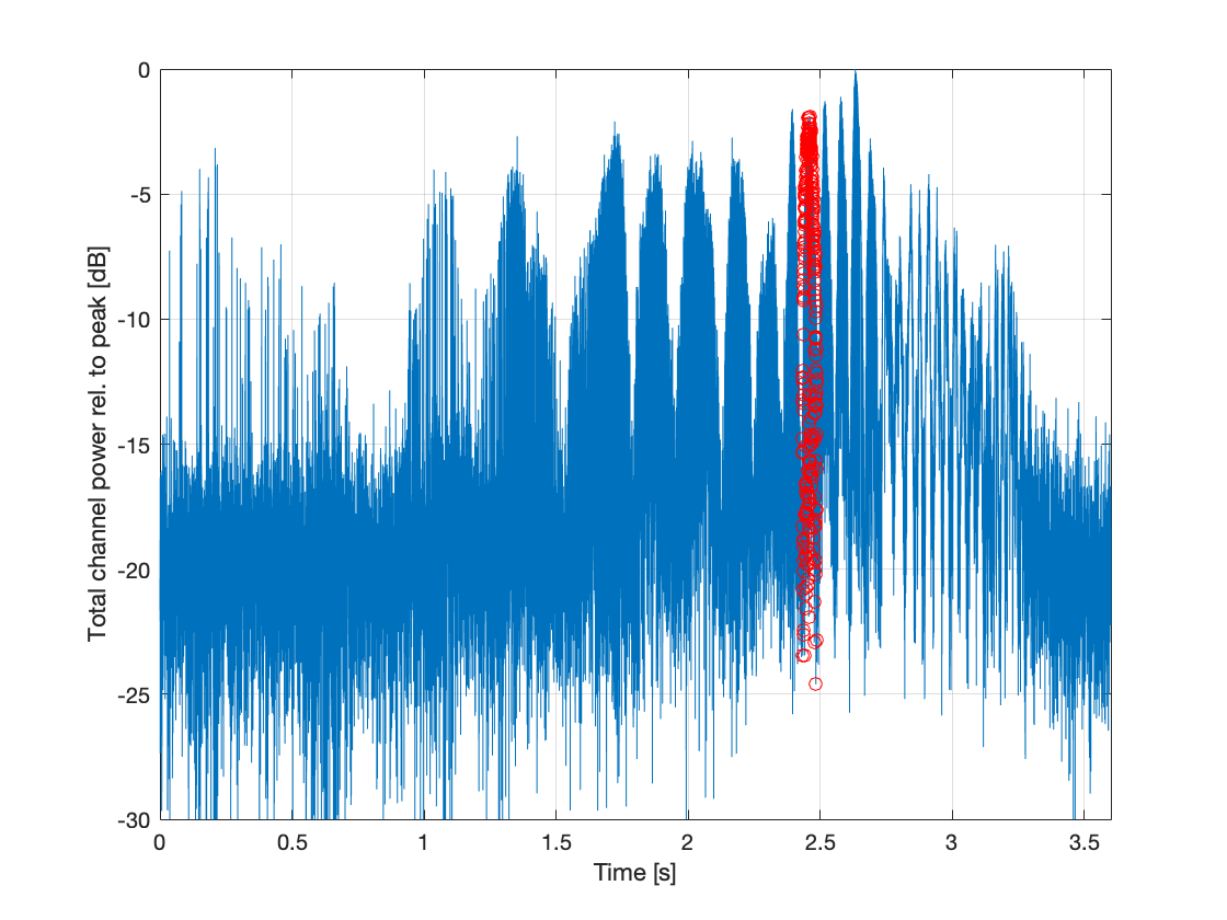
In this section, we demonstrate reproduction of a time-variant channel by “play-back” of the measurement campaign published in [5]. The measured scenario is V-band vehicle-to-infrastructure communications with a directive transmit antenna and an omni-directional receive antenna. A vehicle drives towards a street crossing at a speed close to in an urban street canyon, while transmitting at GHz with a bandwidth of MHz with an horn antenna on the roof top directed in direction of driving. The receiver is positioned directly at the crossing at m elevation. For this scenario, the received signal experiences distinct Doppler shifts between paths from the line-of-sight (LOS), the ground reflection, and multiple scatterers. In [5], it has been shown that this channel is very sparse in the delay-Doppler domain, hence, the channel is approximated with active taps at a time. The approximation follows the strategies proposed in [21, 22, 23, 14]. As seen in [5], the channel fluctuates semi-deterministically with the position. For the initial analysis to evaluate the emulator, we were interested in a section of the measurement that provided high signal-to-noise ratio (SNR). Hence, we focus on a section containing a total number of 301 snapshots starting at the s mark for the duration of , as shown in Fig. 9 by red marks.
As the measurements were conducted with MHz bandwidth, a direct emulation with a single USRP 2954-R is possible. The time-variant TF, its time-variant CIR, and its delay-Doppler spreading function are shown in Figs. 10 – 12, respectively. The respective formulas are found in [24].
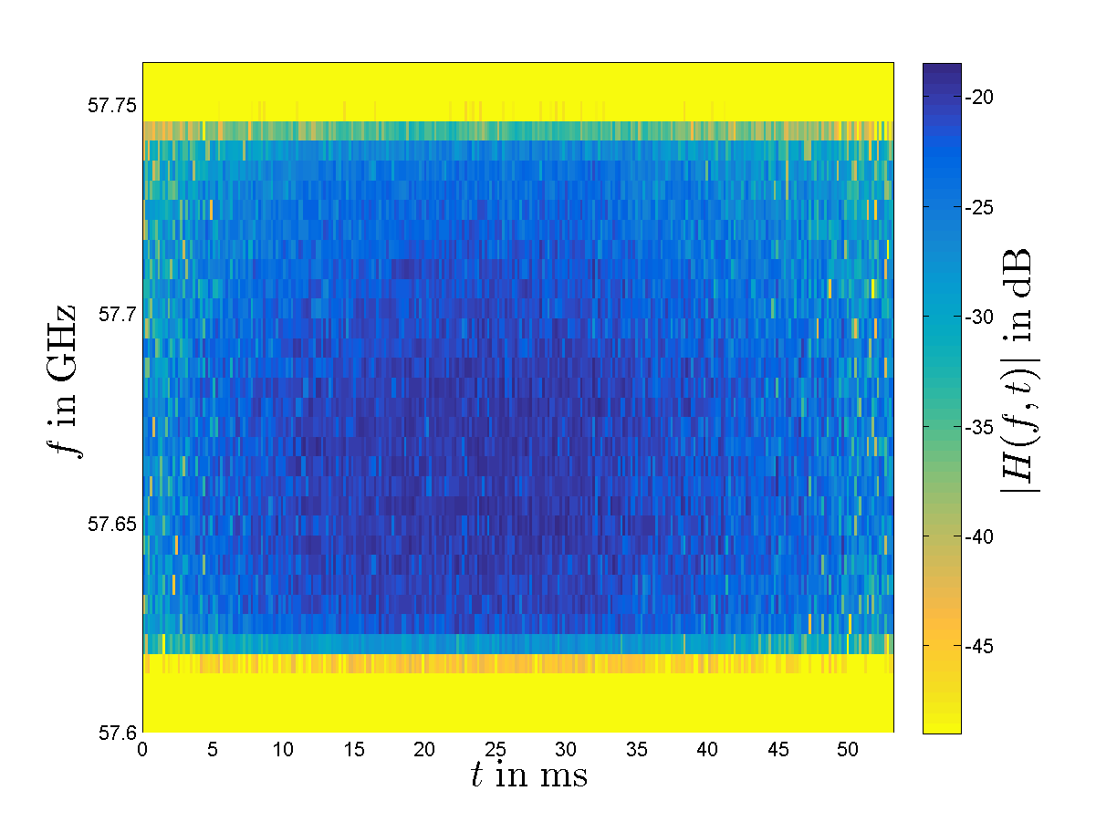
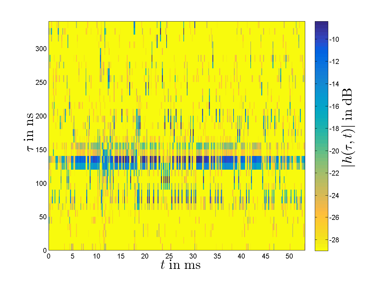
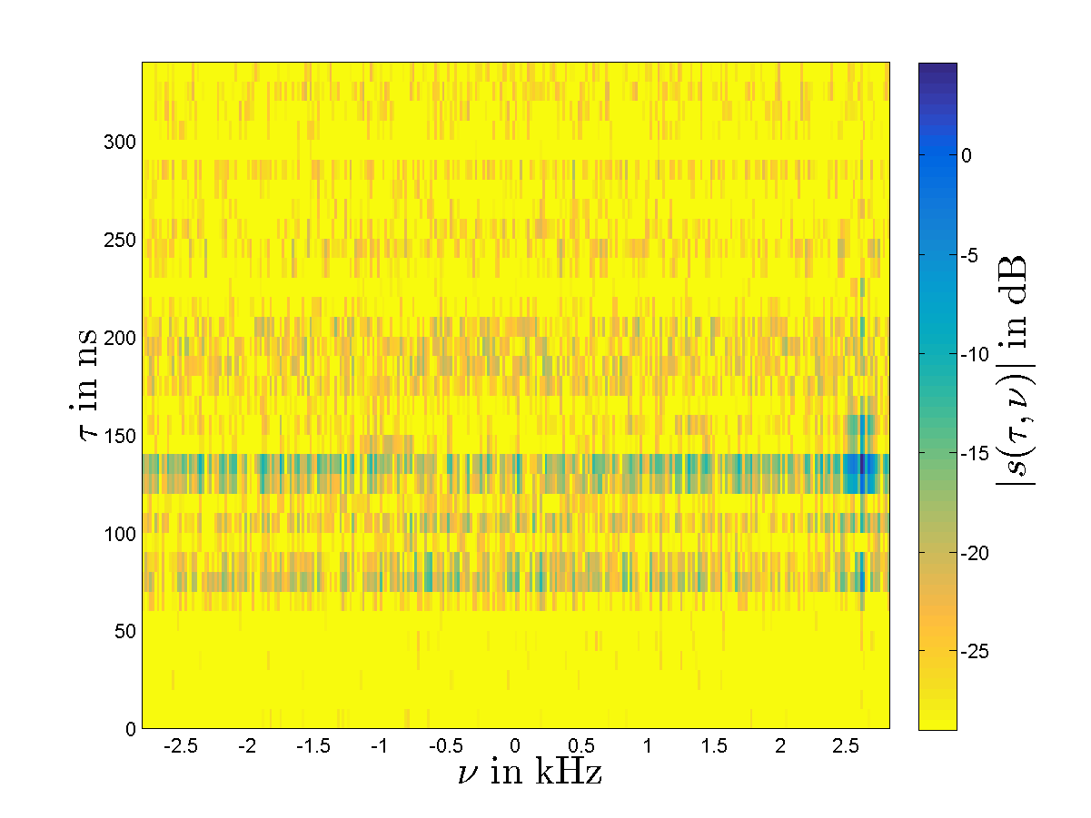
Due to the relatively narrow bandwidth of MHz, the time-variant frequency response does not show many notches in magnitude and appears relatively flat. The time-variant CIR is hence dominated by the LOS. Eventually, the delay-Doppler plane shows the dominant LOS component at approximately kHz as shown in Fig. 12. The fades of the LOS component are due to the street reflections which appear at the same delay tap. The other fluctuations in either domain are due to noise originating from fitting of the channel to emulate and due to the non-ideal characteristics of the emulator.
IV Conclusion
This contribution shows a custom built millimetre wave over-the-air testing system with low complexity. We show that our system is almost frequency flat and that multiband processing via several USRPs is feasible. The wideband emulation only needs a one-tap equalization and appropriate channel representations at all subbands. A mathematical formulation for selecting the channel taps at different sub-bands is already achieved [15, 2].
Acknowledgment
The authors would like to thank Christoph Friedrich Mecklenbräuker and Nils Torbjörn Ekman for their insightful discussions. They are also grateful to Connectivity Technologies and Platforms department at Sintef Digital and ReRaNP lab at NTNU for facilitating parts of the equipments. Special thanks goes to IES department at NTNU and IRACON COST action for their support to this project.
References
- [1] G. Ghiaasi, T. Blazek, M. Ashury, R. R. Santos, and C. Mecklenbräuker, “Real-time emulation of nonstationary channels in safety-relevant vehicular scenarios,” Wireless Communications and Mobile Computing, vol. 2018, no. 2423837, pp. 1–11, 2018.
- [2] T. Blazek, E. Zöchmann, and C. Mecklenbräuker, “Millimeter wave vehicular channel emulation: A framework for balancing complexity and accuracy,” Sensors, vol. 18, no. 11, p. 3997, 2018.
- [3] W. Roh, J.-Y. Seol, J. Park, B. Lee, J. Lee, Y. Kim, J. Cho, K. Cheun, and F. Aryanfar, “Millimeter-wave beamforming as an enabling technology for 5G cellular communications: Theoretical feasibility and prototype results,” IEEE Communications Magazine, vol. 52, no. 2, pp. 106–113, 2014.
- [4] E. Zöchmann et al., “Measured delay and Doppler profiles of overtaking vehicles at 60 GHz,” in Proc. of 12th European Conference on Antennas and Propagation (EuCAP), 2018.
- [5] H. Groll et al., “Sparsity in the delay-Doppler domain for measured 60 GHz vehicle-to-infrastructure communication channels,” in Proc. of IEEE International Conference on Communications Workshops (ICC Workshops), 2019.
- [6] J.-J. Park, J. Lee, K.-W. Kim, M.-D. Kim, and K. C. Lee, “Multipath propagation characteristics for 5G vehicular communications based on 28 GHz expressway measurements,” in Proc. of 13th European Conference on Antennas and Propagation (EuCAP), 2019.
- [7] ——, “28 GHz Doppler measurements in high-speed expressway environments,” in Proc. of IEEE 29th Annual International Symposium on Personal, Indoor and Mobile Radio Communications (PIMRC), 2018.
- [8] H. Wang, X. Yin, X. Cai, H. Wang, Z. Yu, and J. Lee, “Fading characterization of 73 GHz millimeter-wave V2V channel based on real measurements,” in Proc.of International Workshop on Communication Technologies for Vehicles. Springer, 2018.
- [9] M. Boban et al., “Multi-band vehicle-to-vehicle channel characterization in the presence of vehicle blockage,” IEEE Access, vol. 7, pp. 9724–9735, 2019.
- [10] E. Zöchmann, K. Guan, and M. Rupp, “Two-ray models in mmWave communications,” in Proc. of IEEE 18th International Workshop on Signal Processing Advances in Wireless Communications (SPAWC). IEEE, 2017.
- [11] E. Zöchmann et al., “Statistical evaluation of delay and Doppler spread in 60 GHz vehicle-to-vehicle channels during overtaking,” in Proc. of the IEEE-APS Topical Conference on Antennas and Propagation in Wireless Communications (APWC), 2018.
- [12] E. Zöchmann et al., “Position-specific statistics of 60 GHz vehicular channels during overtaking,” IEEE Access, vol. 7, pp. 14 216–14 232, 2019.
- [13] E. Zöchmann, J. Blumenstein, R. Marsalek, M. Rupp, and K. Guan, “Parsimonious channel models for millimeter wave railway communications,” in Proc. of IEEE Wireless Communications and Networking Conference (WCNC), 2019.
- [14] T. Blazek, E. Zöchmann, and C. F. Mecklenbräuker, “Model order selection for LASSO fitted millimeter wave vehicular channel data,” in Proc. of IEEE 29th Annual International Symposium on Personal, Indoor and Mobile Radio Communications (PIMRC). IEEE, 2018.
- [15] ——, “Approximating clustered millimeter wave vehicular channels by sparse subband fitting,” in Proc. of IEEE 29th Annual International Symposium on Personal, Indoor and Mobile Radio Communications (PIMRC). IEEE, 2018.
- [16] Y. P. Zhang and D. Liu, “Antenna-on-chip and antenna-in-package solutions to highly integrated millimeter-wave devices for wireless communications,” IEEE Transactions on Antennas and Propagation, vol. 57, no. 10, pp. 2830–2841, 2009.
- [17] W. Fan, P. Kyosti, M. Rumney, X. Chen, and G. F. Pedersen, “Over-the-air radiated testing of millimeter-wave beam-steerable devices in a cost-effective measurement setup,” IEEE Communications Magazine, vol. 56, no. 7, pp. 64–71, 2018.
- [18] P. Zetterberg and R. Fardi, “Open source SDR frontend and measurements for 60-GHz wireless experimentation,” IEEE Access, vol. 3, pp. 445–456, 2015.
- [19] K. Shi, E. Sillekens, and B. C. Thomsen, “246 GHz digitally stitched coherent receiver,” in Optical Fiber Communication Conference. Optical Society of America, 2017.
- [20] S. L. Dark, D. J. Baker, and J. R. Ammerman, “Spectral stitching method to increase instantaneous bandwidth in vector signal analyzers,” 2016, US Patent 9,326,174.
- [21] C. F. Mecklenbräuker, P. Gerstoft, and E. Zöchmann, “c–LASSO and its dual for sparse signal estimation from array data,” Signal Processing, vol. 130, pp. 204–216, 2017.
- [22] T. Blazek and C. F. Mecklenbräuker, “Sparse time-variant impulse response estimation for vehicular channels using the c-LASSO,” in 2017 IEEE 28th Annual International Symposium on Personal, Indoor, and Mobile Radio Communications (PIMRC). IEEE, 2017.
- [23] E. Zöchmann, P. Gerstoft, and C. F. Mecklenbräuker, “Density evolution of sparse source signals,” in Proc. of 3rd International Workshop on Compressed Sensing Theory and its Applications to Radar, Sonar and Remote Sensing (CoSeRa). IEEE, 2015.
- [24] A. F. Molisch, Wireless communications. John Wiley & Sons, 2012, vol. 34.