,
Towards Occlusion-Aware Multifocal Displays
Abstract.
The human visual system uses numerous cues for depth perception, including disparity, accommodation, motion parallax and occlusion. It is incumbent upon virtual-reality displays to satisfy these cues to provide an immersive user experience. Multifocal displays, one of the classic approaches to satisfy the accommodation cue, place virtual content at multiple focal planes, each at a different depth. However, the content on focal planes close to the eye do not occlude those farther away; this deteriorates the occlusion cue as well as reduces contrast at depth discontinuities due to leakage of the defocus blur. This paper enables occlusion-aware multifocal displays using a novel ConeTilt operator that provides an additional degree of freedom — tilting the light cone emitted at each pixel of the display panel. We show that, for scenes with relatively simple occlusion configurations, tilting the light cones provides the same effect as physical occlusion. We demonstrate that ConeTilt can be easily implemented by a phase-only spatial light modulator. Using a lab prototype, we show results that demonstrate the presence of occlusion cues and the increased contrast of the display at depth edges.

1. Introduction
The primary aim of a virtual-reality (VR) display is to present a scene to the eye that is indistinguishable from reality. In the context of depth perception, a VR display has to faithfully reproduce the visual cues pertaining to disparity, accommodation, occlusion, and motion parallax. While there are many types of VR displays, each with differing amounts of fidelity towards satisfying these cues, this paper focuses on multifocal displays with the objective of enhancing the range of perceptual cues that they can satisfy.
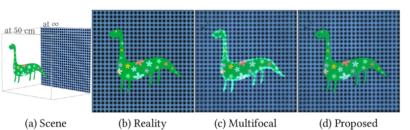
In a multifocal display, three-dimensional (3D) content is shown to a user by placing virtual objects on different focal planes, which are optically placed at different depths from the viewer. This has a unique advantage that the display automatically renders the accommodation cues, i.e., supports the focus of our eyes, provided there are a sufficient number of focal planes (Rolland et al., 1999; MacKenzie et al., 2010; Watt et al., 2012; Chang et al., 2018). In order to display multiple focal planes at different depths, the focal planes are time-multiplexed and content on the planes does not occlude each other. Hence, the focal planes behave as if they were transparent, as seen in Fig. 1b. This inability to occluded light leads to two adverse effects. First, the display is incapable of satisfying occlusion cues since even small displacements of the eye will readily produce overlapping contents. Second, even when the eye is positioned correctly, the contrast of depth edges is greatly reduced. This can be seen from the example shown in Fig. 2c; when our eyes focus on the dinosaur and the far focal planes get defocused, the defocused background bleeds into the dinosaur and reduces its contrast. Both of these effects reduce the immersive nature of the VR experience.
One potential approach for enabling occlusion cues on a multifocal display is to use a light-field display. The improved angular resolution allows us to control the intensity of the light rays that a pixel sends in different directions. The occlusion cue can then be produced by avoiding sending light through any virtual opaque object on the front focal planes. However, the additional angular resolution usually comes at the cost of significant loss in spatial resolution (Lanman and Luebke, 2013; Huang et al., 2015). The loss of contrast at depth edges can also potentially be addressed by optimizing the content shown on focal planes to account for the transparency (Narain et al., 2015; Padmanaban et al., 2017). However, such optimization is tuned to a specific view point and the visual immersion breaks down when the viewpoint is shifted even slightly.
This paper provides a design for multifocal displays, capable of rendering occlusion cues, without any loss of spatial resolution. Our key idea is that to satisfy occlusion cues, for most scenes we do not need real angular resolution in the physical display, but simply the ability to tilt the light cone emitted by display pixels. With appropriate tilts of the light cones, we can emulate the same effect as physical occlusion between real objects.
Fig. 1c illustrates the case when we try to partially occlude a pixel on a far focal plane. For pixels on the far focal plane, since the occluder is on the left, tilting the light cone emitted by the pixel to the right will ensure that no light rays from the pixel pass through the occluder and thereby creates an illusion that the front occluder blocks light. As a result, the near content successfully occludes far content; this is seen in the occlusion of the back content in Fig. 1d as well as realistic defocus blur at depth edges in Fig. 2d. More importantly, since the entire light cone is tilted, we do not need additional angular resolution on the display panel and there is no loss of the spatial resolution of the display.
The tilt of the light cones emitted by display pixels is implemented by placing a phase-only spatial light modulator (phase SLM) on the display panel. By programming the slope of the phase function at each display pixel, we can steer the light cone emitted by each pixel. The phase SLM acts as a freeform field lens that dynamically tilts each light cone based on the virtual scene.
1.1. Contributions
We make the following contributions.
-
•
ConeTilt multifocal displays. Our primary contribution is the use of the ConeTilt operation to endow occlusion cues in multifocal displays without loss of spatial resolution.
-
•
Implementation. We provide a simple approach for implementing ConeTilt using phase SLMs. Given a virtual scene to be displayed, we derive the phase function operating the SLM.
-
•
Design space analysis. We derive important properties of the ConeTilt display including the fidelity of its occlusion cues, the contrast of the display, as well as the field-of-view and the size of the eye box.
-
•
Prototype. We build a lab prototype using off-the-shelf components and demonstrate a ConeTilt display in practice.
1.2. Limitations
The proposed approach comes with the following limitations.
-
•
Dark halo. The ConeTilt operation is not completely equivalent to the cropped light cones achieved by physical occluders; this results in some dark halo artifacts next to depth discontinuities.
-
•
Complexity of the occluding contours. While tilting the cone is sufficient for simple occlusion boundaries, it is insufficient for more complex dense occlusions. Examples include the occluding object being a mesh or dense foliage.
-
•
Limitation of the prototype. Our prototype uses a phase SLM to implement the ConeTilt operation and, as such, we are limited by its ability to tilt light cones. Our prototype uses a phase SLM with m pixel pitch, which can tilt the light cones up to in each direction and this places additional restrictions on our prototype.
We discuss these limitations in detail in Sec. 7.
2. Prior Work
We briefly discuss related research on occlusion cues in VR displays.
2.1. Role of Occlusion in Visual Perception
Among the cues deployed by the human visual system to perceive the world, occlusion plays a dominant role (Cutting and Vishton, 1995; Geng, 2013). When two opaque objects are at different depths, the object in front will occlude some light rays from the object behind. Moving our head and changing our perspective, even by a small amount, will reveal parts of the back object that was originally hidden. The occluding and revealing of objects allows us to easily discover their relative depths even when the objects are in close proximity. Further, when our eye focuses on objects at different depths, the subtle differences in the defocus blur at depth discontinuities are often sufficient to resolve their relative ordering (Zannoli et al., 2016). This makes occlusion one of the dominant cues for depth perception that works reliably across a wide depth range (Cutting and Vishton, 1995). As a consequence, it is of utmost importance that 3D displays, such as VR displays, generate occlusion cues properly.
2.2. Enabling Occlusion Cues in VR Displays
Most commercial VR displays generate occlusion cues by tracking the head/eye and regenerating content from the new perspective. This ensures that occlusion cues are faithfully produced and is only limited by the refresh rate of the display. However, as is often the case, the content is shown on a single plane and hence, there are gross accommodation errors. To alleviate the problem, gaze trackers can be used to estimate the user’s gaze and pupil position, and subsequently update the displayed content. This increases both the hardware requirement and the computational cost. We instead focus on enabling displays that simultaneously produce the accommodation and the occlusion cues under changing focus and movements of the eyes.
There are many display technologies that can produce occlusion cues without tracking. Cossairt et al. [(2007)] and Jones et al. [(2007)] produce volumetric displays by rotating an anisotropic diffuser in synchrony with a projector. As the diffuser spins, the projector displays an image to be seen by a viewer in a specific direction. This results in realizing occlusion without knowing the position of the viewer. However, the spinning diffuser makes the displays more geared towards 3D televisions and not VR.
Light field displays (Lanman and Luebke, 2013; Huang et al., 2014) provide angular control and, in principle, this is sufficient to produce rich occlusion cues. However, the gain in angular resolution is invariably accompanied by a loss in spatial resolution of the display. Further, the finite pixel pitch of the display greatly limits the depth range the displays can support, i.e., only content whose depth is in the vicinity of the display depth can be faithfully rendered. While there are alternate implementations of light field displays that do not rely on microlens arrays (Huang et al., 2015; Wetzstein et al., 2011), these do share the same challenges in obtaining a large depth range. In comparison, the depth range of multifocal displays is determined by the focus tunable lens and is often more than several diopters.
The importance of occlusion cues and methods to achieve it have been studied extensively in the context of augmented reality (AR) displays (Kiyokawa et al., 2000; Mulder, 2005; Inami et al., 2000; Rathinavel et al., 2019). However, these approaches concentrate on blocking light from real objects, wherein the challenges are different from those in VR displays.
2.3. Multifocal Displays
Multifocal displays (Akeley, 2004) show content at multiple focal planes placed at different depths from the viewer. The displays are capable of producing natural accommodation cues over a wide depth range (Koulieris et al., 2017). There are many possible ways of implementing such a display including using a focus-tunable lens (Liu et al., 2008; Liu and Hua, 2009; Love et al., 2009; Llull et al., 2015; Johnson et al., 2016; Konrad et al., 2016; Rathinavel et al., 2018; Chang et al., 2018; Lee et al., 2019; Jo et al., 2019), a waveplate lens (Tabiryan et al., 2015), or variable-focus Moiré lenses (Bernet and Ritsch-Marte, 2008). Despite the wide varieties in the implementations, the content on different focal planes do not occlude each other and hence, the displays produce inconsistent occlusion and defocus cues at depth discontinuities. Please refer to (Koulieris et al., 2019) for a recent survey on other AR/VR displays.
2.4. Other Related Methods
Phase SLMs have been used in many other works to manipulate light. For example, Matsuda et al. (2017) use a phase SLM to create smooth focal surfaces to support natural vision accommodation in virtual-reality displays. Maimone et al. (2017) create hologram for virtual/augmented reality displays. Levin et al. (2016) use two phase SLMs to create a passive viewpoint-sensitive display. Damberg et al. (2016) create goal-based caustics with a phase SLM to increase the contrast of a high-dynamic-range projector. Note that our use of a phase SLM — attaching it directly on the display panel to create a freeform field lens — is different from all the aforementioned works. This enables us to tilt the light cones while retaining the spatial resolution of the display.
3. ConeTilt Multifocal Displays
We start by studying the occlusion cues in the real world and what happens in its absence in a multifocal display. Subsequently, we introduce the concept of ConeTilt for producing occlusion cues.
3.1. Occlusion Cues in Real Scenes
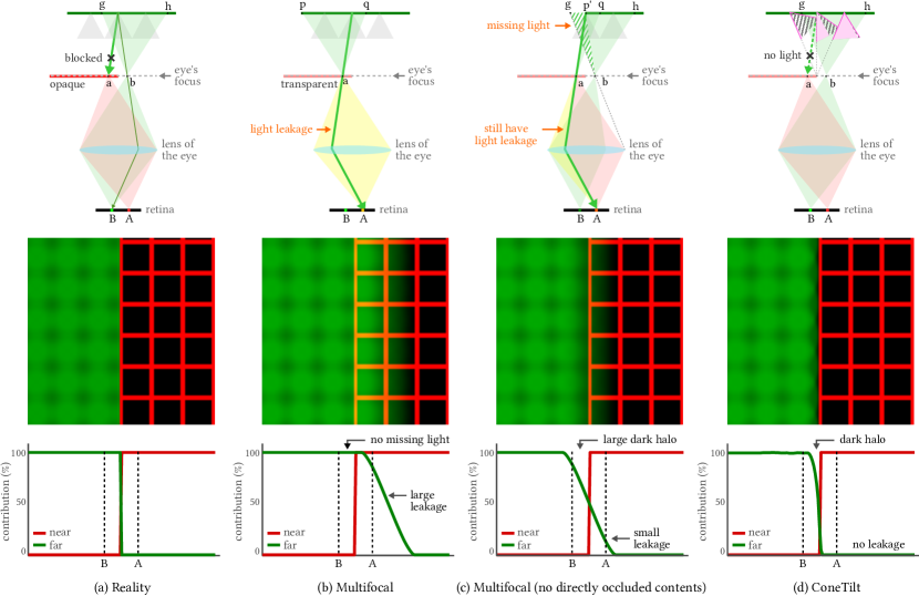
Consider a scene consisting of two fronto-parallel planes, that are opaque and placed at different depths, as shown in Fig. 3a. The front plane is red and the back plane is green; the camera/eye focuses on the front plane. Consider two points and , that are on either side of a depth discontinuity. At point , all the light coming from the back plane is blocked, due to the opaqueness of the front plane. At point , we get light from region on the back plane. Since the camera focuses on the front plane, light passing through point and will be collected by pixel and , respectively. Since no green light from the back object passes through , pixel is pure red.
3.2. Occlusion Cues in Multifocal Displays
Let us now consider the same scene, but rendered by a multifocal display. For simplicity, we will assume that the two planes are displayed on focal planes corresponding to their true depth. As with most multifocal designs, the focal planes are transparent, and as a result, light from the back focal plane can leak through the content shown on the front focal plane. In Fig. 3b, pixel receives not only light emitted by point but also all the light from passing through , making a yellow pixel (instead of red).
The light leakage has two consequences.
-
•
Loss of occlusion cue. When two focal planes are in the depth of field of our eye, their contents will overlap even when we want to display an opaque front object.
-
•
Reduced contrast ratio. When we focus on the front plane (and the back focal plane is defocused), the front focal plane will be overlaid with the blurred content from behind and thereby lose its contrast. The low contrast makes displaying dark objects on the front focal plane very difficult.
Removing occluded contents on the back focal plane cannot solve the leakage problem entirely. In Fig. 3c, we remove the region behind the front object given the position of the eye; however, since each display pixel emits light toward a wide range of angles, light from the region still leaks through point and reduces the contrast of pixel . Removing occluded contents has another side effect — it decreases the intensity of defocused content near depth discontinuities. Let us use point as an example. In reality, point receives light from region . Since we remove occluded region , we reduce the amount of light passing through point and thereby make pixel dimmer than the reality.
3.3. Enabling Occlusion Cues via ConeTilt
The proposed display aims to produce occlusion cues on multifocal displays via a simple operation, that we refer to as ConeTilt. This allows for the cone of light emanated at each display pixel to be independently tilted. We discuss the basic idea of ConeTilt here and defer the details of its implementation to Sec. 4.
We consider the same scenario of a scene with two planes rendered by a multifocal display. However, on the back focal plane, we apply a ConeTilt operation at pixels near the occluding edge that is defined as follows: for each pixel, we tilt the cone such that no emitted light ray intersects with the content shown on the front plane. As is to be expected, the resulting tilt is different across locations. Pixels that are occluded by the front focal plane need to be tilted the most, and the amount of tilt gradually reduces when a pixel moves away from the occluding edge, as shown in Fig. 3d.
Despite its simplicity, ConeTilt effectively reduces light leakage across focal planes. Even though point is transparent, ConeTilt ensures that no pixel on the back focal plane emits light toward point , and thereby, we cannot see the far plane when we look at the front object. This effectively creates an illusion that the front object blocks light. In addition, contrast is preserved as no light leaks through the front object. Since entire light cones are tilted, ConeTilt does not require additional angular resolution and in principle can have the same spatial resolution as a typical multifocal display. A side effect of applying the ConeTilt operator is that ConeTilt eliminates some light rays of the back layer that are not blocked in reality. This leads to some dark halo around occlusion boundaries. We will explain this in more details in Sec. 4.4.
4. Design of ConeTilt Displays
In this section, we describe an optical schematic for implementing the ConeTilt operator, as well as derive its content generation rules.
4.1. Optical Schematic
4.1.1. Optical Schematic of standard multi-focal displays
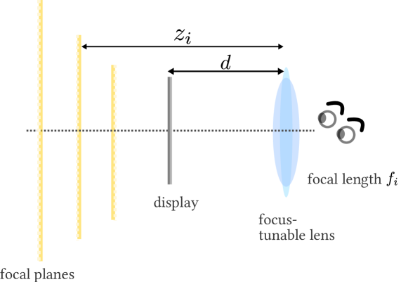
The most popular implementation of a multifocal display uses a focus-tunable lens located at distance in front of a display panel. When the focus-tunable lens has a power corresponding to focal length it generates a virtual copy of the display, or a focal plane, at distance (see Fig. 4) defined by the thin-lens formula
| (1) |
In other words, when the lens has a focal length , the content is presented to the viewer at the depth . To display multifocal focal planes at different depths, the focus-tunable lens and the display cycle through multiple values, displaying content at each focal plane, within the persistence of vision of the human eye. The outcome is that the viewer perceives the superposition of content at all focal planes.
4.1.2. Optical Schematic of the ConeTilt display
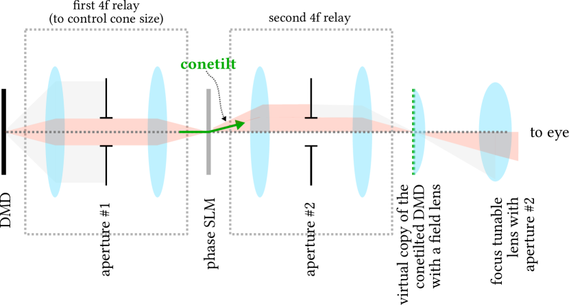
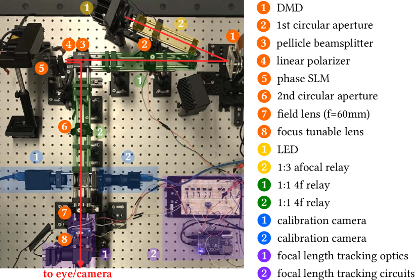
The ConeTilt operation is implemented by optically attaching a phase SLM to the display panel, a digital micromirror device (DMD) in our prototype. This optical setup is illustrated in Fig. 5, which is composed of the DMD, the phase SLM, two one-to-one relays, a field lens, and a focus-tunable lens that serves as the main lens of the multifocal display. The first relay optically colocates the DMD and the phase SLM, and the second relay is used to place a field lens which will be discussed below. We also use the extra spacing introduced by the second relay to place additional calibration cameras (please see the supplemental material for details). Conceptually, as the phase SLM is optically collocated on the DMD, it serves as a free-form field lens and only controls the direction of the light from the DMD without introducing any magnification that will reduce the spatial resolution of the display. The aperture of the first relay ensures a fixed angular cone arriving the SLM from all DMD pixels. Note that we need to crop any tilted light ray whose direction exceeds the angular range of the original light cone. This is achieved with a second aperture that can be placed at the second relay or on the focus tunable lens.
4.2. Deriving the Direction and Magnitude of the Cone Tilt
We now describe our strategy for determining the parameters of the tilt, namely its direction and magnitude, at each pixel. This is illustrated in Fig. 6(a). Suppose that a light cone is occluded (partially) by a virtual object on a front focal plane. The goal of ConeTilt is to ensure that no light rays in the light cone intersects with the occluder. Let the center of the light cone on the front focal plane be . We first identify the point on the occluding contour that is closest to . Then we steer towards (or away from) such that the tilted light cone just touches the occluding contour. As can be seen from Fig. 6(a), using ConeTilt enables the display to approximate the occlusion caused by the virtual object.

4.2.1. Image Formation in ConeTilt Displays.
We derive analytical expressions of the position of the light cone, taking into account the effect of the focus-tunable lens and the vignette of the optics. For simplicity, we assume small-angle (paraxial) scenarios.
Avoiding Vignetting with a Field Lens.
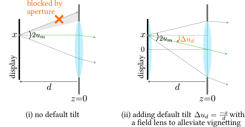
Consider a multifocal display which is composed of a focus-tunable lens and a display panel, as shown in Fig. 6(b)(i). Without any tilt, the light cone from each display pixel travels straight, and part of the cone will be blocked by the aperture of the tunable lens, which causes vignetting.
To avoid vignetting, we place a field lens on the virtual copy of the display to introduce a default tilt so that the entire light cone enters the aperture without being blocked. This default tilt directs the chief ray of the light cone towards the center of the tunable lens, as shown in Fig. 6(b)(ii). It is easy to show that the default tilt, denoted by , reduces to
| (2) |
and this is achieved by choosing the focal length of the field lens to be equal to . This tilt can also be implemented by the phase SLM, but we avoided this due to the limited angular range of the SLM.
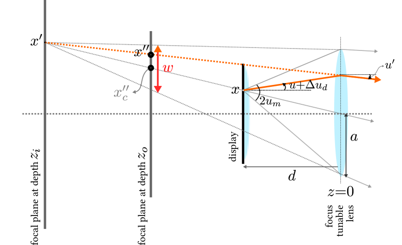
Ray Tracing.
For simplicity, let us first consider a two-dimensional flatland. According to Eq. (1), when the focal-length of the tunable lens is , the pixel on the DMD forms a virtual pixel on the focal plane at depth , where
| (3) |
as illustrated in Fig. 6(c). This means that after the focus-tunable lens, the light ray will intersect the focal plane at depth on with angle , where is the direction of the light ray and is the default tilt. Given the focal length of the tunable lens and Eq. (2), we can calculate by simple ray tracing:
| (4) |
We are interested in the intersection of the light cone on a front focal plane at depth where an occluder lies on. Let the intersection of the light ray on the front focal plane be . By ray tracing, we have
| (5) |
From Eq. (5), we can see that is an affine function of , which has two implications. First, this means that the light cone intersects continuously on the front focal plane, centers at (), and has a diameter of given as
| (6) |
This enables us to calculate whether a light cone is occluded by a virtual front object. Second, when we tilt the light cone emitted by pixel by , the center of the light cone shifts by
| (7) |
This enables us to compute the required tilt to avoid a front occluder. The expressions extend gracefully to 3D scenes by indexing points with , instead of , and angles with instead of .
Calculating ConeTilt Parameters
If a light ray from a back focal plane intersects with a point with content on a front focal plane, we need to design a tilt that will move the cone to the periphery of the content in the front focal plane. Our strategy is illustrated in Fig. 6(a). In particular, if a pixel on the front focal plane is within distance from , the light cone from is occluded, and we need to tilt the cone. To estimate the required amount of the tilt, , we first identify the point on the occluding contour that is closest to ; the direction of the tilt is along the vector . The magnitude of the tilt is determined such that the trailing edge of the cone is incident on and hence, we can identify the point , that represents the center of the light cone after ConeTilt. From Eq. (5), we can calculate the tilt by solving:
| (8) |
We repeat this for all points on each of the focal planes and effectively compute the ConeTilt associated with each displayed pixel. Having derived the desired tilt for each pixel, we now derive the SLM phase function realizing the tilt.
4.3. Deriving the Phase Function
We start by deriving the ideal phase function and account for SLM restrictions later. Let the phase function of the phase SLM be , where , and the wave number be , where is the wavelength of the emitted light, which is assumed to be monochromatic or narrowband. When a light ray reaches the phase SLM at with direction , the phase function delays the wavefront of the light and causes the light ray to change direction. Assuming all angles are small, the outgoing direction can be calculated by
| (9) |
Thereby, our goal is to find a phase function that satisfies , where is the desired tilt of the display pixel at .
We find the phase function by solving a Poisson optimization problem. Let and be the vectorized coordinates of the target tilts of all display pixels, where and are the number of pixels in the and direction, respectively. Let be the discretized phase function that we try to find. We solve the following optimization problem
| (10) |
where and represent taking derivative along and , respectively, and is a small constant used to control the smoothness of the phase function. In all our experiments, we set .
Incorporating Phase SLM Constraints
Due to the discretization, the phase functions that can be displayed on a phase SLM is limited by the Nyquist sampling theorem. To avoid phase aliasing effect, we can only show phase functions that do not have high-frequency variations. The maximum phase difference between two neighboring SLM pixels cannot be more than , leading to
| (11) |
where is the pixel pitch of the SLM pixels along the direction. The same constraint applies to the direction. The constraint (11) limits the maximum angle that we can shift the light cones using the phase SLM.
From Fig. 6(a) we can see that given the radius of a light cone , the maximum amount of tilt that we will need is (when the entire cone goes out of the aperture). Therefore, Eq. (11) sets an upper bound of the radius of the light cone:
| (12) |
By controlling the first aperture in Fig. 5 we can bound the light cone to satisfy Eq. (12). Our phase SLM has a pixel pitch m; when nm, the radius is upper-bounded by degrees. In addition to constraining the size of the aperture used, the limited tilting power of the phase SLM also constrains the eye box of the display, as we will discuss this next.
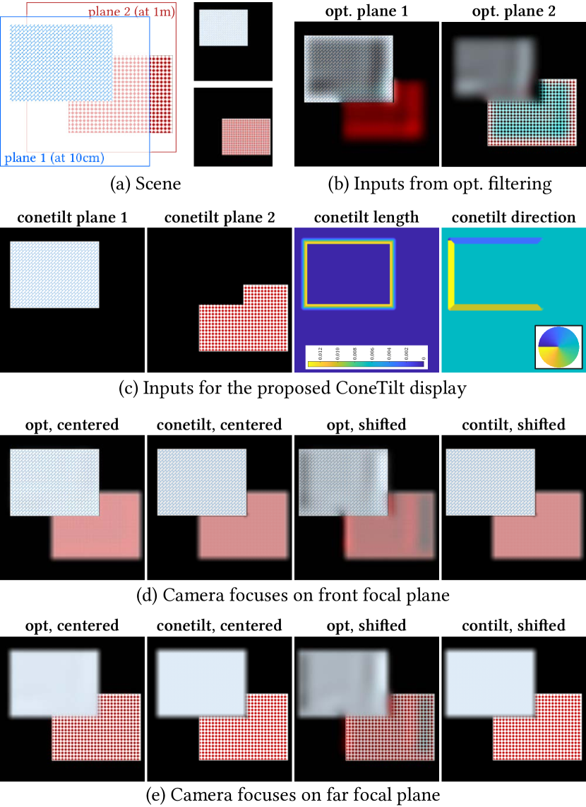
Examples.
Fig. 7 demonstrates some simple scenes composed of two planes at different depths. Given a scene, we find the minimum tilt for each pixel on the back plane to avoid front objects and construct a phase pattern for realizing the tilt. As can be seen from renderings of a camera focused on the front and back focal planes, ConeTilt effectively avoids the light leakage from the back plane.
4.4. Properties of the ConeTilt Display
Dark Halo Near Occluding Edges.
Let us revisit the illustrations shown in Fig. 6a. In a real scene, the light cone emitted by the background point will be cutoff by the occluder such that only the light in the crescentic region can pass. In contrast, a ConeTilt display — which works by tilting a small light cone — can only render the light in the green region, and as a result, some light rays are missing in the virtual scene. The main effect of missing some light rays, as illustrated in Fig. 7, is that the defocused objects near the occluding boundaries are dimmer compared to the reality. Note that by reducing the amount of tilt, we can decrease the dark halo. This provides an interesting trade-off between the light leakage and dark halo and is left as a future work.
Field-of-View
When the eye is close to the tunable lens, the field-of-view of a multifocal display depends on the size of the display panel and the distance . Our prototype, due to its use of a field lens to avoid vignetting, is capable of displaying content on the entire display panel without being constrained by the phase SLM. Hence, its field-of-view is the same as a typical multifocal display of the same design parameters.
Eyebox.
Most multifocal displays have small eye boxes, due to the lack of occlusion cues (which causes virtual objects to overlap when the eye shifts). As a consequence, even though in principle multifocal displays do not require gaze tracking to provide accommodation cues, most implementations use gaze trackers to re-render the scene as the location of the eye changes (Mercier et al., 2017).
In a ConeTilt display, eyes can move freely inside the aperture of the tunable lens without causing overlapping contents. This extends the effective eyebox to the entire aperture without the help of a gaze tracker or re-rendering. In our prototype, the aperture size is only limited by the maximal tilt angle of the phase SLM and is equal to mm in diameter. As stated earlier, the size of the eyebox is primarily determined by the pitch of the phase SLM and using a device with smaller pitch will enhance the size of the eyebox.
Contrast
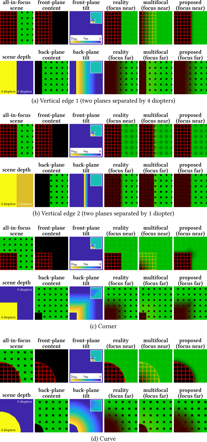
With the ability to prevent light leakage, ConeTilt displays preserve the contrast of focal planes. Fig. 3(b,d) compare the contrast when we display the same content on the focal planes on a typical multifocal display and on a ConeTilt display. As can be seen in the third row, ConeTilt not only reduces the contribution from the back focal plane to the front focal plane, but also makes the transition sharper. Similar trends can be observed in Fig. 7.
4.5. Relationship to Optimization-based Filtering
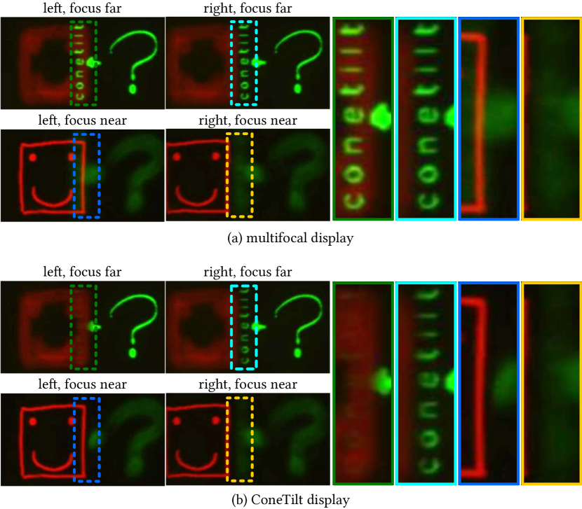
ConeTilt displays can also be interpreted as a hardware counterpart to optimization-based content generation (Akeley et al., 2004; Narain et al., 2015; Mercier et al., 2017; Choi et al., 2019; Xiao et al., 2018) for handling the transparency of focal planes in a multifocal display. Narain et al. (2015) show that leakage of defocus blur at depth discontinuities can be alleviated by optimizing the content shown at the different focal layers. However, since this approach results in a single object being rendered on multiple focal planes, small motion of the eye can lead to inconsistent motion parallax and occlusion cues unless the content is regenerated, using an eye and head tracking system (Mercier et al., 2017). We test the effectiveness of ConeTilt displays and the approach of Narain et al. (2015) in Fig. 8. Even though the optimization-based filtering successfully reproduces the scene when the eye is centered, the quality of the results deteriorates with a slight viewpoint change.
5. Prototype and Experimental Setup
We follow the schematic shown in Fig. 5 and build a prototype ConeTilt display shown in Fig. 9. We use a green LED whose spectrum centers at nm as our light source, and we calibrate the phase SLM to operate at this wavelength. Our prototype implements a light cone of degrees in radius, a field-of-view of degrees in diameter, and an eye box of mm in diameter. Note that since our prototype uses a physical field lens to implement the default tilt, the field of view is the same as a multifocal display of the same configuration. The small field-of-view is due to the simplicity of our implementation and can be increased by moving the tunable lens closer to the phase SLM, i.e., reducing , which is currently mm.
To control the focus tunable lens, we follow the implementation of Chang et al. (2018) and build a focal-length tracking system. Our prototype is capable of displaying up to 40 focal planes, uniformly separated (in diopter) from 0 to 4 diopters. We discuss the implementation details in the supplemental material.
5.1. Display Inputs and Capturing Process
Inputs.
Given a 3D scene, we first discretize the scene according to the depth of the focal planes (in diopters) and assign each point in the scene to its nearest focal plane, as our system has a high depth sampling rate (10 focal planes per diopter), depth discretization introduces minimal errors visually. Given the size of the light cone, we remove all pixels that are completely occluded (not seen along each ray in the cone). We then follow the algorithm described in Sec. 4.2 to compute the tilt for each pixel and the phase function to show with each focal plane.
To evaluate the effectiveness of ConeTilt, we do not apply any depth filtering (e.g., linear or optimization-based filtering) to the content. Nevertheless, for most of the scenes, including Figs. 1, 2, 11, 14, and 8, the focal planes of the display match the depth planes of the content such that a virtual object lies entirely on a focal plane; for this specific scenario, linear depth filtering (Akeley et al., 2004) will have no effect on the input images.
Display process.
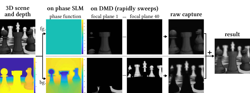
In a straightforward implementation of a multifocal display, one sweeps through the planes, displaying the intensity content of each plane with the DMD and the phase content with the SLM. However, while the refresh rate of the DMD and focus tunable lens are high, the refresh rate of the SLM is limited. To bypass this limitation, we noticed that most scenes can be displayed using only two phase patterns: one pattern displaying the pixels on the foreground (i.e., unoccluded) pixels and one pattern for the background that includes content that is occluded by the foreground for at least one ray via the aperture, namely all the pixels which should be tilted. A single frame of the VR content is, therefore, displayed with two sweeps of the focal tunable lens; in the first sweep, the DMD shows the foreground and the phase SLM pattern is set to zero, and in the second sweep, the background is shown on the DMD with the ConeTilt phase pattern on the SLM. This implies that when the focus tunable lens and DMD display the content of a particular focal plane, the phase tilt associated with all other planes is on as well. However, as no content is shown by the DMD at that part of the frame, the tilt of other focal planes does not contribute to the final image. Figure 10 shows the images displayed on the DMD and SLM during these two cycles, and the images captured by the camera observing them.
Capture process.
We use a FLIR Grasshopper grayscale camera with a Nikkor 35 mm prime lens to capture the photos. We use so that the aperture of the lens lies entirely within the eyebox of our prototype. The camera is put on a linear translation stage in front of the tunable lens to mimic the eye movement. We use a relay to map the camera to the aperture of the tunable lens. This provides ample space for mounting the translation stage and eliminates the magnification due to the unnecessary distance between the camera and the tunable lens. To simplify the synchronization between the DMD and the phase SLM, we capture the foreground and background content separately and sum the two results in post processing, as shown in Fig. 10. To capture each of the foreground and background, we capture and average 10 images, each has a different global phase offset ranging from to (please see Sec. 7.4 for detailed discussion). We use exposure time equal to ms, and the overall capturing process for one grayscale result takes about 20 seconds. Since our prototype is grayscale, to show RGB contents, we display and capture each color channel separately and assemble a three-channel image computationally. Hence, the results shown in the paper are produced artificially to mimic a field sequential display. Note that during the capturing process, the camera is entirely independent of the display, i.e., we do not re-render the scene based on the camera configuration.
6. Results
In the following, we show the results of the ConeTilt display on various scenes designed to highlight the important features of the proposed method. We encourage the reader to check supplemental videos demonstrating translation of viewing position as well as changes of the focal plane.
6.1. Controlling Light Cones with ConeTilt
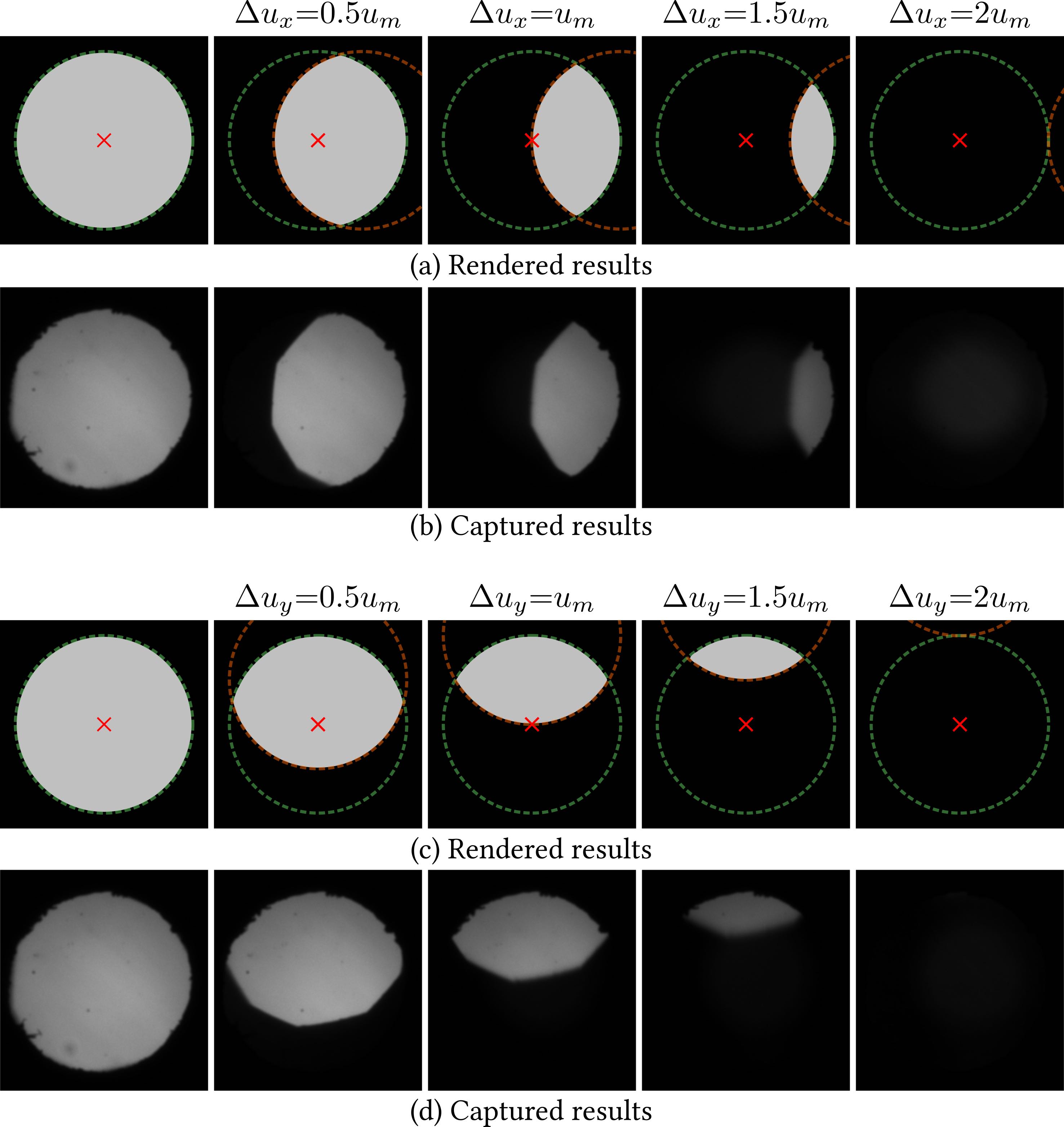
We verify the ability of ConeTilt to tilt light. Fig. 11 shows the light entering the tunable lens under different configurations of tilts. We show a full white image on the DMD and tilt every pixel in the same direction. The results are captured by focusing a camera on the aperture of the tunable lens demonstrating how the light cone is tilting (for details, see the supplemental material).
6.2. Hiding Content Behind Occluders
We demonstrate the capability to hide content behind an occluder and reveal it when the camera/eye shifts — all without re-rendering the scene. The scene in Fig. 1, 12 contains an opaque smiley face in the front and a question mark and the text “conetilt” in the back. We shift the camera with a translation stage from left to right; when the camera is at the left position the text should be occluded by the smiley head, and the text should be revealed when the camera shifts to the right. As can be seen from the results, the smiley face rendered by the typical multifocal display fails to occlude the text and even makes the text brighter due to the additive nature of the front and the back focal planes. In comparison, the text is occluded and revealed when ConeTilt is applied. The lower intensity of the text is as expected, since most of the light rays from the text are occluded by the smiley face, as happens in reality. The results demonstrate the ability of the proposed display to support small shifts of the pupil without the help of a gaze tracker or any additional rendering.
6.3. Generic Occluding Contours
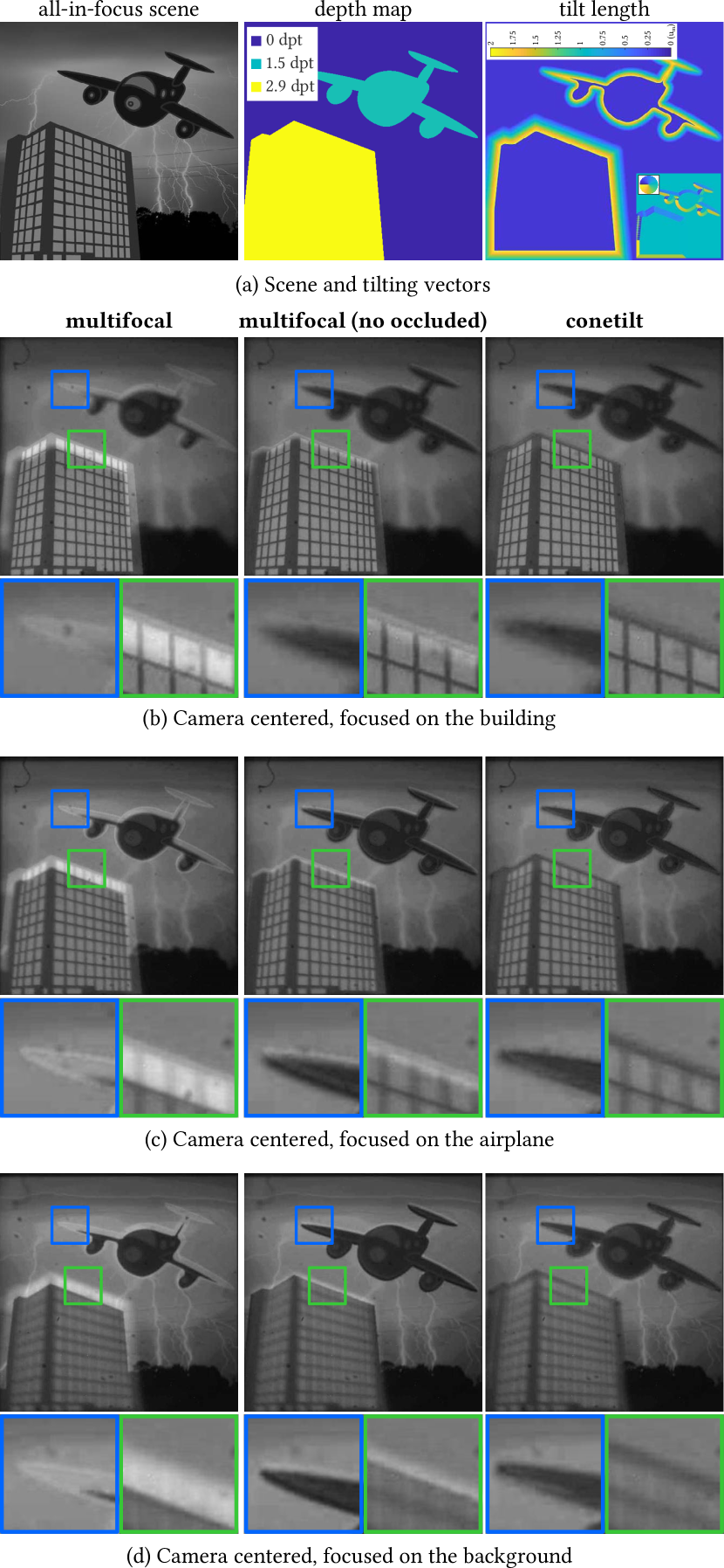
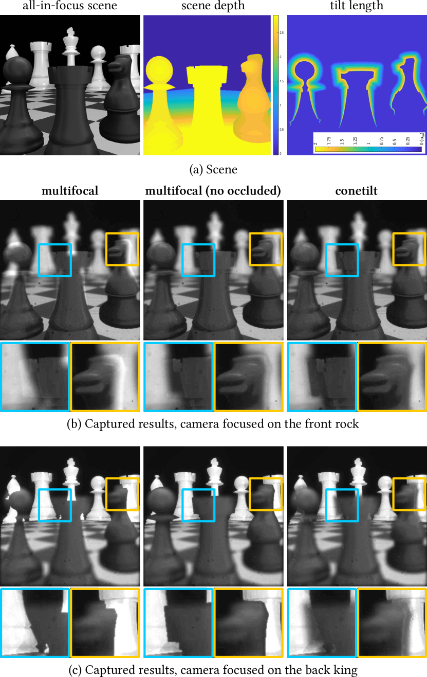
We show captured results on scenes with more complicated occluding contours in Fig. 2 and Fig. 13-16. In Fig. 13 we also compare the captured results against rendering of what one would expect to see in reality. From the results, we can make the following observations.
Reduced Leakage.
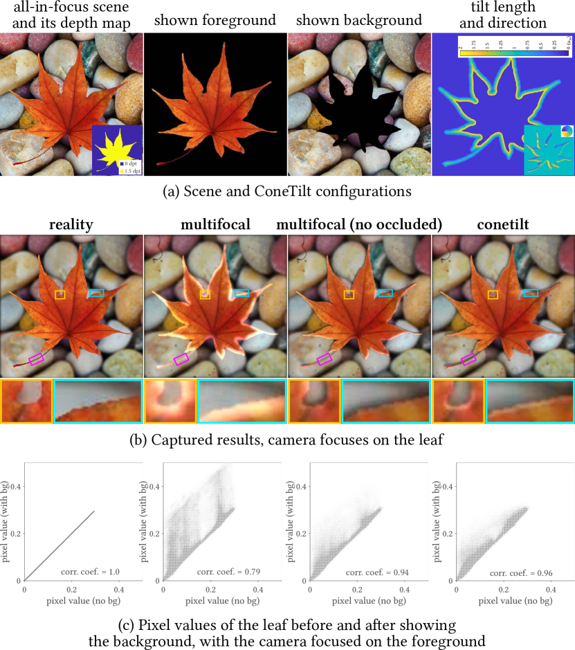
All results consistently demonstrate that the ConeTilt display effectively reduces light leaking from the background onto foreground occluders. Please see the boundaries of the building in Fig. 13a, the top of the rock in Fig. 14b, the boundary of the leaf in Fig. 16b, and the scaffolding structures in Fig. 15b.
While removing the directly occluded regions in the background helps reduce the light leakage in multifocal displays, it only works for a certain viewing position and angle. As can be easily seen from the supplemented videos, when the camera shifts left and right between mm, multifocal displays without directly-occluded content still suffer from light leakage. In addition, removing directly occluded content also worsens the dark halo, as demonstrated in the results and in Fig. 3c.
Improved Contrast.
To quantitatively characterize the effect of ConeTilt on the contrast of the foreground, in Fig. 16 we capture each of the display options twice, once in its standard mode and again when showing a black image at the background plane.
In Fig. 16c we display a scatter plot where the horizontal position of a point corresponds to a grayscale intensity at a foreground pixel of a background-free image, and the vertical position is the intensity of the same pixel when background is displayed. In reality, since the leaf is opaque and is in focus, showing the background should not affect its pixel values, so we would expect the scatter plot to be a diagonal line (). In practice when the background is shown on a multifocal display, light leakage increases the brightness near the depth discontinuities, resulting in pixels with values above the diagonal line and reducing the correlation coefficient. In comparison, the histogram produced by the ConeTilt display is much closer to the diagonal line and has a higher correlation coefficient.

Defocus Cues.
The captured results also demonstrate another advantage of ConeTilt displays over typical multifocal displays. When a multifocal display attempts to reduce light leakages by removing directly occluded content on the background, it deteriorates the defocus cue of the occluder when the camera focuses on the background. As can be seen from Fig. 14c, the defocused foregrounds of the multifocal display (no occluded) look unnaturally sharp even though in reality they should be blurred due to defocus. In comparison, the ConeTilt display successfully renders blurred foregrounds, which is often important for improving the immersion of VR displays (Zannoli et al., 2016).
Dense depth variations.
Quantitative performance.
We quantitatively characterize the performance benefits of the ConeTilt displays. For the dinosaur scene in Fig. 2, over ten rendered images with different viewpoints, we observed an average PSNR of 23.5 dB and SSIM score of 0.967 for a traditional multifocal display, when compared to ground truth renderings. ConeTilt renderings achieved an average PSNR of 31.2 dB and SSIM score of 0.986. The small quantitative difference can be attributed to the depth boundaries being sparse.
7. Discussions
We discuss some of the features of ConeTilt displays, including key limitations and potential ways to mitigate them, as well as approaches to miniaturize our prototype and obtain a form factor suitable for VR glasses.
7.1. Accuracy of Poisson optimization
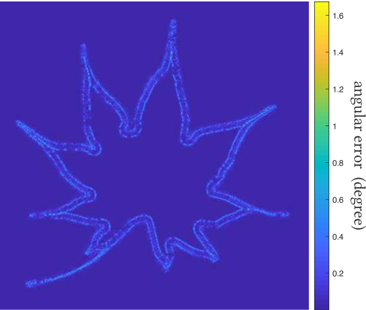
Since the displayed phase pattern is obtained by solving a Poisson optimization problem over the desired field of cone tilts, it is not guaranteed that the phase function would tilt the light cones exactly by the desired amounts. We empirically observe that this error is very small. For example, in Fig. 2, the average angular error over the entire SLM is and is (or of the largest SLM tilting angle) near the occlusion boundaries. Fig. 17 visualizes this error for the scenes in Figs. 2 and 16. As can be seen, the errors are concentrated at the inner-most occluded pixels, where we have large changes in the tilting angles.

7.2. Artifacts
The captured results also shows many of the artifacts in ConeTilt displays. We can see the dark halo in Fig. 14b around the rook and Fig. 16b around the leaf (shown in the blue inset). Note that when removing directly occluded background, the multifocal display also suffers from dark halo. The ConeTilt display also fails to prevent light leakage when two occluding boundaries are too close, as can be seen in Fig. 16b at the narrow breaking of the leaf (yellow inset) and in the railings in Fig. 15c (cyan insets). We point out that there is some light leakage at the tips of leaf and the stem (pink inset). This is due to the smoothness constraint we apply when solving the phase function. For example, pixels at the upper part of the stem need to the tilted upward, whereas the bottom part needs to be tilted downward; this causes the center portion of the stem to be un-tilted. The artifact can be removed by removing these background pixels, at a cost of increasing dark halo.
7.3. Inability to Handle Complex Occlusion Patterns
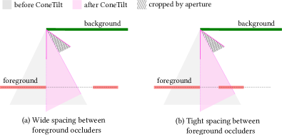
ConeTilt displays tilt entire light cones to mimic the effect of occlusion. While avoiding the loss of spatial resolution, this idea does not extend beyond simple occlusion scenarios where the occluding contours are smooth and well separated. For example, if the front focal plane has two occluding contours in close proximity, as in Fig. 18, ConeTilt would be insufficient to produce the occlusion cue. For such a scenario, we will need to “trim” the light cone, an operation that is beyond the simple tilt operation that we implement.
The minimum distance between two occluding contours on a focal plane is the size of the light cone on the front focal plane. From Eq. (6), we have
| (13) |
where and is the depth of the focal planes, and is the pixel pitch of the display pixels. On our prototype, when the front and the back focal planes are separated by 4 diopters, the minimum distance between two occluders on the front focal plane can be pixels. Note that Eq. (13) decreases quadratically in , whereas the eye box only decreases linearly in . This provides an advantageous trade-off between the minimum distance and the size of the eye box. Specifically, we can allow much closer occluding contours if we are willing to slightly reduce the size of the eye box.
7.4. Limitations Due to the Phase SLM
In addition to the limited capability to tilt light, using a phase SLM induce the following limitations on a ConeTilt display.
Chromatic Aberration.
Since the phase of the light depends on its wavelength, the phase function is color-dependent. To create a typical RGB display, we can use time-multiplexing and show each of the phase functions designed for each color sequentially. To alleviate the chromatic aberration caused by polychromatic light, the phase functions need to be smooth. Thereby, in the optimization problem (10) we use the -regularization to find a smooth solution. Nevertheless, since the phase SLM is attached to the display panel, the chromatic aberrations will only appear in the defocused regions, i.e., on an out-of-focus content that has been tilted.
Phase Wrapping Artifacts.
Since most phase SLMs can only achieve a phase delay of , the phase function will be wrapped multiple times across the entire display. Due to the dramatic change in phase values, the wrapping creates dark seams in the images we see. While using smooth phase functions helps alleviate the problem, in our experience, the most effective solution is to add a global phase offset and rapidly change its value within the exposure time of a frame. Changing the offset shifts the dark seams without affecting the content, thereby it effectively smooths the dark seams.
Diffraction Efficiency.
The limited range of phase delay and the discretization of phase SLMs also results in low diffraction efficiency. When implementing large tilts, the phase functions will be very close to the Nyquist limit. Specifically, the phase functions have large slopes, which, due to phase wrapping, go from to rapidly and repeatedly — much like a grating. This grating-like phase function not only tilts the light cone along the desired direction and angle but also at integer multiples of the desired angle. Thus, the desired angle receives less light. This can be seen in Fig. 11, where the captured image at is dimmer than other images at smaller tilts. We refer to (Laude, 1998) for detailed explanations.
Refresh Rate.
Ideally, each focal plane should be paired with its own phase function. However, typical phase SLMs have a refresh rate of Hz and limits the number of phase functions we can display within a frame. As mentioned earlier in Sec. 5.1, we work around this limitation using a simple decomposition of a scene into a foreground and background, each comprising of a phase functions and its corresponding intensity and depth maps. Nonetheless, a faster SLM would be invaluable in handling complex scene configurations and enabling color displays where each color channel will likely need its own phase patterns tuned to its specific wavelength.
Finally, we note that ConeTilt as an operator need not be implemented on phase SLMs. We can use other technologies that can steer light locally, like the micro-prism proposed by Smith et al. (2006), which enables tilts. This can improve the size of the eye box and the field of view of the display significantly.
7.5. Miniaturization
Practical adoption of ConeTilt displays requires a significant reduction in the footprint of the device. Much of the bulk of our lab prototype is contributed by the off-the-shelf components to build a high-speed display with pixels that emit a light cone of specific angular range. We can, hence, avoid this bulk and achieve a miniaturized prototype by using customized components. Fig. 19 illustrates such a hypothesized design, using the prototype of Matsuda et al. (2017) as a starting point. The key component of this display is an OLED or LCD panel that has a refresh rate sufficiently high enough to display the desired number of depth planes and frame rate. Further, the angular range of light emitted by each pixel needs to be matched to that of the aperture of the eyepiece; in principle, this can be realized during the manufacture process by adding a microlens onto each display pixel, similar to the method used in image sensors. A relay is used to colocate the display panel and the phase SLM, and the same relay is used to redirect light to the eyepiece by the beamsplitter. This design also utilizes customized housings to hold all of the components. Note that by adopting a transparent phase SLM, we can eliminate the need of a beamsplitter and further reduce the bulk of the display.

8. Conclusion
This paper proposes a simple but effective technology for displaying immersive virtual scenes on multifocal displays. The proposed display enables occlusion cues between focal planes of a multifocal display. This has the dual effect of effect of enhancing the range of perceptual cues that the display can satisfy as well as reducing the loss of contrast due to leakage of defocus blur. While our current prototype is bulky and limited by the capability of our phase SLM, the proposed ConeTilt operator can be easily incorporated into existing multifocal displays, while benefiting from the rapidly-evolving light modulation technologies. Hence, we believe that the technology proposed in the paper will spur innovation in virtual and augmented reality systems as well as traditional light-field displays.
Acknowledgements.
The authors acknowledge support via the NSF CAREER grant CCF1652569.References
- (1)
- Akeley (2004) Kurt Akeley. 2004. Achieving Near-correct Focus Cues Using Multiple Image Planes. Ph.D. Dissertation. Stanford University.
- Akeley et al. (2004) Kurt Akeley, Simon J. Watt, Ahna Reza Girshick, and Martin S. Banks. 2004. A Stereo Display Prototype with Multiple Focal Distances. ACM Transactions on Graphics (TOG) 23, 3 (2004), 804–813.
- Bernet and Ritsch-Marte (2008) Stefan Bernet and Monika Ritsch-Marte. 2008. Adjustable Refractive Power From Diffractive Moiré Elements. Applied optics 47, 21 (2008), 3722–3730.
- Chang et al. (2018) Jen-Hao Rick Chang, B. V. K. Vijaya Kumar, and Aswin C. Sankaranarayanan. 2018. Towards Multifocal Displays with Dense Focal Stacks. ACM Transactions on Graphics (TOG) 37, 6 (2018), 198:1–198:13.
- Choi et al. (2019) Suyeon Choi, Seungjae Lee, Youngjin Jo, Dongheon Yoo, Dongyeon Kim, and Byoungho Lee. 2019. Optimal Binary Representation via Non-convex Optimization on Tomographic Displays. Optics Express 27, 17 (2019), 24362–24381.
- Cossairt et al. (2007) Oliver S. Cossairt, Joshua Napoli, Samuel L. Hill, Rick K. Dorval, and Gregg E. Favalora. 2007. Occlusion-capable Multiview Volumetric Three-dimensional Display. Applied Optics 46, 8 (2007), 1244–1250.
- Cutting and Vishton (1995) James E Cutting and Peter M Vishton. 1995. Perceiving Layout and Knowing Distances: The Integration, Relative Potency, and Contextual Use of Different Information About Depth. In Perception of space and motion. 69–117.
- Damberg et al. (2016) Gerwin Damberg, James Gregson, and Wolfgang Heidrich. 2016. High Brightness HDR Projection Using Dynamic Freeform Lensing. ACM Transactions on Graphics (TOG) 35, 3 (2016), 24:1–24:11.
- Geng (2013) Jason Geng. 2013. Three-dimensional Display Technologies. Advances in Optics and Photonics 5, 4 (2013), 456–535.
- Huang et al. (2015) Fu-Chung Huang, Kevin Chen, and Gordon Wetzstein. 2015. The Light Field Stereoscope: Immersive Computer Graphics via Factored Near-eye Light Field Displays with Focus Cues. ACM Transactions on Graphics (TOG) 34, 4 (2015), 60:1–60:12.
- Huang et al. (2014) Fu-Chung Huang, Gordon Wetzstein, Brian A. Barsky, and Ramesh Raskar. 2014. Eyeglasses-free Display: Towards Correcting Visual Aberrations with Computational Light Field Displays. ACM Transactions on Graphics (TOG) 33, 4 (2014), 59:1–59:12.
- Inami et al. (2000) Masahiko Inami, Naoki Kawakami, Dairoku Sekiguchi, Yasuyuki Yanagida, Taro Maeda, and Susumu Tachi. 2000. Visuo-haptic Display Using Head-mounted Projector. In Proceedings of the IEEE Virtual Reality. 233–240.
- Jo et al. (2019) Youngjin Jo, Seungjae Lee, Dongheon Yoo, Suyeon Choi, Dongyeon Kim, and Byoungho Lee. 2019. Tomographic Projector: Large Scale Volumetric Display with Uniform Viewing Experiences. ACM Transactions on Graphics (TOG) 38, 6 (2019), 215:1–215:13.
- Johnson et al. (2016) Paul V Johnson, Jared AQ Parnell, Joohwan Kim, Christopher D Saunter, Gordon D Love, and Martin S Banks. 2016. Dynamic Lens and Monovision 3D Displays to Improve Viewer Comfort. Optics express 24, 11 (2016), 11808–11827.
- Jones et al. (2007) Andrew Jones, Ian McDowall, Hideshi Yamada, Mark Bolas, and Paul Debevec. 2007. Rendering for an Interactive 360∘ Light Field Display. ACM Transactions on Graphics (TOG) 26, 3 (2007).
- Kiyokawa et al. (2000) Kiyoshi Kiyokawa, Yoshinori Kurata, and Hiroyuki Ohno. 2000. An Optical See-through Display for Mutual Occlusion of Real and Virtual Environments. In Proceedings IEEE and ACM International Symposium on Augmented Reality (ISAR 2000). 60–67.
- Konrad et al. (2016) Robert Konrad, Emily A Cooper, and Gordon Wetzstein. 2016. Novel Optical Configurations for Virtual Reality: Evaluating User Preference and Performance with Focus-tunable and Monovision Near-eye Displays. In Conference on Human Factors in Computing Systems (CHI). 1211–1220.
- Koulieris et al. (2019) G. A. Koulieris, K. Akşit, M. Stengel, R. K. Mantiuk, K. Mania, and C. Richardt. 2019. Near-Eye Display and Tracking Technologies for Virtual and Augmented Reality. Computer Graphics Forum 38, 2 (2019), 493–519.
- Koulieris et al. (2017) George-Alex Koulieris, Bee Bui, Martin S. Banks, and George Drettakis. 2017. Accommodation and Comfort in Head-mounted Displays. ACM Transactions on Graphics (TOG) 36, 4 (2017), 87:1–87:11.
- Lanman and Luebke (2013) Douglas Lanman and David Luebke. 2013. Near-eye Light Field Displays. ACM Transactions on Graphics (TOG) 32, 6, Article 220 (Nov. 2013), 10 pages. https://doi.org/10.1145/2508363.2508366
- Laude (1998) Vincent Laude. 1998. Twisted-nematic Liquid-crystal Pixelated Active Lens. Optics Communications 153, 1-3 (1998), 134–152.
- Lee et al. (2019) Seungjae Lee, Youngjin Jo, Dongheon Yoo, Jaebum Cho, Dukho Lee, and Byoungho Lee. 2019. Tomographic Near-eye Displays. Nature communications 10, 1 (2019), 2497.
- Levin et al. (2016) Anat Levin, Haggai Maron, and Michal Yarom. 2016. Passive light and viewpoint sensitive display of 3D content. In IEEE Conference on Computational Photography (ICCP). 1–15.
- Liu et al. (2008) Sheng Liu, Dewen Cheng, and Hong Hua. 2008. An Optical See-through Head Mounted Display with Addressable Focal Planes. In IEEE/ACM International Symposium on Mixed and Augmented Reality. 33–42.
- Liu and Hua (2009) Sheng Liu and Hong Hua. 2009. Time-multiplexed Dual-focal Plane Head-mounted Display with a Liquid Lens. Optics letters 34, 11 (2009), 1642–1644.
- Llull et al. (2015) Patrick Llull, Noah Bedard, Wanmin Wu, Ivana Tosic, Kathrin Berkner, and Nikhil Balram. 2015. Design and Optimization of a Near-eye Multifocal Display System for Augmented Reality. In Imaging and Applied Optics. JTH3A.5.
- Love et al. (2009) Gordon D Love, David M Hoffman, Philip JW Hands, James Gao, Andrew K Kirby, and Martin S Banks. 2009. High-speed Switchable Lens Enables the Development of a Volumetric Stereoscopic Display. Optics express 17, 18 (2009), 15716–15725.
- MacKenzie et al. (2010) Kevin J MacKenzie, David M Hoffman, and Simon J Watt. 2010. Accommodation to Multiple-focal-plane Displays: Implications for Improving Stereoscopic Displays and for Accommodation Control. Journal of vision 10, 8 (2010), 22–22.
- Maimone et al. (2017) Andrew Maimone, Andreas Georgiou, and Joel S. Kollin. 2017. Holographic Near-eye Displays for Virtual and Augmented Reality. ACM Transactions on Graphics (TOG) 36, 4 (2017), 85:1–85:16.
- Matsuda et al. (2017) Nathan Matsuda, Alexander Fix, and Douglas Lanman. 2017. Focal Surface Displays. ACM Transactions on Graphics (TOG) 36, 4 (July 2017), 86:1–86:14.
- Mercier et al. (2017) Olivier Mercier, Yusufu Sulai, Kevin Mackenzie, Marina Zannoli, James Hillis, Derek Nowrouzezahrai, and Douglas Lanman. 2017. Fast Gaze-contingent Optimal Decompositions for Multifocal Displays. ACM Transactions on Graphics (TOG) 36, 6 (2017), 237:1–237:15.
- Mulder (2005) Jurriaan D Mulder. 2005. Realistic Occlusion Effects in Mirror-based Co-located Augmented Reality Systems. In IEEE Proceedings on Virtual Reality. 203–208.
- Narain et al. (2015) Rahul Narain, Rachel A. Albert, Abdullah Bulbul, Gregory J. Ward, Martin S. Banks, and James F. O’Brien. 2015. Optimal Presentation of Imagery with Focus Cues on Multi-plane Displays. ACM Transactions on Graphics (TOG) 34, 4 (2015), 59:1–59:12.
- Padmanaban et al. (2017) Nitish Padmanaban, Robert Konrad, Tal Stramer, Emily A Cooper, and Gordon Wetzstein. 2017. Optimizing Virtual Reality for All Users Through Gaze-contingent and Adaptive Focus Displays. Proceedings of the National Academy of Sciences 114 (2017), 9.
- Rathinavel et al. (2018) Kishore Rathinavel, Hanpeng Wang, Alex Blate, and Henry Fuchs. 2018. An Extended Depth-at-field Volumetric Near-eye Augmented Reality Display. IEEE Transactions on Visualization and Computer Graphics 24, 11 (2018), 2857–2866.
- Rathinavel et al. (2019) Kishore Rathinavel, Gordon Wetzstein, and Henry Fuchs. 2019. Varifocal Occlusion-Capable Optical See-through Augmented Reality Display based on Focus-tunable Optics. IEEE Transactions on Visualization and Computer Graphics 25, 11 (2019), 3125–3134.
- Rolland et al. (1999) Jannick P. Rolland, Myron W. Krueger, and Alexei A. Goon. 1999. Dynamic Focusing in Head-mounted Displays. Proceeding of SPIE 3639 (1999), 3639 – 3639 – 8.
- Smith et al. (2006) Neil R Smith, Don C Abeysinghe, Joseph W Haus, and Jason Heikenfeld. 2006. Agile Wide-angle Beam Steering with Electrowetting Microprisms. Optics Express 14, 14 (2006), 6557–6563.
- Tabiryan et al. (2015) Nelson V Tabiryan, Svetlana V Serak, David E Roberts, Diane M Steeves, and Brian R Kimball. 2015. Thin Waveplate Lenses of Switchable Focal Length-new Generation in Optics. Optics express 23, 20 (2015), 25783–25794.
- Watt et al. (2012) Simon J Watt, Kevin J MacKenzie, and Louise Ryan. 2012. Real-world Stereoscopic Performance in Multiple-focal-plane Displays: How Far Apart Should the Image Planes Be?. In Stereoscopic Displays and Applications XXIII, Vol. 8288. 82881E.
- Wetzstein et al. (2011) Gordon Wetzstein, Douglas Lanman, Wolfgang Heidrich, and Ramesh Raskar. 2011. Layered 3D: Tomographic Image Synthesis for Attenuation-based Light Field and High Dynamic Range Displays. ACM Transactions on Graphics (TOG) 30, 4 (2011), 95:1–95:12.
- Xiao et al. (2018) Lei Xiao, Anton Kaplanyan, Alexander Fix, Matthew Chapman, and Douglas Lanman. 2018. DeepFocus: Learned Image Synthesis for Computational Displays. ACM Transactions on Graphics (TOG) 37, 6 (2018), 200:1–200:13.
- Zannoli et al. (2016) Marina Zannoli, Gordon D Love, Rahul Narain, and Martin S Banks. 2016. Blur and the Perception of Depth at Occlusions. Journal of Vision 16, 6 (2016), 17–17.