Anisotropic Spin-Acoustic Resonance in Silicon Carbide at Room Temperature
Abstract
We report on acoustically driven spin resonances in atomic-scale centers in silicon carbide at room temperature. Specifically, we use a surface acoustic wave cavity to selectively address spin transitions with magnetic quantum number differences of and in the absence of external microwave electromagnetic fields. These spin-acoustic resonances reveal a non-trivial dependence on the static magnetic field orientation, which is attributed to the intrinsic symmetry of the acoustic fields combined with the peculiar properties of a half-integer spin system. We develop a microscopic model of the spin-acoustic interaction, which describes our experimental data without fitting parameters. Furthermore, we predict that traveling surface waves lead to a chiral spin-acoustic resonance, which changes upon magnetic field inversion. These results establish silicon carbide as a highly-promising hybrid platform for on-chip spin-optomechanical quantum control enabling engineered interactions at room temperature.
Hybrid spin-mechanical systems are considered as a promising platform for the implementation of universal quantum transducers Schuetz et al. (2015) and ultra-sensitive quantum sensors Poshakinskiy and Astakhov (2019). Spin states can be coupled by the strain fields of phonons and mechanical vibrations. Coherent sensing of mechanical resonators Kolkowitz et al. (2012), acoustic control of single spins Maity et al. (2020) and electromechanical stabilization of spin color centers Machielse et al. (2019) based on spin-optomechanical coupling have been demonstrated. Similarly to a magnetic field, the application of a static strain field leads to a shift of the spin levels, while a resonantly oscillating strain field induces interlevel spin transitions. Their selection rules are imprinted by the crystal symmetry or device geometry, which provide a high degree of flexibility for on-chip coherent spin manipulation Lee et al. (2017); Satzinger et al. (2018); Takada et al. (2019) and may support chiral spin-phonon coupling Zhu et al. (2018).
Most of the systems coupling atomic-scale spins to vibrations studied so far are based on color centers in diamond MacQuarrie et al. (2013); Arcizet et al. (2011); Kolkowitz et al. (2012); Teissier et al. (2014); Golter et al. (2016); Chen et al. (2019); Machielse et al. (2019); Maity et al. (2020). Two characteristics of silicon carbide (SiC) make it a natural material choice for hybrid spin optomechanics. As diamond, SiC hosts highly-coherent optically-active spin centers, such as negatively charged silicon vacancies () Riedel et al. (2012) and divacancies (VV) Falk et al. (2013). In addition, SiC is already used in commercial nano-electro-mechanical systems (NEMS) with robust performance and ultrahigh sensitivity to vibrations Li et al. (2007). Recently, the mechanical tuning Falk et al. (2014) and acoustic coherent control Whiteley et al. (2019) of the VV spin centers in SiC have been demonstrated at cryogenic temperatures. However, symmetry-dependent spin-acoustic interactions are still largely unexplored and SiC-based hybrid spin-mechanical systems under ambient conditions remain elusive.
In this letter, we demonstrate room-temperature spin-acoustic resonance (SAR) in 4H-SiC. We exploit the intrinsic properties of the half-integer spin system Kraus et al. (2014a), the so-called qudit Soltamov et al. (2019), to realize full control of the spin states using high-frequency vibrations. This is fulfilled by acoustically coupling spin sublevels with magnetic quantum numbers () differing by both and . In contrast to previous SAR studies, which were restricted to atomic-scale spins MacQuarrie et al. (2013); Arcizet et al. (2011); Kolkowitz et al. (2012); Teissier et al. (2014); Golter et al. (2016); Chen et al. (2019); Machielse et al. (2019); Maity et al. (2020); Falk et al. (2014); Whiteley et al. (2019), the spin system enables all-optical readout of the spin state without application of microwave electromagnetic fields. The mechanical vibrations are applied via a surface acoustic wave (SAW) resonator patterned on the 4H-SiC wafer surface perpendicular to the c-axis. The superposition of axial and shear strain components with different amplitudes and phases makes the SARs dependent on the quantization direction of the spin states relative to the SAW propagation direction. Here, this anisotropy manifests itself as a complex angular dependence of the and transitions on the orientation of the external magnetic field applied in the plane perpendicular to the c-axis of 4H-SiC (i.e., with ). We develop a model for spin-3/2 SARs using an effective spin-strain coupling Hamiltonian Poshakinskiy and Astakhov (2019); Udvarhelyi and Gali (2018), which can describe our non-trivial observations. The selective excitation of transitions with and as well as the anisotropic behavior with magnetic field orientation demonstrated here provides extra degrees of freedom for the control of interactions in atomic-scale spin systems.
We present results for the V2 center, corresponding to one of the two possible crystallographic configurations Ivády et al. (2017). Figure 1(a) displays the 4H-SiC lattice with a single center. The centers are created in a mm2 semi-insulating 4H-SiC substrate by the irradiation with protons with an energy of 37.5 keV to a fluence of cm-2 Kraus et al. (2017). Figure 2(d) shows the calculated depth distribution of the centers, which has a mean depth of 250 nm below the SiC surface 111The depth distribution was determined using SRIM (stopping and range of ions in matter) simulation Ziegler et al. (2010).. As shown in the Supplemental Material (SM) 222See Supplemental Material at URL for photoluminescence characterization, ODMR spectrum at zero magnetic field, spatial dependence of the SAR, dependence of the SAR on SAW power, and determination of the matrix elements for the SAW-induced spin transition., these centers reveal the 70 MHz zero-field spin splitting characteristic of the V2 centers Sörman et al. (2000); von Bardeleben et al. (2000); Orlinski et al. (2003); Tarasenko et al. (2018). After irradiation, the SiC substrate is coated with a 35-nm-thick SiO2 layer followed by a 700-nm-thick ZnO piezoelectric film using radio-frequency (RF) magnetron sputtering. Finally, acoustic cavities defined by a pair of focusing interdigital transducers (IDTs) are patterned on the surface of the ZnO film by electron beam lithography and metal evaporation. Figure 1(b) displays a schematic representation of our acoustic device. Each IDT consists of 80 aluminum finger pairs for excitation/detection of SAWs with a wavelength , and an additional Bragg reflector consisting of 40 finger pairs placed on its back side (not shown in Fig. 1). The finger curvature and separation between the opposite IDTs () are designed to focus the SAW beam at the center of the cavity. Figure 1(c) displays the RF scattering () parameters of the IDTs measured with a vector network analyzer. They show a series of sharp dips within the resonance band of the IDT at a frequency MHz, which correspond to the excitation of the Rayleigh SAW modes of the resonator.
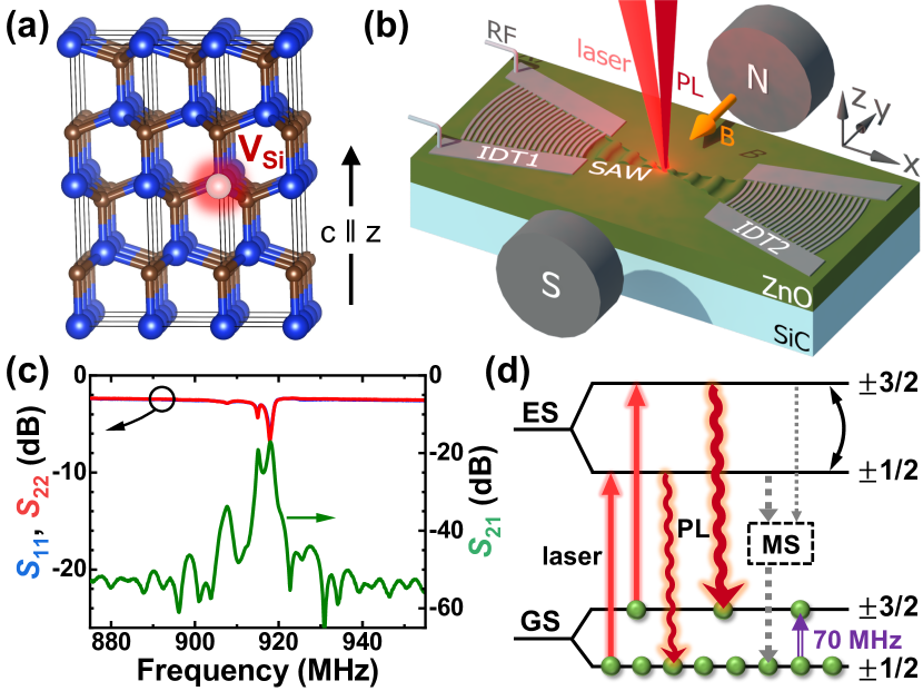
Figure 1(d) displays a simplified energy diagram of the V2 center Soltamov et al. (2015); Ivády et al. (2017) together with the optical pumping and readout scheme Simin et al. (2016). The center has spin 3/2, which is split in zero magnetic field into two Kramer’s doublets due to a low symmetry of the center ( point group). The zero-field splitting between the and doublets is equal to MHz, with the spin quantized along the -axis. Optical excitation into the excited state (ES), followed by spin-dependent recombination via the metastable state (MS), leads to a preferential population of the spin sublevels in the ground state (GS), as indicated by the green dots in Fig. 1(d). As the photoluminescence (PL) intensity is stronger for the states, the PL is sensitive to the resonant spin transitions between the and sublevels (see SM Note (2)) Tarasenko et al. (2018).
The optically detected SAR experiments are performed in a confocal micro-photoluminescence (-PL) setup, as illustrated in Fig 1(b). The SAWs are generated by applying to one of the IDTs an amplitude-modulated RF signal of appropriate frequency. The sample is excited by a Ti-Sapphire laser (at a wavelength of 780 nm) focused onto a spot size of m. The PL band centered around 900 nm (see SM Note (2)) is collected by an objective, spectrally filtered and detected by a photodiode detector connected to an amplifier locked-in to the RF modulation frequency. The GS spin transition frequencies are tuned to the SAW resonance frequency by applying the in-plane magnetic field .
To describe the spin-acoustic interaction of the center in an external magnetic field, we consider an effective spin-3/2 Hamiltonian
| (1) | |||||
| (2) |
Here, is the spin-3/2 operator, is the Bohr magneton, the in-plane -factor, and MHz the zero-field splitting constant. describes the Zeeman splitting in . For , this Hamiltonian yields the GS eigenstates displayed in Fig. 1(d). As discussed below, describes the coupling of the spin and elastic deformations Poshakinskiy and Astakhov (2019); Udvarhelyi and Gali (2018).
Figure 2(a) shows the Zeeman shift of the GS spin sublevels calculated from . For mT, the Zeeman splitting in the GS is larger than the zero-field splitting. Then, the spin quantization axis is along the direction and the spin sublevels shift linearly with the magnetic field. We note that for in-plane magnetic fields, the states with spin projection on magnetic field direction are preferentially populated under optical pumping (as indicated by the green dots). In contrast to the case illustrated in Fig. 1(c), the PL is now stronger for transitions between the ES and GS involving the states (see the light bulbs next to each energy level).
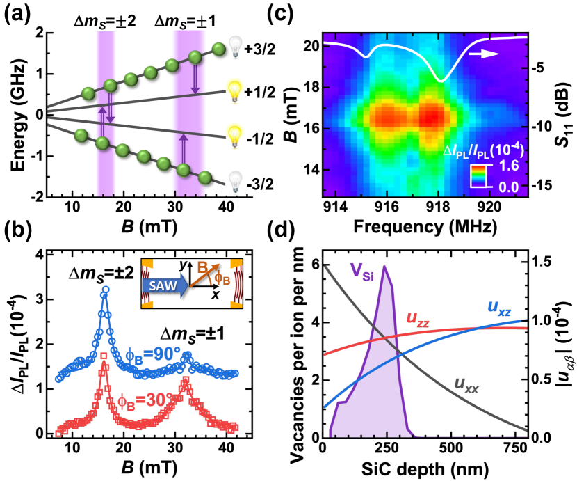
The optically detected SAR as a function of is presented in Fig. 2(b). We observe two resonances at mT and mT, which are ascribed to the acoustically driven and spin transitions, respectively. They agree well with the magnetic field strengths calculated from Eq. (1) for the resonance frequency MHz [cf. double vertical arrows in Fig. 2(a)]. Both resonances are well fitted by a Lorentzian function [solid curves in Fig. 2(b)] with a full width at half maximum (FWHM) of 2.2 mT and 6.0 mT. Note that the resonances are actually doublets, which are split by approximately mT and mT for the and spin transitions, respectively. These splittings are not resolved due to a relatively large broadening caused by a reduction of the spin coherence in proton-irradiated samples with high irradiation fluences Kasper et al. (2020).
A remarkable property of the SAR interaction illustrated in Fig. 2(b) is the ability to selectively couple all spin states within the qudit 333In large magnetic fields considered here, the spin-acoustic interaction does not couple the and states. In case of , any pair within the four spin states can be coupled acoustically.. In particular, the transitions are normally forbidden for RF-driven spin resonance. Therefore, their excitation in Fig. 2(b) represents a clear evidence of the acoustic nature of the observed resonances. To further corroborate this acoustic nature, we display in Fig. 2(c) the intensity of the optically detected SAR as a function of the magnetic field strength (vertical axis) and the RF frequency applied to the SAW resonator (horizontal axis). The SAR signal vanishes as soon as either is changed or is detuned (cf. in the same panel), thus confirming that the spin transitions are caused by the dynamic fields of the SAW. Additional studies summarized in the SM Note (2) show that the spatial dependence of the SAR intensities follow the distribution of the acoustic field within the SAW resonator. We also prove that our experiments are performed in the linear regime for all observed SARs Note (2).
We are now in the position to discuss the anisotropic nature of the spin-acoustic resonances, which is a further important finding of this work. We assume the reference frame illustrated in Fig. 1(b) with the SAW beam propagating along the axis. Figure 2(b) compares the optically detected SAR signal for two angles between the SAW propagation direction and the in-plane magnetic field. While the magnetic field strengths at which the SARs take place are independent of the in-plane orientation of , the SAR intensities do depend clearly on . The full anisotropic behavior with respect to the field orientation on the sample plane is summarized by the circles in Figs. 3(c) and 3(d), which display the intensity of the and SARs, respectively, as a function of .
To understand the unusual angular dependence of the SARs, we develop a microscopic model for the spin-acoustic interaction. In the spherical approximation, the effect of a lattice deformation on a spin center is described by the interaction term
| (3) |
where is the interaction constant Poshakinskiy and Astakhov (2019). Being quadratic in the spin operators, such an interaction can induce spin transitions with as well as with . For , the spin transitions with are induced by the strain tensor components and , while those with are induced by the other linear-independent components , and . The strain components responsible for the spin transitions for other directions can be obtained by the corresponding rotation of the strain tensor.
A plane Rayleigh SAW propagating along is described by the strain tensor
| (4) |
with non-vanishing components , , and Rayleigh (1885). We assume a reference frame for which , , and are purely real. The factor indicates that the phase of the component is shifted by , thus resulting in an elliptically polarized strain field in the plane. Figure 2(d) compares the calculated depth profiles of the , and strain components de Lima, Jr. and Santos (2005) with the simulated depth distribution of the defects Ziegler et al. (2010).
In our case, spin centers are inserted in an acoustic resonator and thus subject to a combination of two counterpropagating SAWs travelling along and with intensities and , respectively. We use the parameter to distinguish different situations: a standing wave (), a traveling wave () or intermediate cases (). The rates and of the spin transitions with and , respectively, are then given by (see SM Note (2))
| (5) |
The transition rates in Eq. (Anisotropic Spin-Acoustic Resonance in Silicon Carbide at Room Temperature) were averaged along to account for the finite detection spot size, which is larger than the SAW wavelength. The angular brackets indicate averaging along to take into account the depth distribution of the centers as well as the strain field, as presented in Fig. 2(d).
Finally, we analyze the symmetry of the SARs. Figs. 3(a)-(b) present the angular dependencies of the and transition intensities, respectively, calculated after Eq. (Anisotropic Spin-Acoustic Resonance in Silicon Carbide at Room Temperature) for various . The SARs are always symmetric with respect to the inversion of the component, since our system has a mirror plane. For , the SARs are also symmetric with respect to the inversion of the component due to additional presence of the time-reversal symmetry. As increases, the latter symmetry breaks as the strain field of the travelling SAW acquires an elliptical polarization. Particularly, Fig. 3(a) shows that the SAR almost vanishes for () while it remains strong for (). Such an asymmetric angular dependence is a clear evidence of the broken time-reversal symmetry in the presence of a travelling SAW. Upon inversion of the SAW propagation direction (, not shown), the angular dependencies of such chiral SAR are flipped with respect to the horizontal axis.
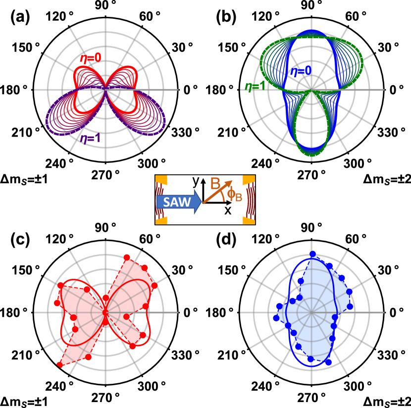
Having developed a microscopic model for the anisotropic SAR, we now apply it to analyze the experimental data given by the circles in Figs. 3(c) and 3(d). The angular dependence of the SAR has a butterfly-like shape with vanishing signal for and maxima when the magnetic field rotates towards or . In contrast, the angular dependence of the SAR has a cocoon-like shape with maxima for . This SAR does not vanish for any direction of the in-plane magnetic field. These measured angular dependences are best reproduced by Eq. (Anisotropic Spin-Acoustic Resonance in Silicon Carbide at Room Temperature) by assuming , which yields the solid lines in Fig. 3(c) and 3(d). This result is consistent with the expected standing-wave nature of the acoustic fields within a resonator. We emphasize that our model has no fitting parameters except for the overall intensity to match the readout optical signal.
In conclusion, we observe half-integer SAR in SiC at room temperature. Using a SAW resonator patterned on the SiC surface, we are able to address both the and the spin transitions of the spin-3/2 center with all-optical readout and without requiring extra microwave electromagnetic fields. The SARs reveal a complex behavior, which depends on the magnetic field orientation with respect to the SAW propagation direction. Our theoretical model describes these angular dependencies without any fitting parameter and predicts chiral spin-acoustic interaction for traveling SAWs. Such a room-temperature hybrid spin-mechanical platform can be used to implement quantum sensors Kraus et al. (2014b) with on-chip SAW control instead of microwave electromagnetic fields Poshakinskiy and Astakhov (2019) as well as to realize acoustically driven topological states Zhang and Niu (2015).
Acknowledgements.
The authors would like to thank S. Meister and S. Rauwerdink for technical support in the preparation of the samples, S. A. Tarasenko and M. Helm for discussions and critical questions, and S. Fölsch for a critical reading of the manuscript. A.V.P. acknowledges the support from the Russian Science Foundation (project 20-42-04405) and the Foundation “BASIS”. G.V.A. acknowledge the support from the German Research Foundation (DFG) under Grant AS 310/5-1. Support from the Ion Beam Center (IBC) at Helmholtz-Zentrum Dresden-Rossendorf (HZDR) is gratefully acknowledged for the proton irradiation.References
- Schuetz et al. (2015) M. J. A. Schuetz, E. M. Kessler, G. Giedke, L. M. K. Vandersypen, M. D. Lukin, and J. I. Cirac, Universal Quantum Transducers Based on Surface Acoustic Waves, Physical Review X 5, 031031 (2015).
- Poshakinskiy and Astakhov (2019) A. V. Poshakinskiy and G. V. Astakhov, Optically detected spin-mechanical resonance in silicon carbide membranes, Physical Review B 100, 094104 (2019).
- Kolkowitz et al. (2012) S. Kolkowitz, A. C. Bleszynski Jayich, Q. P. Unterreithmeier, S. D. Bennett, P. Rabl, J. G. E. Harris, and M. D. Lukin, Coherent Sensing of a Mechanical Resonator with a Single-Spin Qubit, Science 335, 1603 (2012).
- Maity et al. (2020) S. Maity, L. Shao, S. Bogdanović, S. Meesala, Y.-I. Sohn, N. Sinclair, B. Pingault, M. Chalupnik, C. Chia, L. Zheng, K. Lai, and M. Lončar, Coherent acoustic control of a single silicon vacancy spin in diamond, Nature Communications 11, 697 (2020).
- Machielse et al. (2019) B. Machielse, S. Bogdanovic, S. Meesala, S. Gauthier, M. J. Burek, G. Joe, M. Chalupnik, Y. I. Sohn, J. Holzgrafe, R. E. Evans, C. Chia, H. Atikian, M. K. Bhaskar, D. D. Sukachev, L. Shao, S. Maity, M. D. Lukin, and M. Loncar, Quantum Interference of Electromechanically Stabilized Emitters in Nanophotonic Devices, Physical Review X 9, 031022 (2019).
- Lee et al. (2017) D. Lee, K. W. Lee, J. V. Cady, P. Ovartchaiyapong, and A. C. B. Jayich, Topical review: spins and mechanics in diamond, Journal of Optics 19, 033001 (2017).
- Satzinger et al. (2018) K. J. Satzinger, Y. P. Zhong, H. S. Chang, G. A. Peairs, A. Bienfait, M.-H. Chou, A. Y. Cleland, C. R. Conner, É. Dumur, J. Grebel, I. Gutierrez, B. H. November, R. G. Povey, S. J. Whiteley, D. D. Awschalom, D. I. Schuster, and A. N. Cleland, Quantum control of surface acoustic-wave phonons, Nature 563, 661 (2018).
- Takada et al. (2019) S. Takada, H. Edlbauer, H. V. Lepage, J. Wang, P.-A. Mortemousque, G. Georgiou, C. H. W. Barnes, C. J. B. Ford, M. Yuan, P. V. Santos, X. Waintal, A. Ludwig, A. D. Wieck, M. Urdampilleta, T. Meunier, and C. Bäuerle, Sound-driven single-electron transfer in a circuit of coupled quantum rails, Nature Communications 10, 4557 (2019).
- Zhu et al. (2018) H. Zhu, J. Yi, M.-Y. Li, J. Xiao, L. Zhang, C.-W. Yang, R. A. Kaindl, L.-J. Li, Y. Wang, and X. Zhang, Observation of chiral phonons, Science 359, 579 (2018).
- MacQuarrie et al. (2013) E. R. MacQuarrie, T. A. Gosavi, N. R. Jungwirth, S. A. Bhave, and G. D. Fuchs, Mechanical Spin Control of Nitrogen-Vacancy Centers in Diamond, Physical Review Letters 111, 227602 (2013).
- Arcizet et al. (2011) O. Arcizet, V. Jacques, A. Siria, P. Poncharal, P. Vincent, and S. Seidelin, A single nitrogen-vacancy defect coupled to a nanomechanical oscillator, Nature Physics 7, 879 (2011).
- Teissier et al. (2014) J. Teissier, A. Barfuss, P. Appel, E. Neu, and P. Maletinsky, Strain Coupling of a Nitrogen-Vacancy Center Spin to a Diamond Mechanical Oscillator, Physical Review Letters 113, 020503 (2014).
- Golter et al. (2016) D. A. Golter, T. Oo, M. Amezcua, K. A. Stewart, and H. Wang, Optomechanical Quantum Control of a Nitrogen-Vacancy Center in Diamond, Physical Review Letters 116, 143602 (2016).
- Chen et al. (2019) H. Chen, N. F. Opondo, B. Jiang, E. R. MacQuarrie, R. S. Daveau, S. A. Bhave, and G. D. Fuchs, Engineering Electron–Phonon Coupling of Quantum Defects to a Semiconfocal Acoustic Resonator, Nano Letters 19, 7021 (2019).
- Riedel et al. (2012) D. Riedel, F. Fuchs, H. Kraus, S. Väth, A. Sperlich, V. Dyakonov, A. Soltamova, P. Baranov, V. Ilyin, and G. V. Astakhov, Resonant Addressing and Manipulation of Silicon Vacancy Qubits in Silicon Carbide, Physical Review Letters 109, 226402 (2012).
- Falk et al. (2013) A. L. Falk, B. B. Buckley, G. Calusine, W. F. Koehl, V. V. Dobrovitski, A. Politi, C. A. Zorman, P. X. L. Feng, and D. D. Awschalom, Polytype control of spin qubits in silicon carbide, Nature Communications 4, 1819 (2013).
- Li et al. (2007) M. Li, H. X. Tang, and M. L. Roukes, Ultra-sensitive NEMS-based cantilevers for sensing, scanned probe and very high-frequency applications, Nature Nanotechnology 2, 114 (2007).
- Falk et al. (2014) A. L. Falk, P. V. Klimov, B. B. Buckley, V. Ivády, I. A. Abrikosov, G. Calusine, W. F. Koehl, A. Gali, and D. D. Awschalom, Electrically and Mechanically Tunable Electron Spins in Silicon Carbide Color Centers, Physical Review Letters 112, 187601 (2014).
- Whiteley et al. (2019) S. J. Whiteley, G. Wolfowicz, C. P. Anderson, A. Bourassa, H. Ma, M. Ye, G. Koolstra, K. J. Satzinger, M. V. Holt, F. J. Heremans, A. N. Cleland, D. I. Schuster, G. Galli, and D. D. Awschalom, Spin–phonon interactions in silicon carbide addressed by Gaussian acoustics, Nature Physics 15, 490 (2019).
- Kraus et al. (2014a) H. Kraus, V. A. Soltamov, D. Riedel, S. Väth, F. Fuchs, A. Sperlich, P. G. Baranov, V. Dyakonov, and G. V. Astakhov, Room-temperature quantum microwave emitters based on spin defects in silicon carbide, Nature Physics 10, 157 (2014a).
- Soltamov et al. (2019) V. A. Soltamov, C. Kasper, A. V. Poshakinskiy, A. N. Anisimov, E. N. Mokhov, A. Sperlich, S. A. Tarasenko, P. G. Baranov, G. V. Astakhov, and V. Dyakonov, Excitation and coherent control of spin qudit modes in silicon carbide at room temperature, Nature Communications 10, 1678 (2019).
- Udvarhelyi and Gali (2018) P. Udvarhelyi and A. Gali, Ab Initio Spin-Strain Coupling Parameters of Divacancy Qubits in Silicon Carbide, Physical Review Applied 10, 054010 (2018).
- Ivády et al. (2017) V. Ivády, J. Davidsson, N. T. Son, T. Ohshima, I. A. Abrikosov, and A. Gali, Identification of Si-vacancy related room-temperature qubits in 4H silicon carbide, Physical Review B 96, 161114 (2017).
- Kraus et al. (2017) H. Kraus, D. Simin, C. Kasper, Y. Suda, S. Kawabata, W. Kada, T. Honda, Y. Hijikata, T. Ohshima, V. Dyakonov, and G. V. Astakhov, Three-Dimensional Proton Beam Writing of Optically Active Coherent Vacancy Spins in Silicon Carbide, Nano Letters 17, 2865 (2017).
- Note (1) The depth distribution was determined using SRIM (stopping and range of ions in matter) simulation Ziegler et al. (2010).
- Note (2) See Supplemental Material at URL for photoluminescence characterization, ODMR spectrum at zero magnetic field, spatial dependence of the SAR, dependence of the SAR on SAW power, and determination of the matrix elements for the SAW-induced spin transition.
- Sörman et al. (2000) E. Sörman, N. T. Son, W. M. Chen, O. Kordina, C. Hallin, and E. Janzén, Silicon vacancy related defect in 4h and 6h sic, Phys. Rev. B 61, 2613 (2000).
- von Bardeleben et al. (2000) H. J. von Bardeleben, J. L. Cantin, L. Henry, and M. F. Barthe, Vacancy defects in p-type created by low-energy electron irradiation, Phys. Rev. B 62, 10841 (2000).
- Orlinski et al. (2003) S. B. Orlinski, J. Schmidt, E. N. Mokhov, and P. G. Baranov, Silicon and carbon vacancies in neutron-irradiated sic: A high-field electron paramagnetic resonance study, Phys. Rev. B 67, 125207 (2003).
- Tarasenko et al. (2018) S. A. Tarasenko, A. V. Poshakinskiy, D. Simin, V. A. Soltamov, E. N. Mokhov, P. G. Baranov, V. Dyakonov, and G. V. Astakhov, Spin and optical properties of silicon vacancies in silicon carbide - a review, phys. stat. sol. b 255, 1700258 (2018).
- Soltamov et al. (2015) V. A. Soltamov, B. V. Yavkin, D. O. Tolmachev, R. A. Babunts, A. G. Badalyan, V. Y. Davydov, E. N. Mokhov, I. I. Proskuryakov, S. B. Orlinskii, and P. G. Baranov, Optically Addressable Silicon Vacancy-Related Spin Centers in Rhombic Silicon Carbide with High Breakdown Characteristics and ENDOR Evidence of Their Structure, Physical Review Letters 115, 247602 (2015).
- Simin et al. (2016) D. Simin, V. A. Soltamov, A. V. Poshakinskiy, A. N. Anisimov, R. A. Babunts, D. O. Tolmachev, E. N. Mokhov, M. Trupke, S. A. Tarasenko, A. Sperlich, P. G. Baranov, V. Dyakonov, and G. V. Astakhov, All-Optical dc Nanotesla Magnetometry Using Silicon Vacancy Fine Structure in Isotopically Purified Silicon Carbide, Physical Review X 6, 031014 (2016).
- Kasper et al. (2020) C. Kasper, D. Klenkert, Z. Shang, D. Simin, A. Gottscholl, A. Sperlich, H. Kraus, C. Schneider, S. Zhou, M. Trupke, W. Kada, T. Ohshima, V. Dyakonov, and G. V. Astakhov, Influence of Irradiation on Defect Spin Coherence in Silicon Carbide, Physical Review Applied 13, 044054 (2020).
- Note (3) In large magnetic fields considered here, the spin-acoustic interaction does not couple the and states. In case of , any pair within the four spin states can be coupled acoustically.
- Rayleigh (1885) L. Rayleigh, On waves propagated along the plane surface of an elastic solid, Proc. London Math. Soc. s1-17, 4 (1885).
- de Lima, Jr. and Santos (2005) M. M. de Lima, Jr. and P. V. Santos, Modulation of photonic structures by surface acoustic waves, Rep. Prog. Phys. 68, 1639 (2005).
- Ziegler et al. (2010) J. F. Ziegler, M. D. Ziegler, and J. P. Biersack, SRIM - The stopping and range of ions in matter (2010), Nuclear Instruments and Methods in Physics Research B 268, 1818 (2010).
- Kraus et al. (2014b) H. Kraus, V. A. Soltamov, F. Fuchs, D. Simin, A. Sperlich, P. G. Baranov, G. V. Astakhov, and V. Dyakonov, Magnetic field and temperature sensing with atomic-scale spin defects in silicon carbide, Scientific Reports 4, 5303 (2014b).
- Zhang and Niu (2015) L. Zhang and Q. Niu, Chiral phonons at high-symmetry points in monolayer hexagonal lattices, Phys. Rev. Lett. 115, 115502 (2015).