All-electrical detection of skyrmion lattice state and chiral surface twists
Abstract
We study the high-temperature phase diagram of the chiral magnetic insulator Cu2OSeO3 by measuring the spin-Hall magnetoresistance (SMR) in a thin Pt electrode. We find distinct changes in the phase and amplitude of the SMR signal at critical lines separating different magnetic phases of bulk Cu2OSeO3. The skyrmion lattice state appears as a strong dip in the SMR phase. A strong enhancement of the SMR amplitude is observed in the conical spiral state, which we explain by an additional symmetry-allowed contribution to the SMR present in non-collinear magnets. We demonstrate that the SMR can be used as an all-electrical probe of chiral surface twists and skyrmions in magnetic insulators.
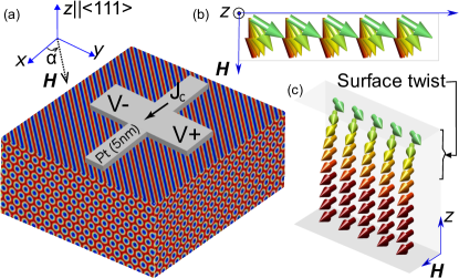
Magnetic skyrmions are nano-scale spin-swirling objects of great interest due to their small size and topological protection Nagaosa and Tokura (2013); Fert et al. (2017). These magnetic solitons are being considered as promising candidates for information bits in ultra compact thin film memory devices where surfaces and interfaces play a crucial role. Recent theoretical studies of chiral magnets showed that their surface magnetization can be strongly modified by the bulk Dzyaloshinskii-Moriya interactions (DMI), leading to a surface structure which deviates from the bulk skyrmion lattice. These so-called chiral surface twists are expected to be prominent in the field-polarized magnetic state restraining the magnetization to fully saturate near the surface along the applied field direction Rybakov et al. (2013). They also affect helicity and stability of three-dimensional skyrmions Rybakov et al. (2013); Meynell et al. (2014); Rybakov et al. (2015); Leonov et al. (2016) and first experimental evidence for the existence of these chiral surface twists has been recently reported for skyrmion tubes aligned perpendicular to the sample surface Zhang et al. (2018). Chiral twists were also observed in thin film multilayers Legrand et al. (2018); Zhang et al. (2020) potentially relevant for skyrmionics applications.
In this paper, we report all-electrical detection of skyrmions in Cu2OSeO3 (CSO). Close to spin-ordering temperature, this chiral magnetic insulator with P symmetry hosts crystals of three-dimensional tubes formed by stacked Bloch-type skyrmions Seki et al. (2012). The effect of the chiral twist on the electrical fingerprint of the skyrmion tubes, which in our device are parallel to the CSO surface, has not been studied so far.
The detection of these surface modifications is difficult, yet important for integration of skyrmions in multi-layered devices. Here, we systematically track the surface magnetization by a detailed investigation of the angular dependence of the spin Hall magnetoresistance (SMR) in the high-temperature part of the CSO phase diagram.
SMR has been used in the past to electrically detect the in-plane magnetization of collinear magnetic insulators Vlietstra et al. (2013); Nakayama et al. (2013); Althammer et al. (2013), non-collinear magnets Aqeel et al. (2015); Ganzhorn et al. (2016); Aqeel et al. (2016, 2017), and antifermagnetic materials Ji et al. (2017); Hoogeboom et al. (2017); Wang et al. (2017); Fischer et al. (2018); Lebrun et al. (2019). In the SMR, the resistance of a heavy metal (Pt) is sensitive to the magnetization direction of an adjacent magnetic layer. In collinear magnets, the SMR is theoretically approximated by the magnetic moment density at the interface Jia et al. (2011); Chen et al. (2013). In addition to a longitudinal resistance change, a transverse voltage arises given by
| (1) |
where and are the in-plane components of the unit vector describing the magnetization direction. For non-collinear magnets with a spin relaxation length, , much smaller than the typical length scale of variation of , the right-hand side of Eq.(1) is replaced by its average over the interface Aqeel et al. (2016):
| (2) |
When the external magnetic field (larger than the saturation magnetic field ) is rotated in the plane of the normal metalmagnet interface, the SMR voltage, , follows a sinusoidal angular dependence with a periodicity of 180∘ (see Fig. 2(a)). This behavior of the SMR is expected when the magnetization is fully aligned with the applied magnetic field. However, any in-plane tilt of the magnetization away from will give rise to an additional phase, , in the angular dependence of making this physical parameter very sensitive to the magnetic structure at the interface.
It is worth noting that previous SMR studies of CSO were performed outside the stability region of the Skyrmion lattice (SkL) phase Aqeel et al. (2016, 2017). The measurements reported here focus on the SkL. We show that the SMR sensitively measures the deviation of the local interface magnetization from , allowing us to probe the highly non-collinear SkL spin texture electrically. The obtained results provide new insights into electrical detection of skyrmions and their surface deformations in magnetic insulators.
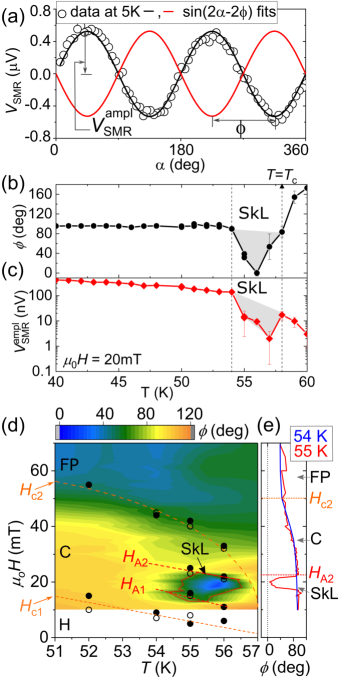
SMR measurements are performed in the device configuration shown in Fig. 1(a), where a 5 nm thick Pt Hall cross is structured onto an oriented polished CSO cuboid (dimensions: 442 mm3). A low frequency ac-current ( Hz) is applied through Pt along the x axis. The SMR is detected in the transverse configuration (along the y axis) by measuring the first harmonic voltage response using a lock-in amplifier Vlietstra et al. (2014) (see Supplementary Material for more details). The angular dependence of the SMR is recorded by rotating the applied magnetic field within the xy-plane parallel to the Pt/CSO interface. Here, the assumption that the SKL follows the field direction, has been recently confirmed in CSO for an in-plane field rotation in a different crystal orientation Zhang et al. (2020). A typical example of the angular dependence of the SMR data measured at 5 K in the ferrimagnetic state of CSO ( mT) is shown in Fig. 2(a). The amplitude and phase are extracted by fitting the data with . Here, is the angle between the applied current and the applied magnetic field, , as defined in Fig. 1(a). The phase is zero, if magnetization is parallel to the field. The dependence with zero phase has been observed in the ferrimagnetic state of CSO at 5K (see Fig. 2(a)). On the other hand, in the helical and low-field conical states, the magnetic moments align almost perpendicular to the propagation vector of the spiral, resulting in Aqeel et al. (2016).
To identify the skyrmion pocket, we recorded the angular dependence of the SMR using two sets of measurement protocols: (i) at fixed fields as a function of temperature (T-scan) and (ii) at fixed temperature, recording the SMR angular dependence at various magnetic fields strengths (H-scan). Figures 2(b) and 2(c) show the T-scan of and extracted from the angular dependence of the SMR signal as exemplified in Fig. 2(a). At mT outside the skyrmion pocket, CSO is expected to be in the conical spiral state, in which is expected. Indeed, we observe that in a wide temperature range except near where a clear dip in the phase is found (labeled as SkL in Fig. 2(b)). A similar signature dip is observed in (see Fig. 2(c); note the logarithmic voltage scale).
To outline the boundaries of the skyrmion pocket, we constructed the high-temperature phase diagram of CSO by mapping the phase as a function of field and temperature using H-scans. Figure 2(d) shows the obtained phase diagram along with the results of ferromagnetic resonance (FMR) measurements which are used here to identify the phase boundaries of the different magnetic states of the CSO crystal. To measure the FMR response, a broad band spin-wave spectroscopy technique Schwarze et al. (2015) is used (see the Supplementary Material for details). The phase boundaries of the FMR data (shown by circles in Fig. 2(d)) agree well with those extracted from the SMR phase . also exhibits distinct anomalies at the magnetic phase transitions, though less pronounced than those in the SMR phase (see Fig. S3 in the Supplementary Material). From the experimentally obtained phase diagram shown in Fig. 2(d), the main observations are as follows: (i) the SkL state is clearly distinguishable from other magnetic states of CSO, and (ii) close to , the phase remains non-zero above . To comprehend these findings, two H-scans of at two temperatures are shown in Fig. 2(e). At 54 K, the phase is almost 90∘ in the helical state and decreases in the conical state of CSO; the lowest values of the phase are observed in the FM state. At 55 K, the phase follows the same trend as observed at 54 K and in addition shows a significant change in the SkL state of CSO. Importantly, in the collinear state (), remains non-zero ( at = 50 mT).
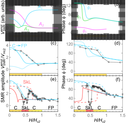
A nonzero SMR phase above provides direct evidence for a chiral surface twist, i.e. the tilt of the magnetization at the interface away from the magnetic field direction Rybakov et al. (2013); Meynell et al. (2014); Rybakov et al. (2015); Leonov et al. (2016). The observed field-dependence of can be understood using Eq. (2) and taking into account the modification of the conical spiral near the surface. We numerically calculated this modification by minimizing the energy of a classical spin model describing CSO with periodic boundary conditions along the in-plane directions and open boundary conditions along the surface normal direction (dotted blue line in Fig. 3(d); see Supplementary Material for details of the calculations). This approach reproduces the experimentally observed decrease of the SMR phase with increasing magnetic field in the conical spiral state and a nonzero value of at the transition to the field-induced collinear state: due to the rotation of spins at the interface away from the magnetic field direction, at and then slowly decreases with increasing magnetic field for , in agreement with our observations (cf. measured data (open circles) with dotted blue line in Fig. 3(d)).
However, this approach fails to explain the observed field-dependence of the SMR amplitude. The calculated reaches its maximal value at and stays constant at higher fields (dotted blue line in Fig. 3(c)). In contrast, the SMR amplitude measured above 50 K is relatively small at . It reaches a maximum at rather low magnetic fields and then decreases with increasing field (see Fig. 3(c)). The origin of this discrepancy can be traced back to Eq. (2) that only involves in-plane magnetization components which become on average larger as the strength of the magnetic field parallel to the interface increases. As a result, the calculated SMR amplitude grows, as tends towards . This discussion shows that the surface twist alone cannot explain the high-temperature SMR data and motivates us to add new phenomenological terms to Eq. (2) allowed by symmetry of the polycrystalline Pt film (rotations around the normal to the film and vertical mirrors):
| (3) |
where is the transverse SMR resistivity. The first term coincides with Eq. (2). The second term is the contribution proportional to the magnetization gradient along the in-plane direction: . This term is sensitive to the presence of the helical spin spiral modulation at the interface, and is proportional to the spiral wavevector, , where is the period of the spiral. The last term proportional to the fourth power of magnetization can originate from higher-order spin torques Hanke et al. (2020) (the higher-order terms in are omitted, for simplicity). The microscopic mechanism behind the second term in Eq. (3) is unclear. According to SMR theory Chen et al. (2013), it should be a correction to the first term, nm being the relaxation length in Pt, whereas our experiment suggests that the contributions of first and second terms of Eq. (3) are comparable.
The field-dependence of these three contributions to the SMR amplitude and phase is shown in Figs. 3(a,b). Both the second and the third terms can explain the observed decrease of with increasing magnetic field. However, the third term gives rise to an extra minimum, which is not observed in experiment. The best fit of the field-dependence of both the amplitude and phase of SMR is obtained for , at 51 K and , at 55 K (solid blue lines in Fig. 3(c-f)). The surprising conclusion is that the contribution of the new term proportional to the magnetization gradient (the second term in Eq. (3)) to the SMR of CSO is comparable to that of the first term in Eq. (3) that works well for collinear magnets.
Although the additional SMR term improves the overall agreement between the calculated and experimental SMR curves, the conical spiral state in the theoretical plots seems to disappear at a field that is lower than deduced from our SMR and FMR measurements (see solid blue lines in Fig. 3(c-f)). This mismatch reflects an interesting effect found by numerical simulations: in addition to the rotation of spins around the surface normal, present in both the collinear and conical states, the conical angle at the interface is smaller than that in bulk. Moreover, it becomes very small at fields well below , so that, in practice, the interface has a lower critical field than the bulk (see Figs. S6 and S7 in the Supplementary Material).
Our simulations also reveal strong sensitivity of the SMR to additional spin interactions at the interface, such as the interfacial Dzyaloshinskii-Moriya interaction (iDMI) enabled by inversion symmetry breaking at PtCSO interface and the strong spin-orbit coupling of Pt. The iDMI with a positive (negative) constant, , decreases (increases) the cone angle of the spiral at the interface, leaving the surface twist angle practically unchanged. Hence, it affects the effective critical field at the interface, which can solve the above mentioned problem. Figures 3(c-f) show that iDMI can improve the agreement between the theoretically calculated SMR amplitude and phase (blue dashed line) and the experimental data. The calculations are done for at 55 K and at 51 K, where is the nearest-neighbor Heisenberg exchange constant.
Finally, we discuss the sudden changes in the experimentally measured amplitude and phase of the SMR associated with the intervening skyrmion lattice phase. Figures 3(e,f) show the field dependence of and in the SkL state calculated numerically using Eq. (3) with and without the iDMI (dashed and solid red lines, respectively). Although minimization of the energy of stable and metastable spin configurations at zero temperature does not allow us to obtain boundaries of the SkL phase near , our calculations show that the SMR in the SkL state can be very different from that in the conical spiral state. In particular, the calculated phase in the SkL state is smaller than that in the conical spiral state at low magnetic fields, which agrees with the observed dip in the SMR phase. In addition, we find a sudden jump in both the phase and the amplitude of the SMR in the SkL state related to an abrupt change of the skyrmion crystal spin configuration at the surface (See Fig. S9 in Supplementary Materials). At high fields, skyrmions are repelled from the edge and spins at the interface are collinear and nearly parallel to the surface. At low fields, the skyrmion centers are residing at the interface, which makes their topological charge smaller than 1 Keesman et al. (2015). The field at which this change occurs is strongly affected by the interfacial DMI (red dashed lines in Fig. 3).
To summarize, our SMR measurements provide a clear evidence for a surface twist in the conical and collinear phases near and make it possible to all-electrically outline the boundaries of the skyrmion crystal phase, at which both the amplitude and the phase of the SMR show a profound discontinuity. The theoretical description of SMR for non-collinear chiral magnets, such as CSO, is more involved than that for collinear ferromagnets. First, SMR is affected by subtle interfacial effects, such as the difference between the surface and bulk critical fields. Second, a new phenomenological term in the SMR expression was required to reproduce the field-dependence of the SMR amplitude. In addition, the SMR was found to be sensitive to interfacial interactions. Our experimental and theoretical results conclusively show that the SMR, as a probe of the surface magnetization, is an important tool for the all-electrical detection of magnetic phase transitions in chiral magnets.
Acknowledgements.
We would like to thank B. J. van Wees, T. Kuschel and J. Bass for useful discussions. This work has been funded by the Deutsche Forschungsgemeinschaft (DFG, German Research Foundation) via project number 107745057 - TRR 80, via SPP2137, as well as via Germany’s Excellence Strategy – EXC-2111 – 390814868, Vrije FOM-programma ‘Skyrmionics’ and the Zernike Institute for Advanced Materials.References
- Nagaosa and Tokura (2013) N. Nagaosa and Y. Tokura, Nature Nanotechnology 8, 899 (2013).
- Fert et al. (2017) A. Fert, N. Reyren, and V. Cros, Nature Reviews Materials 2, 17031 (2017).
- Rybakov et al. (2013) F. N. Rybakov, A. B. Borisov, and A. N. Bogdanov, Phys. Rev. B 87, 094424 (2013).
- Meynell et al. (2014) S. A. Meynell, M. N. Wilson, H. Fritzsche, A. N. Bogdanov, and T. L. Monchesky, Phys. Rev. B 90, 014406 (2014).
- Rybakov et al. (2015) F. N. Rybakov, A. B. Borisov, S. Blügel, and N. S. Kiselev, Phys. Rev. Lett. 115, 117201 (2015).
- Leonov et al. (2016) A. O. Leonov et al., Phys. Rev. Lett. 117, 087202 (2016).
- Zhang et al. (2018) S. L. Zhang, G. van der Laan, W. W. Wang, A. A. Haghighirad, and T. Hesjedal, Phys. Rev. Lett. 120, 227202 (2018).
- Legrand et al. (2018) W. Legrand et al., Science Advances 4 (2018), 10.1126/sciadv.aat0415.
- Zhang et al. (2020) S. Zhang et al., Nano Letters 20, 1428 (2020).
- Seki et al. (2012) S. Seki, X. Z. Yu, S. Ishiwata, and Y. Tokura, Science 336, 198 (2012).
- Vlietstra et al. (2013) N. Vlietstra, J. Shan, V. Castel, B. J. van Wees, and J. Ben Youssef, Phys. Rev. B 87, 184421 (2013).
- Nakayama et al. (2013) H. Nakayama et al., Phys. Rev. Lett. 110, 206601 (2013).
- Althammer et al. (2013) M. Althammer et al., Phys. Rev. B 87, 224401 (2013).
- Aqeel et al. (2015) A. Aqeel et al., Phys. Rev. B 92, 224410 (2015).
- Ganzhorn et al. (2016) K. Ganzhorn et al., Phys. Rev. B 94, 094401 (2016).
- Aqeel et al. (2016) A. Aqeel et al., Phys. Rev. B 94, 134418 (2016).
- Aqeel et al. (2017) A. Aqeel, M. Mostovoy, B. J. van Wees, and T. T. M. Palstra, Journal of Physics D: Applied Physics 50, 174006 (2017).
- Ji et al. (2017) Y. Ji et al., Applied Physics Letters 110, 262401 (2017).
- Hoogeboom et al. (2017) G. R. Hoogeboom, A. Aqeel, T. Kuschel, T. T. M. Palstra, and B. J. van Wees, Applied Physics Letters 111, 052409 (2017).
- Wang et al. (2017) H. Wang et al., Journal of Applied Physics 122, 083907 (2017).
- Fischer et al. (2018) J. Fischer et al., Phys. Rev. B 97, 014417 (2018).
- Lebrun et al. (2019) R. Lebrun et al., Communications Physics 2, 50 (2019).
- Jia et al. (2011) X. Jia, K. Liu, K. Xia, and G. E. W. Bauer, Europhys. Lett. 96, 17005 (2011).
- Chen et al. (2013) Y.-T. Chen et al., Phys. Rev. B 87, 144411 (2013).
- Vlietstra et al. (2014) N. Vlietstra et al., Phys. Rev. B 90, 174436 (2014).
- Schwarze et al. (2015) T. Schwarze et al., Nat. Mat. 14, 478–483 (2015).
- Hanke et al. (2020) J.-P. Hanke et al., Phys. Rev. B 101, 014428 (2020).
- Keesman et al. (2015) R. Keesman et al., Phys. Rev. B 92, 134405 (2015).