advligorts: The Advanced LIGO Real-Time Digital Control and Data Acquisition System
Abstract
The Advanced LIGO detectors are sophisticated opto-mechanical devices. At the core of their operation is feedback control. The Advanced LIGO project developed a custom digital control and data acquisition system to handle the unique needs of this new breed of astronomical detector. The advligorts is the software component of this system. This highly modular and extensible system has enabled the unprecedented performance of the LIGO instruments, and has been a vital component in the direct detection of gravitational waves.
keywords:
real-time processing , feedback control , hardware control , data acquisition| Nr. | Code metadata | |
|---|---|---|
| C1 | Current code version | 4.0~pre |
| C2 | Permanent link to code/repository used for this code version | https://git.ligo.org/cds/advligorts |
| C3 | Code Ocean compute capsule | n/a |
| C4 | Legal Code License | GPLv3 |
| C5 | Code versioning system | git |
| C6 | Software code languages, required tools and services | C/C++, Perl, Python |
| C7 | Compilation requirements, operating environments | C99, Linux OS |
| C8 | Developer documentation/manual | https://dcc.ligo.org/LIGO-E1200653 |
| C9 | Support email | jameson.rollins@ligo.org |
1 Motivation and significance
The development of long baseline gravitational wave detectors over the last 40 years has been of groundbreaking scientific impact. These sophisticated measurement devices are revolutionizing astronomy and astrophysics by providing an entirely new perception of the universe.
The complexity and scale of the LIGO detectors was novel. While prototype interferometer gravitational wave detectors paved the way, their relative simplicity could not provide a clear roadmap for the ultimate design of the LIGO detectors. This was particularly true for the interferometer feedback control systems at the core of the instruments’ operation.
Feedback control enables the LIGO interferometers to maintain the operating point of a highly nonlinear precision optical instrument. Sensors provide information about the state of the interferometers that are fed as error signals to feedback controllers that filter and transform the signals to produce control signals that are fed back to the instrument to actuate on its state. The dynamics of the instruments were extensively modeled before their construction, but the final design of the control loops could not be fully conceived a priori. The feedback controllers needed to be flexible to account for uncertainty in the final feedback control scheme. This motivated a critical decision early in the LIGO design process: to use digital instead of analog feedback control.
At the time, it was unclear if digital control was feasible for this application. There were concerns that digital control loops would have insufficient bandwidth to control the instrument, or that the analogdigital conversion processes would inject too much noise into the feedback loops, limiting the sensitivity of the detectors. Digital communication delays over the four kilometer arm length was also a concern. However, analog electronics are difficult and time consuming to modify, which would have severely limited the rate at which changes to the controllers could have been made and, therefore, the rate of refinement of the instruments. Systems that could have allowed for faster turnaround – by making any potentially desirable parameter changes easily switchable – would have necessarily been complex, difficult to design and maintain, and expensive.
The parameters of digital controllers, on the other hand, can be modified nearly instantaneously, allowing much faster refinement. Further modeling also made clear that excess noise from the digitization and analogization processes could be sufficiently mitigated by proper design of analog signal conditioning, and by expected improvements to the bit depth and noise performance of analogdigital conversion electronics. The increasing speed of computers would allow the bandwidth and complexity of the controllers to steadily increase over time. Ultimately, it was determined that the ease of quick modification - aided by the promising advancements in performance - made digital feedback the necessary choice.
The digital controllers for the Initial LIGO detectors [7] were handwritten C code that was compiled into dedicated real-time Linux kernels. Modular filter banks that allowed for in situ switching of feedback filters and gains were inserted at key points in the feedback path to allow instrument scientists to change the controller response on the fly. The feedback logic itself was hard-coded and difficult to modify. This was sufficient for Initial LIGO, with its small number of feedback control loops. Advanced LIGO was significantly more complicated and required digital feedback controllers that were more flexible.
For Advanced LIGO [3], a more modular, extensible, and usable system was designed from the ground up. The advligorts system gave scientists the ability to visually represent the feedback signal flow and control logic in a more intuitive way using a graphical user interface. The signal flow diagrams could be compiled into real-time code and re-loaded into the front end computers in a matter of minutes, considerably speeding up the turn around time to affect changes on the system.
The advligorts system helped bring the new gravitational wave detectors to fruition, enabling the first detection of gravitational waves in 2015 [4].
2 Software description
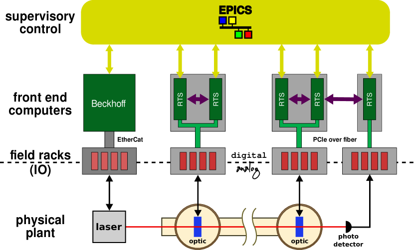
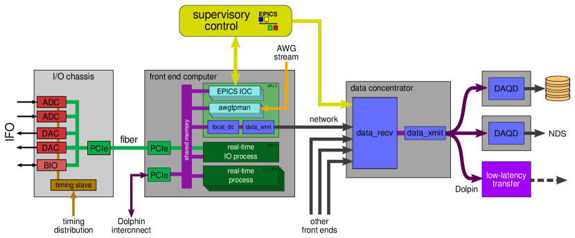
advligorts is the software component of the full Advanced LIGO digital control and data acquisition system (hereafter also referred to as the “real-time system” or “RTS”). The hardware consists of analog-to-digital (ADC) and digital-to-analog (DAC) converters, binary I/O modules, a timing distribution system to clock the ADCs and DACs, and PCIe buses that interface all the hardware to the front end host computers that run the advligorts software (see Figure 1). The advligorts software reads from and writes to the hardware, executes all the digital control logic, and passes data to the data acquisition pipeline. Figure 2 shows a more detailed schematic of this architecture, showing both hardware and software components.
A important feature of advligorts is its use of the Experimental Physics and Industrial Control System (EPICS), a Free and open-source message passing system. EPICS provides a standard interface for operator interfaces (LIGO uses the “MEDM” GUI tool) and supervisory control, such as guardian, the Advanced LIGO automation platform [guardian].
2.1 Software Architecture
The advligorts software consists of three primary components: a patched version of the standard Linux kernel, a real-time code generator (RCG), and a suite of data acquisition daemons (DAQD).
The Linux kernel patch, which is simple and small, allows loadable kernel modules to request that the kernel remove a specific CPU from the normal linux process scheduler and hand it over for exclusive use by the module code. The kernel module can then have uninterruptible use of the CPU at full rate.
Typically advligorts programs are drawn as signal flow diagrams in Matlab Simulink. The RCG takes a Simulink model as input, parses it to extract the signal flow graph, and outputs C code that can execute the same signal flow logic. The RCG adds wrapper code for process synchronization and inter-process communication, then compiles the resulting code into an RTS linux kernel module that can be immediately inserted into the running kernel. The RTS module is completely self sufficient at runtime, requiring no services from the kernel or the rest of the operating system. A special RTS module called an input-output processor (IOP) handles all I/O processing, reading data from the ADCs and passing it to other RTS modules via a shared memory interface, and writing output data passed from RTS modules to the DACs. The IOP processes runs at 65536 Hz, and normal RTS modules can run at any power of two less than that.
Each RTS module employs various user space processes to handle user-facing IO tasks. An EPICS input/output controller (IOC) process exposes writable parameters of the controller logic to an EPICS message passing system [2]. The awgtpman process handles the activation of temporary test point outputs and the processing and insertion of signal injections sent over the network (an interface protocol referred to as “AWG”). Each of these user space processes uses shared memory to exchange data with their respective RTS kernel space processes. Interconnection between RTS processes is achieved either via shared memory for RTS modules in the same kernel, or via a Dolphin PCIe shared memory network [1] for RTS modules on different hosts.
Each front end host computer also runs two processes that collect data from the RTS processes via shared memory (local_dc) and send the data over the network in 1/16th-second chunks (data_xmit). The data acquisition chain receives data from all front ends and collates them into 1/16th-second blocks that are consumed by the DAQD processes which write the data to disk, serve it over the network, or forward it to other streaming processes. In the production environment, the DAQD processes are spread across multiple machines to reduce resource competition.
2.2 Software Functionality
advligorts leverages Matlab Simulink to provide a powerful graphical user interface for users to draw signal flow graphs that can be turned into real-time code (see Section 3). Users can drag and drop parts from an extensive parts library and easily connect them together. The parts library includes parts for all supported I/O interfaces, most math operations, matrices, logic gates, switches, oscillators, demodulation, etc., allowing for essentially arbitrary signal processing.
Most of the parameters of all parts are exposed as process variables through the EPICS interface. Process variables can take the form of floats, integers, or strings, and are used to control switches, set signal gains and matrix coefficients, etc. The EPICS interface also provides monitor test points for the signals passing through the system. Many tools exist to interface with EPICS, including python libraries, command line tools, and various graphical programs for creating operator interface screens.
One of the most important parts is the filter module. Filter modules hold a bank of ten addressable digital filters, each with up to 20 poles and zeros, implemented as cascaded second-order-sections. A companion filter design tool called foton allows users to design filters from scratch, or draw from a library of common filter functions. Once loaded, individual filters can be engaged or disengaged in situ via a single command from the EPICS interface. The filter modules also include excitation inputs, test points, switches for input and output engagement, an additive offset, and a multiplicative gain.
The RCG also allows users to define their own C code functions that can be dropped anywhere in the signal flow graph to perform arbitrary signal manipulations.
The data acquisition daemon provides a Network Data Service (“NDS”) which can be used to access all data acquired by the system in real-time, or to access archival data that has been stored to disk. This service also allows users to request real-time data from virtual test points in the system. The NDS test point interface and the AWG signal injection interface together provide a critical interface for real-time characterization of the system not readily available on other digital signal processing systems. Various supporting applications give scientists the ability to plot the data in both the time and frequency domains, and to make various excition-based measurements of the system.
3 Illustrative Examples
Each Advanced LIGO interferometer employs over 120 RTS models, spread across nearly three dozen front end computers. The data acquisition systems process roughly 10k “fast” channels (with sample rates from 512 - 16k Hz) and nearly 300k “slow” channels (16 Hz, EPICS process variables).
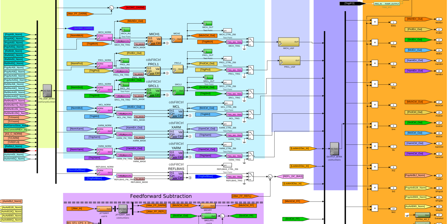
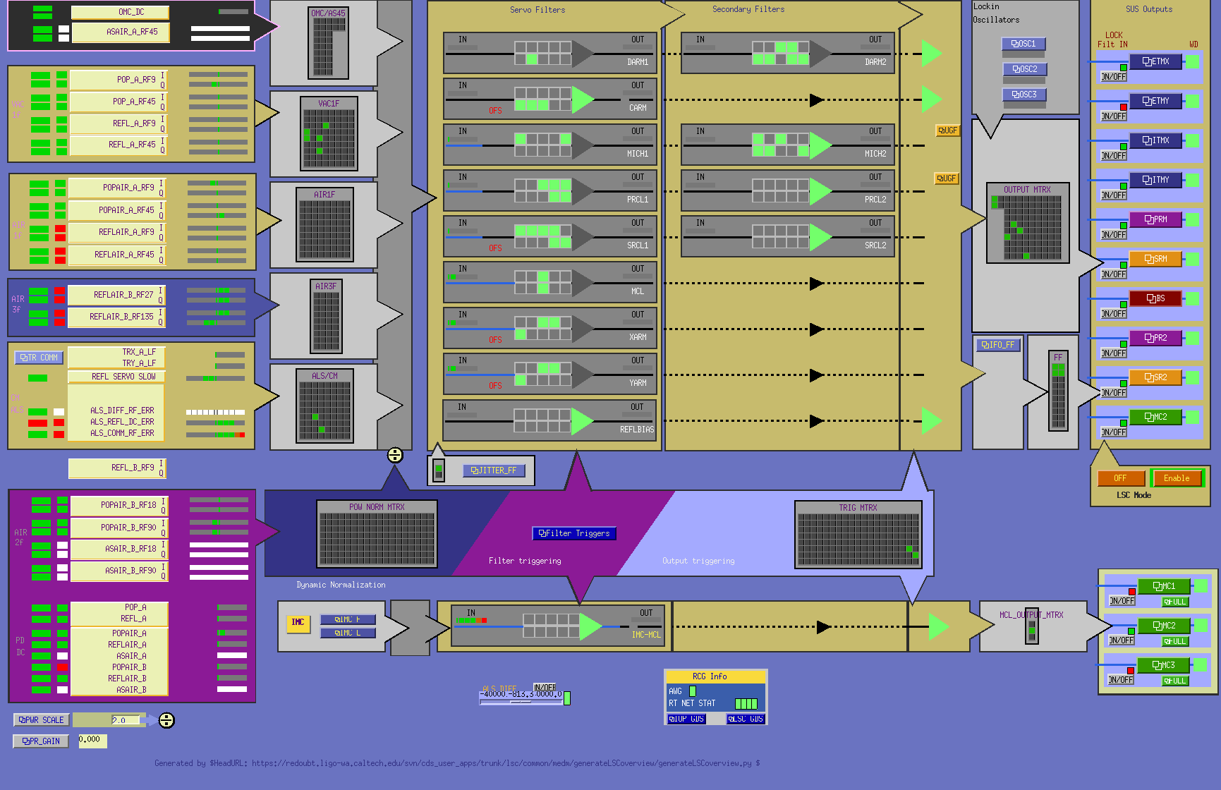
Figure 3(a) shows an excerpt of the Simulink code used to program the real-time controller for the LIGO length sensing and control subsystem which controls the lengths of all the various optical cavities in the Advanced LIGO interferometers. This model runs at 16k Hz, taking as input the RF-demodulated photodetector error signals. It’s outputs are fed over the Dolphin network to separate RTS models that control the suspended optics.
Signal flow is drawn from left to right, with outputs for this block at the far right. The diagram is less busy that it might otherwise be because of the liberal use of GOTO/FROM connections that eliminate the need for drawn lines connecting the output of one block to the input of another. Filter modules are labeled “cdsFiltCtrl”. At the left of the diagram, a gray box represents a matrix (labeled “PD_DOF_MTRX”) that handles “rotation” of sensor input signals into the canonical longitudinal degree of freedom basis for the interferometers. Near the right another matrix (“OUTPUT_MTRX”) handles rotation of signals in the degree of freedom basis into the basis of output suspension drive actuators.
4 Impact
Construction of the Advanced LIGO detectors was completed in 2013. The first gravitational wave was detected in September 2015 [4]. The flexibility, modularity, and ease of programming allowed by the advligorts system was critical for the rapid commissioning of the detectors down to unprecedented sensitivities. The ongoing success of LIGO (there have been dozens more confirmed detections since GW150914 [6]) is a testament to the robustness of this system.
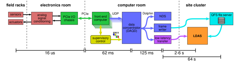
In August 2017, LIGO made the first ever detection of gravitational waves from a binary neutron star merger [5]. With help from the Virgo detector [11], the merger was localized to an area in the sky of roughly 30 deg2 [9]. Within hours of detection and localization, alerts had been sent to the astronomical community and dozens of electromagnetic observatories across the world, who then made the first observation of a gamma-ray burst emitting kilonova [9]. These observations were made possible by a data acquisition system that was able to reliably deliver strain data from the detectors to the search pipelines within a matter of seconds (see Figure 4). The advligorts data acquisition system is the source of this entire pipeline.
Advanced LIGO has already undergone one significant upgrade, installing a squeezed light source which reduces quantum noise at high frequencies [15]. And the more significant “A+” upgrade will commence at the end of the current observing run, adding another new subsystem to shape the quantum noise suppression from the squeezed light source, and further increasing the sensitivity of the current detectors to less than . These upgrades are enabled by the flexibility and extensibility of advligorts framework.
With the success of LIGO, use of the advligorts system is spreading throughout the gravitational wave community. The Japanese project KAGRA [13] has adopted the full Advanced LIGO digital control and data acquisition system for control of their underground gravitational wave detector. advligorts is also used in the GEO 600 project, the Caltech 40m prototype, the MIT LASTI prototype, the AEI 10m prototype, as well as in dozens of smaller laboratories around the world to control a variety of table-top opto-mechanical experiments.
5 Conclusions and future development
LIGO is expected to operate gravitational wave observatories for at least the next two decades. In that time, a third identical detector is expected to be completed in India [10]. Beyond this, a new generation of ground-based detectors is being planned to extend our reach out to the edge of the observable universe [12, 8, 14]. These new detectors will have even more complex controls challenges, and the advligorts system will need to continue to evolved and adapt to meet their needs.
Development is ongoing to improve the usability and extend the functionality of advligorts. A key development track aims to see if the need for a specially-patched linux kernel can be eliminated, by leveraging new features in the standard linux kernel that allow for CPU-isolation for privileged processes. Developers have also been experimenting with running RTS processes in user space. Unprivileged user space execution would not be for real-time operation, but could allow for running code faster than real-time for simulation or testing purposes.
A project is also underway to explore the possibility of executing neural networks within RTS processes. Neural networks trained on simulations and archived data could be ported into RTS processes to enable machine learning experimental control. There is potential for training and updating these networks in real-time, for more sophisticated reinforcement learning applications.
The data acquisition pipeline is being improved to increase the throughput and accessibility of larger amounts of data. Currently, only a small subset of the full channel data is available in low latency, limiting the amount of data characterization that can be done for the low-latency search pipelines. It should be possible to dump the full data pipe into the local LDAS clusters at a fraction of the current time, decreasing latencies for multi-messenger searches and potentially leading to more ground-breaking discoveries.
6 Conflict of Interest
We wish to confirm that there are no known conflicts of interest associated with this publication and there has been no significant financial support for this work that could have influenced its outcome.
Acknowledgments
LIGO was constructed by the California Institute of Technology and Massachusetts Institute of Technology with funding from the National Science Foundation and operates under Grant No. PHY-0757058. Advanced LIGO was built under award PHY-0823459.
References
- [1] Dolphin Interconnect Solutions. https://dolphinics.com/.
- [2] Experimental Physics and Industrial Control System (EPICS). http://www.aps.anl.gov/epics/.
- [3] J. Aasi et al. Advanced LIGO. Classical and Quantum Gravity, 32(7):074001, Mar 2015. doi:10.1088/0264-9381/32/7/074001.
- [4] B. Abbott et al. Observation of gravitational waves from a binary black hole merger. Phys. Rev. Lett., 116(6), Feb 2016. doi:10.1103/physrevlett.116.061102.
- [5] B. Abbott et al. GW170817: Observation of gravitational waves from a binary neutron star inspiral. Physical Review Letters, 119(16), Oct 2017. doi:10.1103/physrevlett.119.161101.
- [6] B. Abbott et al. GWTC-1: A gravitational-wave transient catalog of compact binary mergers observed by LIGO and virgo during the first and second observing runs. Physical Review X, 9(3), Sep 2019. doi:10.1103/physrevx.9.031040.
- [7] B. P. Abbott et al. LIGO: the Laser Interferometer Gravitational-Wave Observatory. Reports on Progress in Physics, 72(7):076901, July 2009, 0711.3041. doi:10.1088/0034-4885/72/7/076901.
- [8] B. P. Abbott et al. Exploring the sensitivity of next generation gravitational wave detectors. Classical and Quantum Gravity, 34(4):044001, Jan 2017. doi:10.1088/1361-6382/aa51f4.
- [9] B. P. Abbott et al. Multi-messenger observations of a binary neutron star merger. The Astrophysical Journal, 848(2):L12, Oct 2017. doi:10.3847/2041-8213/aa91c9.
- [10] B. P. Abbott et al. Prospects for observing and localizing gravitational-wave transients with advanced LIGO, advanced virgo and KAGRA. Living Reviews in Relativity, 21(1), Apr 2018. doi:10.1007/s41114-018-0012-9.
- [11] F. Acernese et al. Advanced virgo: a second-generation interferometric gravitational wave detector. Class. Quantum Grav., 32(2):024001, Dec 2014. doi:10.1088/0264-9381/32/2/024001.
- [12] R. X. Adhikari et al. A cryogenic silicon interferometer for gravitational-wave detection. 2020, 2001.11173. URL http://arxiv.org/abs/2001.11173.
- [13] Y. Aso, Y. Michimura, K. Somiya, M. Ando, O. Miyakawa, T. Sekiguchi, D. Tatsumi, and H. Yamamoto. Interferometer design of the KAGRA gravitational wave detector. Physical Review D, 88(4), Aug 2013. doi:10.1103/physrevd.88.043007.
- [14] M. Punturo et al. The einstein telescope: a third-generation gravitational wave observatory. Classical and Quantum Gravity, 27(19):194002, Sep 2010. doi:10.1088/0264-9381/27/19/194002.
- [15] M. Tse et al. Quantum-enhanced advanced LIGO detectors in the era of gravitational-wave astronomy. Physical Review Letters, 123(23), Dec 2019. doi:10.1103/physrevlett.123.231107.