Liquid Scintillators for Large Area Tracking System
Abstract
We report on studies of non-toxic scintillating liquid useful for large surface detectors. Arrays of liquid scintillators offer a rather simple tool for detecting charged particles traversing a surface and tracking their path through a defined volume. Insertion of wavelength shifting fibres along the liquid scintillating containers significantly improves the light collection at the two ends of the scintillators. We have demonstrated that we can achieve timing resolution of ns) allowing good spatial resolution. Liquid scintillators with fibres read by Photo-multipliers or SiPMs provide an inexpensive alternative technology which suits well the requirement of the MATHUSLA experiment tracking system.
-
January 2020
Keywords: High Energy Physics, Particle Detectors, Liquid Scintillators
1 Introduction
The discovery of the Higgs boson at the Large Hadron Collider (LHC) [1, 2] marked a major success to the ATLAS and the CMS detectors, and opened a new direction of searches for extensions to the Standard Model (SM) of particle Physics. The attention was turned to Beyond the SM (BSM) phenomena not addressed by the SM. Many theoretical frameworks that shed more light on the fundamental mysteries of the SM are expected to include new particles discoverable at the LHC. However, to date all direct BSM searches have produced null results.
A reason for the lack of signs for new physics could be that the searches have been focused on the production of particles, which promptly decay into visible final states very close to the interaction point. A less explored option is that BSM signals first appear as new Long-Lived Particles (LLPs) that decay into SM final states some macroscopic distance away from the production point. LLPs, which arise due to some mechanism suppressing the decay rate of the particle, may be generic extensions to the SM. LLPs are a favorable prediction of a wide range of theories, such as hidden sectors or hidden valleys [3], Neutral Naturalness [4] and Super Symmetry [5, 6], models of Dark Matter e.g. [7] and neutrino extensions such as [8, 9], all of which, can address the fundamental shortcomings of the SM. Neutral LLPs with average decay length above 100 m are particularly difficult to probe, as the sensitivity of the LHC main detectors is limited by challenging backgrounds, triggers, and small acceptances. MATHUSLA is a proposed project for a minimally instrumented, large-volume surface detector above the LHC main detectors ATLAS or CMS. It would search for neutral LLPs produced in High Luminosity LHC collisions by reconstructing displaced vertices in a low-background environment, extending the sensitivity of the main detectors by orders of magnitude in the long-lifetime regime. Neutral LLPs produced at the LHC interaction point travel upwards and decay inside the air-filled111This is required to allow for the detection of LLPs that decay hadronically. decay volume, giving rise to displaced vertices of upwards-traveling charged tracks that are reconstructed by a highly-robust multi-layer tracking system near the roof. The basic principle of the MATHUSLA detector concept is illustrated in figure 1. The Physics case was very well summarised and discussed in details at the white paper [10].
The original simplified design proposed in [11] assumed five layers of Resistive Plate Chambers (RPCs), which are suitable for economical coverage of very large areas ( m2) with good position and timing resolution. In this work we assess the possibility of using liquid scintillator for the active material in the tracker layers. Another promising technology being considered in the MATHUSLA Letter of Intent [12] and the project proposed to the European strategy group [13] is plastic scintillators. Here we look at Liquid scintillator detectors which may serve as another potentially promising alternative to gaseous detectors. This is due to their relative low price and the relative ease in which large volume detector can be constructed.
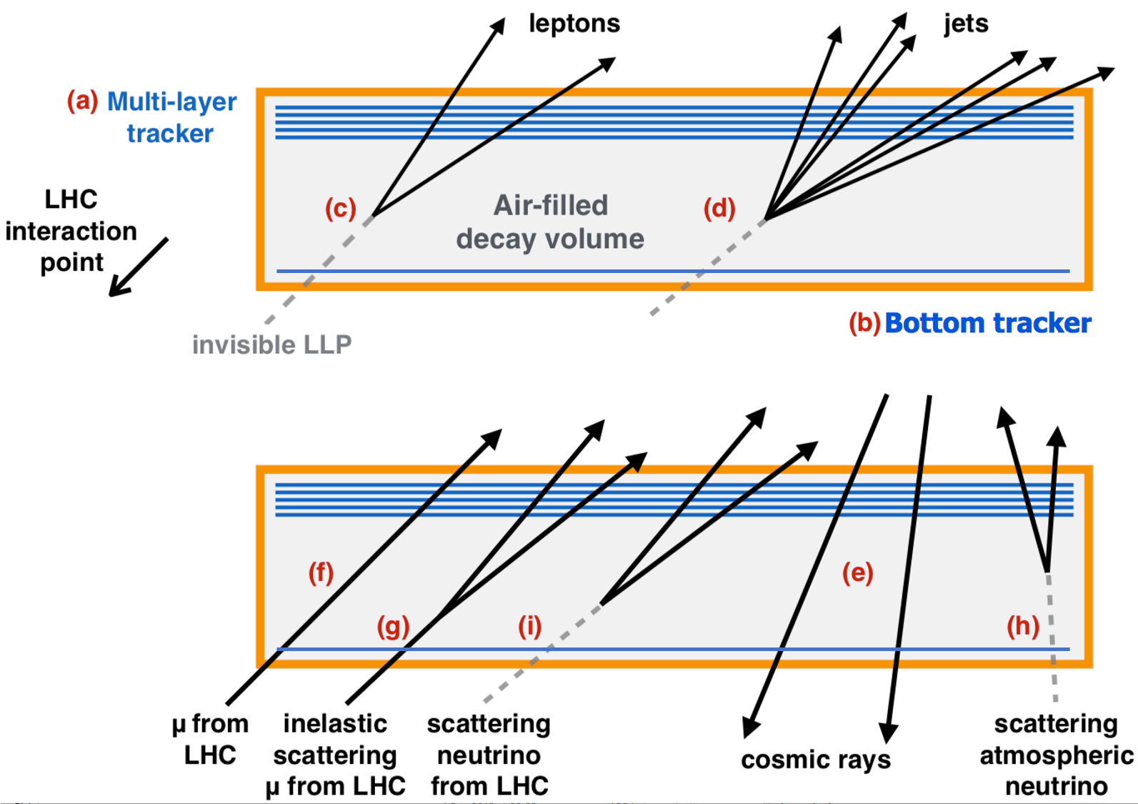
.
2 Methodology
Liquid Scintillators
Liquid scintillators are made of solutions (homogeneous mixture) of scintillating solvent with additional materials dissolved in it, in order to shift the output emission into visible light. Traditionally, liquid scintillators are made with hazardous materials such as toluene, xylene and benzene as the organic solvent (see e.g. [14] or compilation of several options in [15]), this makes the preparation and handling of detectors difficult. We took a different approach of using Linear Alkyl Benzene (LAB), the dominant precursor of biodegradable detergents [16], which is much cheaper, easy to get and less hazardous than commonly used liquid scintillating materials. The clear advantage is that it makes safe handling easy. In addition, LAB has a very good optical transparency ( m) and low amount of radioactive impurities [17]. The typical solutes are fluors such as 2,5-Diphenyloxazole (PPO) with output spectrum peak at 385 nm, and wavelength shifters such as 1,4-bis(5-phenyloxazol-2-yl) benzene (POPOP) or 1,4-bis (2-methylstyryl) benzene (MSB), these are added to the organic scintillators to shift their emission spectrum into the visible range, with emission maximum at 410 nm (POPOP) and 420 nm (MSB). In order to test the feasibility and appropriateness of liquid scintillators for a large area high resolution charged particle detectors, we have conducted several experiments using two different geometries. The geometries used are plane and tube containers both filled with different compositions of liquid scintillating materials.
2.1 Liquid scintillator plane
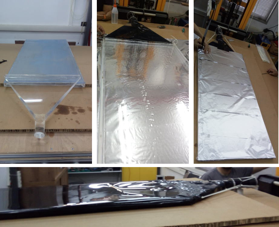
A cm2 plane, 1.2 cm deep of liquid scintillator (figure 2) was constructed using a perspex box covered with aluminium foil. The light emitted from the liquid scintillator is tunnelled by a triangular light guide into a Hamamatsu R329-02 PMT222https://www.hamamatsu.com/eu/en/product/optical-sensors/pmt/index.html which is sensitive to light from 300 nm to 650 nm peaking at 420 nm. The liquid scintillator plate efficiency to cosmic ray muons was measured with a dedicated hodoscope. The hodoscope includes two 3 mm thick round NaI(TI) scintillator counters (diameter 12.5 mm one on top of the other with a gap of 5 mm between the two) readout by multi-anode photomultiplier with a gain of . A picture of the hodoscope is shown in figure 3. Signals from both hodoscope scintillators are discretized and their coincidence serves as a trigger. The efficiency () is then estimated by using equation 1, which is the number of signals collected in the liquid scintillator plane in a 100 ns time window following the hodoscope trigger () divided by the total number of triggered events ().
| (1) |
2.2 Liquid scintillator tubes
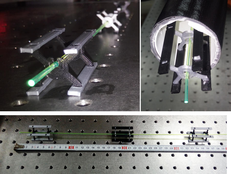
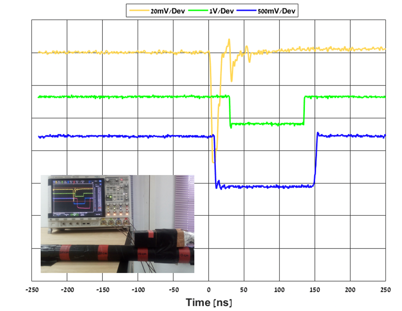
In order to examine the behaviour of the liquid scintillator in tube geometry we have conducted a set of measurements using 1 mm Y11(200) blue to green Kuraray Wave Length Shifter (WLS) fibre with attenuation length m ( given by ref [18] fitting exponential function to the light collected varying the fiber length, , as ). The fiber runs inside the liquid scintillator placed in a box shape 5 cm 10 cm, 1 m long aluminum tube. Dedicated holders, shown in figure 4 keep the fibres centred as well as coupled to the PMT positioned in the end of the tube. Utilizing the same hodoscope as in section 2.1 above the tube (as depicted in the inset of figure 5) we estimated the efficiency of reading signals generated by cosmic ray muons. Figure 5 depicts a scope screenshot of a typical signal read with this setup. Equation 1 is not sufficient for estimating the absolute efficiency of the tube shape scintillators since the angular acceptance of the hodoscope is larger than the tube itself in a non trivial way. As a consequence, relative efficiency was estimated with respect to the efficiency at the nearest position to the PMT (set as ). The relative efficiency graph obtained for different scenarios ( i.e. different concentrations of MSB and distances from the PMT) is shown in figure 6.

3 Results and Discussion
We took data generated by cosmic ray muons while scanning the liquid scintillating plane by shifting the hodoscope to different locations above the surface. The result are the light collection efficiency at various positions with respect to the PMT depicted at figure 7 (top) as well as in a 2D efficiency map shown in figure 7 (bottom). With this setup we managed to obtain a rather homogeneous and high efficiency rate of signal detection with an efficiency drop at the edges of the scintillator. The axes in the two figures indicate the distance from the middle front face of scintillator plane. As seen the efficiency is between and everywhere except for the back corners of the box. The somewhat poor light collection from the back side (furthest from the PMT) of the plane is due to lower level of liquid scintillator material (caused by a slight tilt of the experimental setup). The poor light collection from the rear part manifests as efficiency at the level of to .
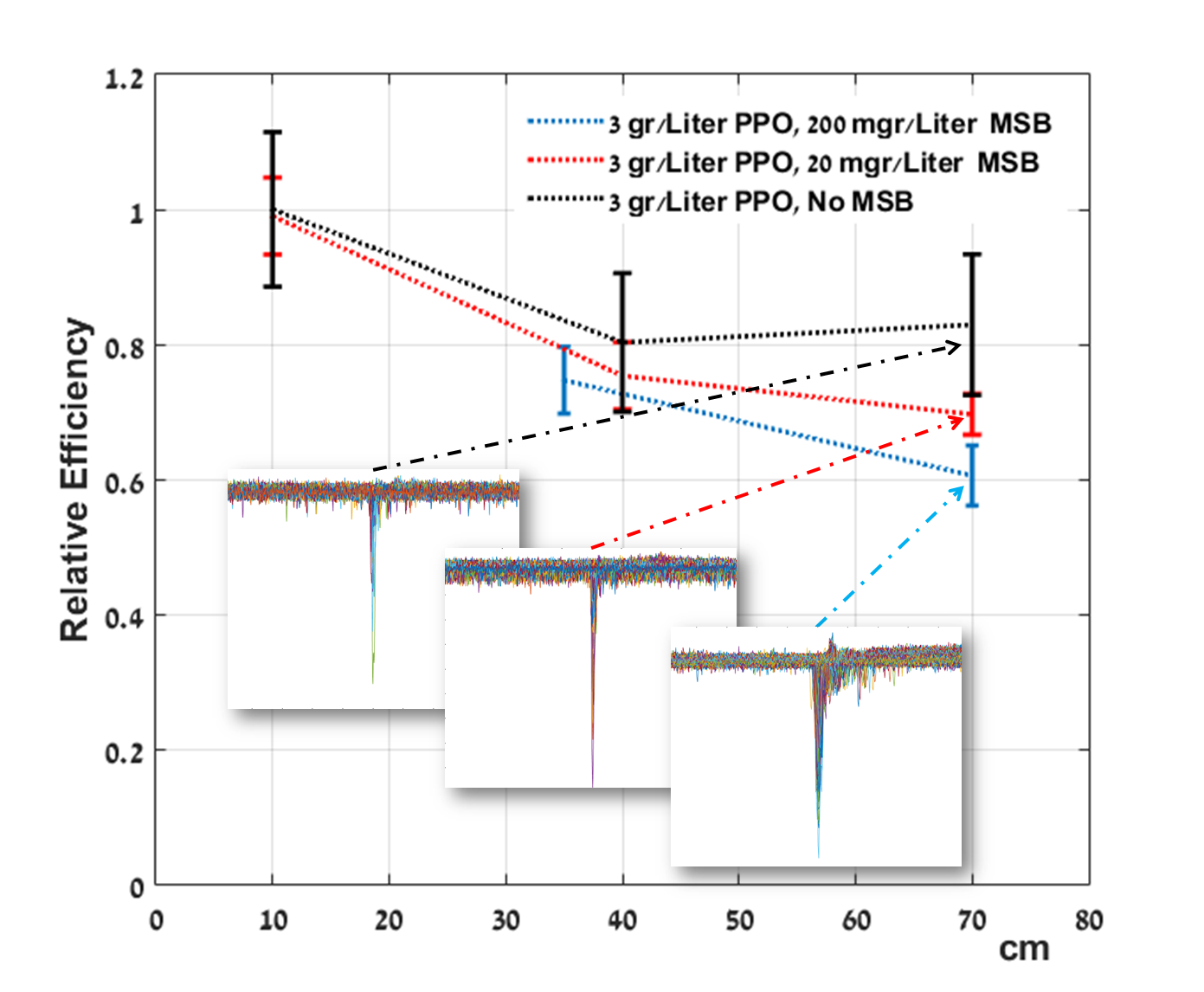
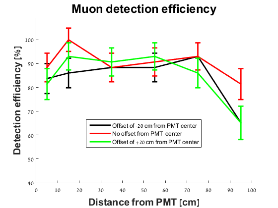
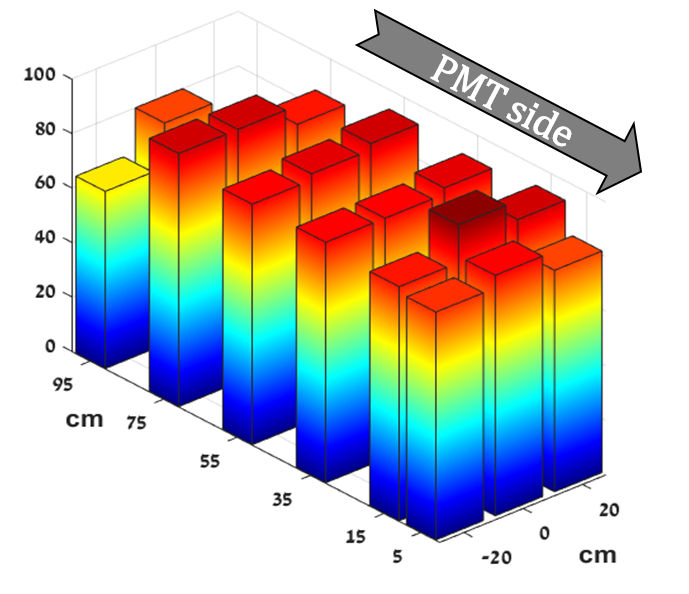
Figure 6 shows the relative muon detection efficiency obtained in the tube geometry with different concentrations of MSB in various distances from the PMT. All measurements are normalized to the maximal efficiency, obtained when the hodoscope was placed 10 cm away from the PMT (set to ). The three insets in the figure show an overlay of all the signals obtained 70 cm away from the PMT. The signals obtained in this setup (from the liquid scintillation tube) are sufficiently fast with full width at half maximum (FWHM) of ns) but the rise time (the time required for the signal to increase from 10% to 90% of the steady state value) is of ns).
While varying the distance between the triggered events to the PMT in our setup and changing the concentration of the MSB in the liquid composition of the tube we observed two effects:
-
1.
The efficiency drops with the distance from the PMT.
-
2.
The efficiency drops as the concentration of the MSB increases (with constant PPO concentration).
Hence, we deduce the following: first, the WLS fibre coupling to the PMT in our setup might not be optimal, second, the addition of MSB is not necessary in order to achieve high detection efficiency. The reason why the addition of MSB degrades the efficiency could be related to the spectral response of the PMT. It is dominated in the violet to ultra violet range, already produced by the PPO ( nm). The additional MSB absorbs photons emitted by the PPO and shifts it to nm with lower efficiency. This process lower the overall efficiency (see ref [19]). In parallel to the studies of liquid scintillators we have examined in the laboratory the usage of extruded scintillating bars read with Silicon Photomultipliers (SiPMs), similar to the MINOS experiment setup [20]. Like in the long tubes of liquid scintillators setup, WLS fibres are used to increase the efficient length range of the bars. Preliminary studies show that one can achieve efficient light collection with fibres as long as three to five meters. The results of these studies will be soon published in a more detailed paper.
4 Summary
The MATHUSLA experiment is a dedicated large-volume displaced vertex detector for the high luminosity LHC runs, designed to be positioned on the surface above one of the main LHC experiments. It is aimed at searching for long-lived particles escaping detection of the underground experiments with up to several orders of magnitude better sensitivity than the current experiments. The distance from interaction point and a desirable angular coverage determines a large detection area of a m2). In our studies we have seen that a large area of tracking system can be realised by layers made with non-toxic liquid scintillators (PPO and MSB dissolved in LAB). A clear advantage of this solution is the simplicity of the construction and detector maintenance and the low cost of the materials. The studies showed that this setup requires further optimization of the exact liquid components. While FWHM of the detected signals is of ns) the fast measured rise time allowing good spatial and temporal resolution. Light collection efficiency for large distances can be improved with the insertion of WLS fibers to liquid scintillators containers. The combination of a few meters long liquid scintillators tubes with WLS fibers, read by SIPMs, provides a inexpensive good alternative building block for the MATHUSLA experiment.
Acknowledgment
The authors would like to thank the PAZY foundation.
References
References
- [1] Aad G et al. (ATLAS) 2012 Phys. Lett. B716 1–29 (Preprint 1207.7214)
- [2] Chatrchyan S et al. (CMS) 2012 Phys. Lett. B716 30–61 (Preprint 1207.7235)
- [3] Strassler M J and Zurek K M 2007 Phys. Lett. B651 374–379 (Preprint hep-ph/0604261)
- [4] Chacko Z, Goh H S and Harnik R 2006 Phys. Rev. Lett. 96 231802 (Preprint hep-ph/0506256)
- [5] Barger V, Giudice G F and Han T 1989 Phys. Rev. D 40(9) 2987–2996
- [6] Dreiner H K 1997 [Adv. Ser. Direct. High Energy Phys.21,565(2010)] (Preprint hep-ph/9707435)
- [7] Cui Y and Sundrum R 2013 Phys. Rev. D87 116013 (Preprint 1212.2973)
- [8] Minkowski P 1977 Phys. Lett. 67B 421–428
- [9] Mohapatra R N and Senjanovic G 1980 Phys. Rev. Lett. 44 912
- [10] Curtin D et al. 2019 Rept. Prog. Phys. 82 116201 (Preprint 1806.07396)
- [11] Chou J P, Curtin D and Lubatti H J 2017 Phys. Lett. B767 29–36 (Preprint 1606.06298)
- [12] Alpigiani C et al. 2018 CERN-LHCC-2018-025, LHCC-I-031 (Preprint 1811.00927)
- [13] Lubatti H et al. (MATHUSLA) 2019 MATHUSLA: A Detector Proposal to Explore the Lifetime Frontier at the HL-LHC (Preprint 1901.04040) URL http://mathusla.web.cern.ch
- [14] Millar C H, Hincks E P and Hanna G C 1958 Canadian Journal of Physics 36 54–72 (Preprint https://doi.org/10.1139/p58-006) URL https://doi.org/10.1139/p58-006
- [15] Barton J C, Barnaby C F, Jasani B M and Thompson C W 1962 Journal of Scientific Instruments 39 360–363
- [16] Kosswig K ”Surfactants, Ullmann’s Encyclopedia of Industrial Chemistry” (American Cancer Society) ISBN 9783527306732
- [17] Chen M 2005 Nuclear Physics B - Proceedings Supplements 145 65 – 68 ISSN 0920-5632 nOW 2004 URL http://www.sciencedirect.com/science/article/pii/S0920563205004755
- [18] Kuraray america, inc., 200 park ave., ny 10166 usa; 3-1-6, nihonbashi, chuo-ku, tokyo 103-8254, japan. URL kuraraypsf.jp/psf
- [19] K.K. Hamamatsu Photonics (2007) Photomultiplier Tubes, Basics and Applications URL www.hamamatsu.com
- [20] Evans J (MINOS) 2013 Adv. High Energy Phys. 2013 182537 (Preprint 1307.0721)