Coordinate Interleaved Orthogonal Design with Media-Based Modulation
Abstract
In this work, we propose a new multiple-input multiple-output (MIMO) concept, which is called coordinate interleaved orthogonal design with media-based modulation (CIOD-MBM). The proposed two novel CIOD-MBM schemes provide improved data rates as well as diversity gain while enabling hardware simplicity using a single radio frequency (RF) chain. Moreover, using the equivalent channel model, a reduced complexity can be obtained for maximum likelihood (ML) detection of the proposed system. Using computer simulations, it is shown that CIOD-MBM schemes provide remarkably better performance against the conventional MBM and CIOD systems.
Index Terms:
Space-time coding, coordinate interleaved orthogonal design, index modulation, media-based modulation.I Introduction
With the proliferation of applications using wireless communication systems in recent years, a huge increase in the number of users and data traffic has emerged. It is envisaged that next-generation wireless communication applications such as Internet-of-Things, vehicle-to-everything communications and molecular communications will be introduced into daily life in the near future [1]. Despite the increasing demand from day to day, the available resources remain limited when considering the frequency spectrum and physical hardware implementations. In next-generation communication systems, under such resource constraints, it is aimed to develop methods with high band efficiency, channel capacity and energy efficiency. All around the world, researchers have eagerly worked to meet these growing demands. As a result of these efforts, many versatile and highly successful methods have been put forward.
Index modulation (IM) schemes, which achieve high data rates while reducing hardware costs in the transmitter, have recently received remarkable attention. Spatial modulation (SM), the well-known member of the IM family, conveys information by transmit antenna indices as well as conventional phase shift keying (PSK) or quadrature amplitude modulation (QAM) methods [2]. When high data rates are desired in SM systems, it is required to make giant increases in the number of transmitting antennas. From this point of view, the media-based modulation (MBM) scheme, which is proposed as an avant-garde digital transmission method for rich scattering environments, is considered as an alternative to SM [3]. In MBM systems, the current distributions of the reconfigurable antennas are changed by means of various elements, such as PIN diodes, varactors, micro-electro-mechanical switches, and so on, hence, different channel fading realizations, which is called as channel states, are obtained. Using the on/off status of the parasitic elements called radio frequency (RF) mirrors, different radiation patterns are acquired by varying current characteristics. If these antenna radiation patterns are sufficiently uncorrelated, distinguishable channel fading realizations can be obtained and used as an additional information source in a rich scattering environment.
Since a single transmit antenna will be active in SM and MBM systems during the transmission, inter-channel interference (ICI) problem is eliminated. On the other hand, the transmission via a single active antenna means that a single RF chain is used in the transmitter part, which greatly reduces the hardware cost. Furthermore, unlike SM, since the spectral efficiency in the MBM varies linearly proportional to the number of RF mirrors, it is sufficient to increase the number of RF mirrors in a bid to achieve high data rates.
Existing multiple-input multiple-output (MIMO) techniques such as SM, quadrature SM (QSM) and generalized SM (GSM) can be integrated with MBM to achieve promising results. In [4], GSM is adopted to MBM in order to enhance spectral efficiency and error performance. Combining QSM and MBM innovatively, promising results are obtained by quadrature channel modulation (QCM) [5]. Space-time coding concept also can be merged with MBM to increase the diversity gain. To this end, space-time channel modulation (STCM) method is proposed in [6], which combines Alamouti’s famous space-time block code (STBC) with MBM. Additionally, considering the flexibility of IM techniques, time-indexed based SM, MBM, and SM-MBM schemes are proposed in [7]. In recent past, since MBM systems are prone to increase physical layer security, various secret transmission scenarios are proposed to enable high secrecy capacity using appropriate designs [8, 9]. Differential MBM (DMBM) [10] concept has alleviated the requirement of channel sounding when it is hard to get accurate channel state information (CSI) at the destination. In [11], a comprehensive frame for space-time coded MBM systems is presented and STBC-based MBM scheme, which uses a single RF chain, is proposed and miscellaneous diversity gains are obtained. In order to overcome fractional bit problems in IM systems, authors propose fractional MBM with golden angle modulation (GAM-MBM) in [12] by making use of the symmetrical structure of GAM.
In this paper, we introduce coordinate interleaved orthogonal design MBM (CIOD-MBM) concept, which provides diversity gain as well as increased spectral efficiency while assuring hardware simplicity using a single RF chain. The focus of this work is to bring the desirable benefits of CIOD, such as enabling low complexity maximum likelihood (ML) detection opportunity and simple transmitter structure, into the area of interest of MBM. In this context, two promising CIOD-MBM schemes, which use a single active antenna during the transmission, are presented. Furthermore, the theoretical average bit error probability (ABEP) of the proposed CIOD-MBM schemes are derived. Afterwards, the supremacy of the proposed CIOD-MBM concept is demonstrated via computer simulations in terms of error performance and obtained numerical results are verified with theoretical results.
II Coordinate Interleave Orthogonal Designs for Media-Based Modulation
In this section, we introduce the system model and the working principle of CIOD-MBM schemes under quasi-static flat Rayleigh fading channel. MIMO transmission scenario is considered by assuming each transmit antenna has RF mirrors. In the proposed systems, CIOD scheme contributes to MBM transmissions as an additional source of information.
The essential principle of CIOD is to achieve diversity gain by transmitting symbols through different channels in two different time slots. Due to the transmission using a single active antenna, reduced hardware cost is obtained keeping only one RF chain. Unlike traditional STBCs, signal constellation must be rotated at a specific angle to ensure the full diversity of CIODs [13]. The CIOD signal matrix for the system with two transmit antennas is as follows
| (1) |
where and are transmitted symbols, which are obtained by partitioning () symbol into its real () and imaginary () part. Here, and are selected from a signal constellation formed by rotating the ordinary -ary signal constellation at a certain angle. For instance, the optimum rotation angle in the quadrature PSK (QPSK) constellation is 13.2885° for the conventional CIOD in (1) [14].
Considering peculiarities of CIOD, two novel CIOD-MBM schemes are designed for a given MIMO system. The generalized baseband received signal model of the CIOD-MBM schemes can be expressed as
| (2) |
where is matrix of the received signals in two different time slots, is the channel matrix, and is the noise sample matrix, respectively. At the same time, represents the CIOD matrix, which is designed for two different MBM schemes. The elements of and follow zero mean independent and identically complex Gaussian distribution with variances and , respectively.
II-A CIOD-MBM I Scheme
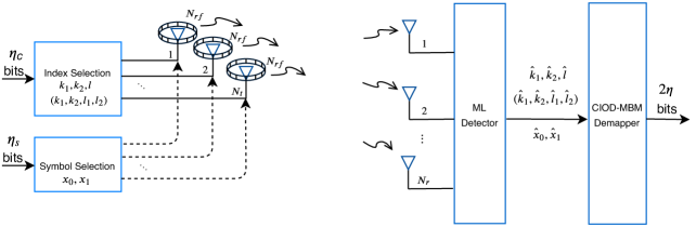
The block diagram of CIOD-MBM I scheme is given in Fig. 1, where and respectively denote the number of index and symbol bits sent in two slots. The spectral efficieny of CIOD-MBM I scheme is calculated as
| (3) |
Before determining the active channel state, available antennas are divided into two groups. Then, using the first bits, active antenna index is determined for the first time slot. The group, to which the first active antenna belongs, is omitted in the second selection. For the determined antenna, active channel state is chosen depending on bits. In the second time slot, second active antenna index is determined as . Then, th channel state is also selected in the second time slot as similar as first time slot. After all, transmitted symbols and are chosen by the aid of last bits. Following these procedures, the transmission matrix is constructed as
| (4) |
where denotes matrix transpose, and possible channel realizations and time slots are represented by rows and columns, respectively.
The CIOD-MBM I scheme provides full diversity when the minimum determinant of the distance matrix is maximized [15]. Under the full rank condition, the minimum coding gain distance is expressed as
| (5) |
In CIOD-MBM I, the rotation angle, which guarantees full diversity, is calculated as ° for QPSK. If the system with , and (QPSK) is considered to exemplify the working mechanism of CIOD-MBM I, spectral efficiency () is calculated as bit/s/Hz. In two time slots, incoming bits are processed as follows:
| (6) |
Using the mapping rule of the CIOD-MBM as shown in Table I, first bits assign the active antenna index set and channel state , respectively. After the two active channel states are separately obtained, the next bits modulate to determine rotated QPSK symbol . Thereafter, last two bits specify the from rotated QPSK symbol set. Finally, CIOD-MBM I matrix is obtained as
| (7) |
| Bits | |||
|---|---|---|---|
| 00 | |||
| 01 | |||
| 10 | |||
| 11 |
II-B CIOD-MBM II
The main motivation of this system is to increase the spectral efficiency of the CIOD-MBM I scheme while maintaining diversity gain and other inherent advantages. The block diagram of CIOD-MBM II can be seen from Fig. 1, which the terms in parentheses represent active antenna and channel state indices of CIOD-MBM II, for and . In the CIOD-MBM II scheme, which is inspired by QSM [16] and QCM [5], active transmit antennas are individually selected for real and imaginary parts of and symbols. The spectral efficiency of the CIOD-MBM II is calculated as
| (8) |
In order to guarantee the utilization of a single RF chain at a single time slot, a total of channel states are divided into two groups similar to the CIOD-MBM I. The first bits decide the active channel state for the initial time slot. After determining the group, to which belongs, active second channel state is determined as . Using bits, active antennas and are selected for real and imaginary parts of transmitted symbols, respectively. Then, the last bits are used to specify the modulated symbols and from rotated -ary constellations. Generalized transmission matrix is given as
| (9) |
where possible channel realizations and time slots are represented by rows and columns, respectively.
| Bits | - | |
|---|---|---|
| 000 | - | |
| 001 | - | |
| 010 | - | |
| 011 | - | |
| 100 | - | |
| 101 | - | |
| 110 | - | |
| 111 | - |
The system with , and is explained by the following example. In this scenario, the spectral efficiency is calculated as bit/s/Hz. ° is the optimum angle that ensures full diversity and maximizes the for QPSK in CIOD-MBM II while ° is the optimum angle for -QAM. For two time slots, it is assumed that incoming bits are arranged as follows:
| (10) |
With the aid of Table II, active antenna set and channel index set are determined by the first index bits. Then, using symbol bits, and are chosen from the rotated constellation as and , respectively. In the final stage, transmission matrix is constructed as
| (11) |
II-C ML Detection for Proposed CIOD-MBM Schemes
As mentioned previous sections, one of the major advantages of CIOD is its symbol-by-symbol decoding possibility while keeping ML complexity remarkably reduced. In this sense, in the proposed CIOD-MBM I scheme, the equivalent system model of (2) is obtained by
| (12) |
where , and represent the equivalent received signal vector, the equivalent transmitted symbols and the equivalent noise vector, respectively. The construction of generalized is shown by
| (13) |
where stands for received signal at th receive antenna in th time slot.
| (14) |
Furthermore, denotes the equivalent channel matrix, which is specified in (14) for CIOD-MBM I. In this notation, () represents channel fading coefficients between the selected active channel state () and th receive antennas, where is chosen from the possible channel realizations depending on and sets. Because of the orthogonality of columns, the equivalent channel matrix is decomposed as where and represent first two and last two columns of . It can be easily observed that and are orthogonal each other, therefore, and are individually decoded for CIOD-MBM I.
As is common, considering the perfect CSI in CIOD-MBM I, ML detection is employed at the receiver by
| (15) |
where represents the Euclidean norm. Similarly, the detection of the index bits is performed by minimization over indices in (15) instead of in CIOD-MBM II scheme.
In CIOD-MBM I, considering all possible channel realizations, minimum ML decision metrics of and are separately obtained by
| (16) |
Thereafter, the minimum ML decision metric for a corresponding antenna and antenna state indices is calculated by . After obtaining all , the most likely antenna and antenna state indices combination is determined by . Using the most likely channel realizations, the transmitted data symbols are estimated by .
After the demapping process, decoded bits are obtained at the receiver. Thanks to the equivalent model, the number of calculated metrics is reduced to for CIOD-MBM I scheme. Due to the non-ortogonality of equivalent channel matrix for CIOD-MBM II, brute-force ML detection is performed as in (15) with a complexity order of .
III Performance Analysis
By the aid of union bounding technique, bit error performance of CIOD-MBM schemes are obtained [17]. Assuming that is transmitted and incorrectly detected as , the ABEP is approximately calculated by
| (17) |
where pairwise bit error probability (PEP) and the number of bit errors are represented by and respectively.
The conditional PEP (CPEP) for the CIOD-MBM schemes can be obtained as
| (18) |
where , is the Frobenius norm and is the well-known -function, which is also represented as . By means of this alternative version of the -function and the moment generating function of [18], the unconditional PEP is given by
| (19) |
where , stand for the eigenvalues of the matrix, which is not equal to zero.
IV Simulation Results
In order to evaluate the error performance of the CIOD-MBM schemes, BER results are produced using computer simulations under varying system parameters. Considering conventional MBM [3], CIOD [13] and CIOD-SM [19] as reference systems, BER results are obtained with respect to , where is the average transmitted energy per bit.
In Fig. 2, theoretical ABEP results of both CIOD-MBM schemes are obtained to compare the BER results obtained by computer simulations.As can be clearly seen, the theoretical curves are perfectly matched with the computer simulation results at moderate and high values. At the same time, the proposed CIOD-MBM schemes offer a flexible design opportunity for varying , and values. As expected, the error performance deteriorates as the number of possible channel realizations increases when the same -ary constellation is used. For increasing values, CIOD-MBM II scheme provides better error performance than CIOD-MBM I scheme as clearly seen in Fig. 2.
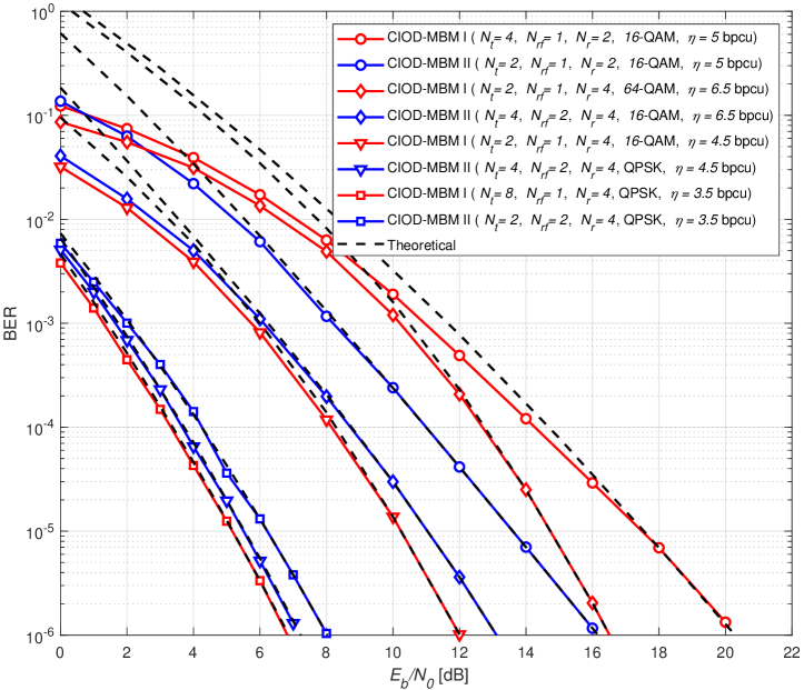
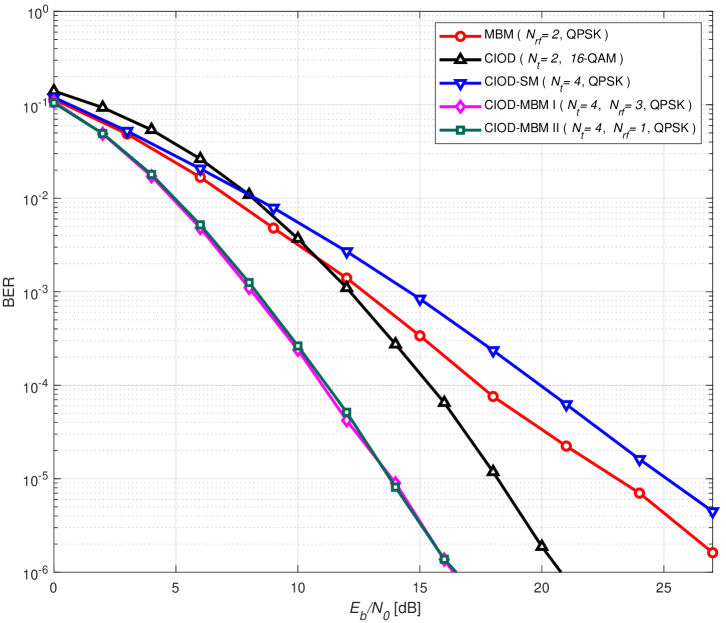
Fig. 3 depicts the BER of the proposed schemes against the BER of conventional CIOD, CIOD-SM and MBM for bit/s/Hz. Here, degree of SM (DoSM) scheme, which is defined in [19], is considered as CIOD-SM. It should be noted that all reference schemes use a single RF chain during the transmission for a fair comparison. As can be clearly seen, CIOD-MBM I scheme provides around 5 dB supremacy over CIOD and approximately 10 dB over CIOD-SM and MBM schemes. At the same time, CIOD-MBM II scheme provides similar error performance with CIOD-MBM scheme for bit/s/Hz while providing better error performance for higher spectral efficiency values as in Fig. 2.
V Conclusions
In this paper, CIOD-MBM concept has been introduced to increase the spectral efficiency of conventional CIOD and MBM schemes by using CIOD as an additional information source as well as transmit antennas, channel states, and amplitude/phase modulation. One of the most weighty benefits of the CIOD-MBM schemes, which promise high data rates by using a low number of transmit antennas, is enabling reduced receiver complexity by symbol-by-symbol detection. As a result of theoretical ABEP and computer simulations, it has been shown that proposed CIOD-MBM schemes provide superiority to reference systems in terms of error performance.
References
- [1] J. G. Andrews, S. Buzzi, W. Choi, S. V. Hanly, A. Lozano, A. C. K. Soong, and J. C. Zhang, “What will 5G be?” IEEE Journal on Selected Areas in Communications, vol. 32, no. 6, pp. 1065–1082, June 2014.
- [2] J. Jeganathan, A. Ghrayeb, and L. Szczecinski, “Spatial modulation: Optimal detection and performance analysis,” IEEE Trans. Wireless Commun., vol. 12, no. 8, pp. 545–547, Aug. 2008.
- [3] E. Seifi, M. Atamanesh, and A. K. Khandani, “Media-based MIMO: Outperforming known limits in wireless,” in 2016 IEEE Int. Conf. on Commun. (ICC), Kuala Lumpur, Malaysia, May 2016, pp. 1–7.
- [4] Y. Naresh and A. Chockalingam, “On media-based modulation using RF mirrors,” IEEE Trans. Veh. Technol., vol. PP, no. 99, pp. 1–16, Oct. 2016.
- [5] I. Yildirim, E. Basar, and I. Altunbas, “Quadrature channel modulation,” IEEE Wireless Commun. Lett., vol. 6, no. 6, pp. 790–793, Aug. 2017.
- [6] E. Basar and I. Altunbas, “Space-time channel modulation,” IEEE Trans. Veh. Technol., vol. 66, no. 8, p. 7609–7614, Aug. 2017.
- [7] B. Shamasundar, S. Bhat, S. Jacob, and A. Chockalingam, “Multidimensional index modulation in wireless communications,” IEEE Access, vol. 6, pp. 589 – 604, Nov. 2017.
- [8] I. Yildirim, E. Basar, and G. K. Kurt, “Media-based modulation for secrecy communications,” Electronics Letters, vol. 54, no. 12, pp. 789–791, June 2018.
- [9] L. Zhang and M. Zhao, “Secrecy enhancement for media-based modulation via probabilistic optimization,” IEEE Commun. Lett., vol. 23, no. 7, p. 1149–1152, July 2019.
- [10] Y. Naresh and A. Chockalingam, “A low-complexity maximum-likelihood detector for differential media-based modulation,” IEEE Commun. Lett., vol. 21, no. 10, p. 2158–2161, Oct. 2017.
- [11] Z. Yigit and E. Basar, “Space-time media-based modulation,” IEEE Trans. Signal Process., vol. 67, no. 9, pp. 2389–2398, May 2019.
- [12] I. Yildirim, E. Basar, and I. Altunbas, “Fractional media-based modulation with golden angle modulation,” in 2019 IEEE Wireless Communications and Networking Conference Workshop (WCNCW), Apr. 2019, pp. 1–5.
- [13] Z. A. Khan and B. S. Rajan, “Space-time block codes from co-ordinate interleaved orthogonal designs,” in IEEE Int. Symp. Information Theory, Lausanne, Switzerland, 2002, p. 275.
- [14] M. Z. A. Khan and B. S. Rajan, “Single-symbol maximum likelihood decodable linear STBCs,” IEEE Trans. Inform. Theory, vol. 52, no. 5, pp. 2062–2091, Apr. 2006.
- [15] H. Jafarkhani, Space-Time Coding. Cambridge, UK: Cambridge University Press, 2005.
- [16] R. Mesleh, S. Ikki, and H. Aggoune, “Quadrature spatial modulation,” IEEE Trans. Veh. Technol., vol. 64, no. 6, pp. 2738–2742, June 2015.
- [17] M. Simon and M. S. Alaouni, Digital Communications over Fading Channels. New York: John Wiley & Sons, 2005.
- [18] G. L. Turin, “The characteristic function of Hermitian quadratic forms in complex normal variables,” Biometrika, vol. 47, no. 1/2, pp. 199–201, June 1960.
- [19] R. Rajasker and K. V. S. Hari, “Modulation diversity for spatial modulation using complex interleaved orthogonal design,” in IEEE TENCON, Cebu, Philippines, Nov. 2012, pp. 1–6.