Skyrmion Pinball and Directed Motion on Obstacle Arrays
Abstract
We examine skyrmions interacting with a square array of obstacles under ac drives applied in one or two directions. For a single direction of ac driving, we find that the Magnus force in conjunction with the obstacle interactions can create elliptical skyrmion orbits of increasing size, leading to localized phases, chaotic phases, and translating or ratcheting orbits. Under two ac drives that are out of phase by and applied in two directions, the skyrmions form localized commensurate orbits that encircle an integer number of obstacles, similar to the electron pinball effect observed for electrons in antidot lattices. As a function of ac amplitude, Magnus force strength, and obstacle size, we find that chaotic scattering regimes and directed motion can emerge even in the absence of asymmetry in the substrate. The directed motion follows different symmetry axes of the periodic substrate, and we observe a variety of reversed ratchet effects. The Magnus force in the skyrmion system produces a significantly larger number of directed motion regimes than are exhibited by overdamped systems. We discuss how these results could be used to move skyrmions in a controlled way for possible applications.
I Introduction
When a classical electron is translating in the presence of a magnetic field, it undergoes cyclic motion with an orbit of radius . If the electron simultaneously interacts with a square periodic array of scatterers, it falls into stable localized orbits for certain values of that allow it to encircle an integer number of scattering sites during each orbit. When is sufficiently small, the electron becomes locked in a localized orbit that fits in the space between the obstacles, but for larger , strong localization occurs when the electron orbit encloses , 2, 4, , or scattering sites, where is an integer Weiss et al. (1991). As the orbit radius varies, the electron remains locked in a localized orbit until it begins to collide with the obstacles and enters a chaotic regime of continuous collisions associated with gradual diffusive motion Weiss et al. (1991); Fleischmann et al. (1992). Samples containing an antidot lattice are commonly known as electron pinball systems in analogy to the pinball game in which a ball is scattered by fixed obstacles. The windows in which commensurate orbits appear depend on the size and periodicity of the scattering sites Ishizaka and Ando (1997); Meckler et al. (2005), and the commensurate orbits can be identified by the peaks they produce in the magnetic transport curves Weiss et al. (1991); Fleischmann et al. (1992); Weiss et al. (1993); Ishizaka and Ando (1997).
Electron pinball effects have been studied for square Weiss et al. (1991); Fleischmann et al. (1992); Weiss et al. (1993), hexagonal Meckler et al. (2005); Kato et al. (2012), rectangular Onderka et al. (2000); Geisler et al. (2005) and disordered dot geometries Klinkhammer et al. (2008); Siboni et al. (2018). More recently, similar effects were studied in graphene superlattice structures Sandner et al. (2015); Power et al. (2017), topological insulators Maier et al. (2017), and bilayer systems, where a pinned Wigner crystal acts as the periodic substrate for commensurate orbits of composite fermions Deng et al. (2016); Jo et al. (2018). Variations on electron pinball include vortex pinball for vortices in a type-II superconductor interacting with a square array of pinning sites under a circulating ac drive, where the size of the vortex orbit depends on the amplitude and frequency of the ac drive Reichhardt and Olson (2002). Similar dynamics arise for colloidal particles interacting with periodic arrays of obstacles or scattering sites under intrinsic or external ac driving or combined ac and dc driving, when the effective ac driving is in both the and -directions and produces circular or elliptical colloidal orbits Tierno et al. (2007); Loehr et al. (2016).
In the absence of a dc drive, particles in a two-dimensional (2D) array under crossed ac drives can also exhibit phase locking and directed motion where a net drift of the particles appears Reichhardt and Olson Reichhardt (2003); Speer et al. (2009); Platonov et al. (2015). This is similar to a ratchet effect in which a net dc transport is produced by an ac drive when the system is coupled to an asymmetric substrate Reimann (2002); however, in the symmetric 2D substrate arrays, the additional symmetry breaking arises from the drive itself or from the interface of two different substrate lattices which can generate edge transport. Recently, a variety of types of directed motion have been studied for magnetic colloids on a periodic substrate where an external magnetic field creates non-trivial loop motion of the colloids, which follow translating skipping orbits along the interfaces between two different substrate lattices Loehr et al. (2016, 2018); Massana-Cid et al. (2019); Yazdi et al. (2020).
Skyrmions in chiral magnets are another example of an assembly of particle-like objects that can interact with various types of ordered and disordered substrates Mühlbauer et al. (2009); Everschor-Sitte et al. (2018); Yu et al. (2010); Nagaosa and Tokura (2013). Magnetic skyrmions have been found in a variety of systems, including materials in which the skyrmions are stable at room temperature Woo et al. (2016); Soumyanarayanan et al. (2017). Skyrmions can be set into motion with an external current Nagaosa and Tokura (2013); Woo et al. (2016); Schulz et al. (2012); Yu et al. (2012); Iwasaki et al. (2013); Lin et al. (2013a), and the resulting velocity-force relations show transitions from pinned to sliding states in transport experiments measuring changes in the topological Hall effect Nagaosa and Tokura (2013); Schulz et al. (2012); Liang et al. (2015) and in direct imaging Woo et al. (2016); Yu et al. (2012); Montoya et al. (2018). It is also possible to characterize skyrmion motion based on changes in the noise fluctuations as a function of drive Díaz et al. (2017); Sato et al. (2019). Interest in skyrmions is spurred in part by possible applications, since due to their size scale and mobility, skyrmions could be used for memory, logic devices, and alternative computing architectures Tomasello et al. (2014); Fert et al. (2017); Prychynenko et al. (2018); Song et al. (2020). The ability to control the direction and distance of skyrmion motion could open new avenues for device creation, and as a result there have been a number of proposals to control skyrmion motion through interactions with structured substrates such as race tracks Tomasello et al. (2014); Fert et al. (2017), periodic substrate modulations Reichhardt et al. (2015a); Reichhardt and Reichhardt (2015, 2016); Navau et al. (2016), or ordered pinning structures Ma et al. (2016, 2017); Stosic et al. (2017); Fernandes et al. (2018); Toscano et al. (2019). For example, one control technique is to have the skyrmions interact with a 2D periodic substrate such as an anti-dot array Reichhardt et al. (2015b); Saha et al. (2019); Feilhauer et al. (2019); Vizarim et al. (2020a).
A dynamical feature that distinguishes skyrmions from many other particle systems is the strong non-dissipative Magnus or gyroscopic component of the skyrmion motion produced by their topology Everschor-Sitte et al. (2018); Nagaosa and Tokura (2013); Vizarim et al. (2020a), which affects both how the skyrmions move under a drive and also how they interact with a substrate potential. On a smooth landscape, a driven skyrmion moves at an angle with respect to the driving direction known as the skyrmion Hall angle Everschor-Sitte et al. (2018); Nagaosa and Tokura (2013); Everschor-Sitte and Sitte (2014); Reichhardt et al. (2015c), which increases as the ratio of the Magnus force to the damping term increases. In experimental measurements, skyrmion Hall angles ranging from just a few degrees up to have been observed Jiang et al. (2017); Litzius et al. (2017); Woo et al. (2018); Juge et al. (2019); Zeissler et al. (2020); however, it is expected that much larger Hall angles could arise in certain skyrmion-supporting materials Nagaosa and Tokura (2013). In devices such as a race track memory, the skyrmion Hall angle strongly limits the distance the skyrmion can move before it reaches the edge of the sample, and as a result, a variety of studies have focused on methods for controlling the skyrmion Hall angle. In the presence of pinning, the skyrmion Hall angle develops a drive or velocity dependence, increasing from a value of nearly zero just above the depinning threshold to a saturation at the pin free value for high drives Reichhardt et al. (2015c); Jiang et al. (2017); Litzius et al. (2017); Woo et al. (2018); Juge et al. (2019); Zeissler et al. (2020); Müller and Rosch (2015); Kim and Yoo (2017); Legrand et al. (2017); Reichhardt and Reichhardt (2019a, b, 2020). This behavior can result from a side jump effect that occurs when the skyrmion interacts with the pinning sites which diminishes in magnitude as the skyrmion velocity increases Saha et al. (2019); Müller and Rosch (2015); Reichhardt and Reichhardt (2020); Litzius et al. (2020). Other effects such as skyrmion distortions can also alter the skyrmion Hall angle Litzius et al. (2017, 2020).
Nanostructuring techniques can be used to create periodic pinning landscapes for skyrmions in which the pinning sites act as repulsive or attractive scattering sites Stosic et al. (2017); Fernandes et al. (2018); Feilhauer et al. (2019). Particle based simulations examining the motion of skyrmions in the presence of 2D arrays of scattering sites show that at low drives, the skyrmions move in the direction of the drive, while at higher drives, the skyrmion Hall angle is quantized and the skyrmion motion locks to different symmetry directions of the underlying substrate Saha et al. (2019); Feilhauer et al. (2019); Vizarim et al. (2020a), similar to the dynamical symmetry locking found in overdamped systems such as dc driven superconducting vortices Reichhardt and Nori (1999) or colloids Korda et al. (2002); MacDonald et al. (2003); Reichhardt and Reichhardt (2012). In the overdamped systems, the direction of the external drive must be changed to observe the dynamical locking, whereas in the skyrmion system, the drive direction is fixed. Skyrmions moving over 2D substrates under combined dc and ac driving exhibit various types of locking effects including Shapiro steps and transverse phase locking Vizarim et al. (2020b).
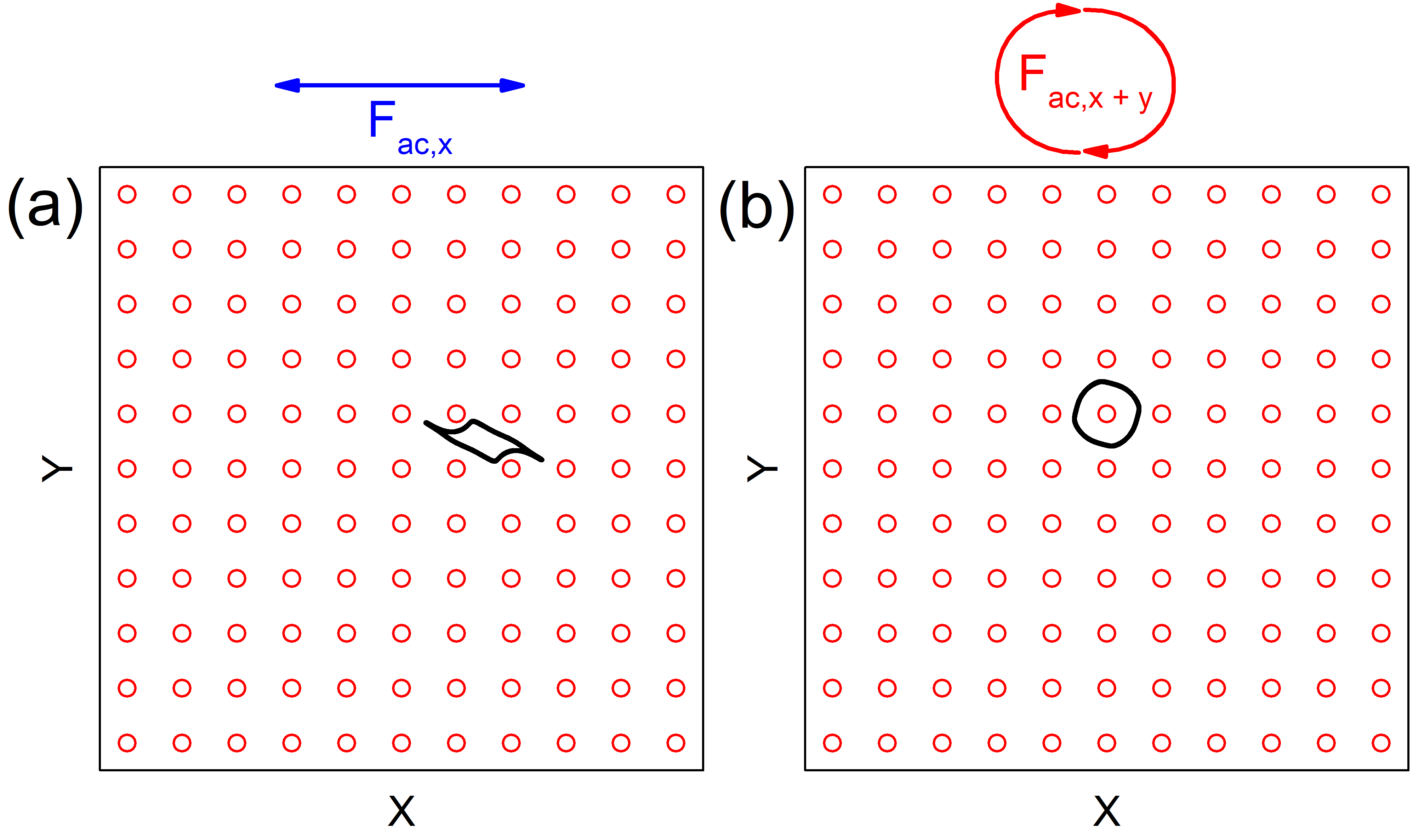
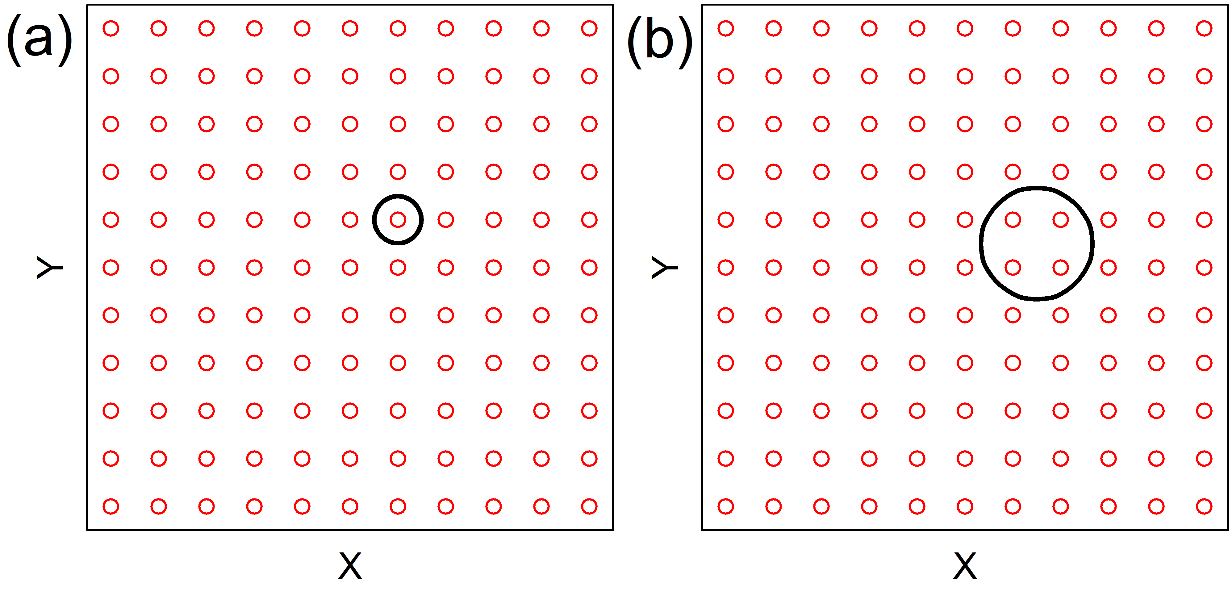
In this work we examine skyrmions interacting with a two dimensional periodic array of obstacles or antidots and subjected to either a linear or a circular ac drive, as shown in Fig. 1. Under linear ac driving, the Magnus force makes it possible to observe two-dimensional skyrmion orbits as well as directed motion in which the skyrmions translate due to a symmetry breaking of the orbits by the Magnus force. Under circular ac driving, an even richer variety of dynamical phases appear, including localized periodic orbits as well as localized or diffusing states similar to but more varied than those found in the electron pinball systems. We also observe a series of ratcheting orbits for certain ac amplitudes and frequencies along with reversals of the ratchet effect. Our results suggest that ac driving provides a new method for controlling skyrmion motion and achieving topological transport.
II Simulation
We consider a two-dimensional system of size with periodic boundary conditions containing obstacles placed in a square array. A single skyrmion is added to the sample and subjected to either a linear ac drive applied along the -direction, as shown in Fig. 1(a), or a circular ac drive composed of two perpendicular ac drives that are out of phase by , as shown in Fig. 1(b). The skyrmion dynamics are obtained from a particle based or modified Theile equation approach as used in previous work Reichhardt et al. (2015b); Vizarim et al. (2020b); Lin et al. (2013b); Brown et al. (2019); Xiong et al. (2019). The equation of motion is given by
| (1) |
The first term on the left of magnitude is the damping term, which aligns the skyrmion velocity with the net external forces experienced by the skyrmion. The second term on the left is the Magnus force, which produces a velocity component perpendicular to the net forces on the skyrmion. The obstacle interaction force arises from obstacles with a Gaussian potential energy , where is the strength of the obstacle potential, is the distance between skyrmion and obstacle , and is the obstacle radius. The force between the obstacles and the skyrmion is given by , where . For computational efficiency, we cut off the interaction beyond , since it becomes negligible at larger distances. We use an obstacle density of , where the dimensionless unit of length is . The ac driving force is given by
| (2) |
For linear driving, , while for circular driving, both and are nonzero. In each simulation we fix the frequency values and and increase the ac amplitudes and in increments of every simulation time steps. For each ac drive amplitude value we measure the skyrmion velocity in the direction and in the direction, where the average is taken over 100 ac drive cycles. Under our normalization, a value or indicates that the skyrmion is translating by one substrate lattice constant per ac drive cycle in the or direction, respectively.
III Skyrmion Pinball
III.1 Linear ac Drive
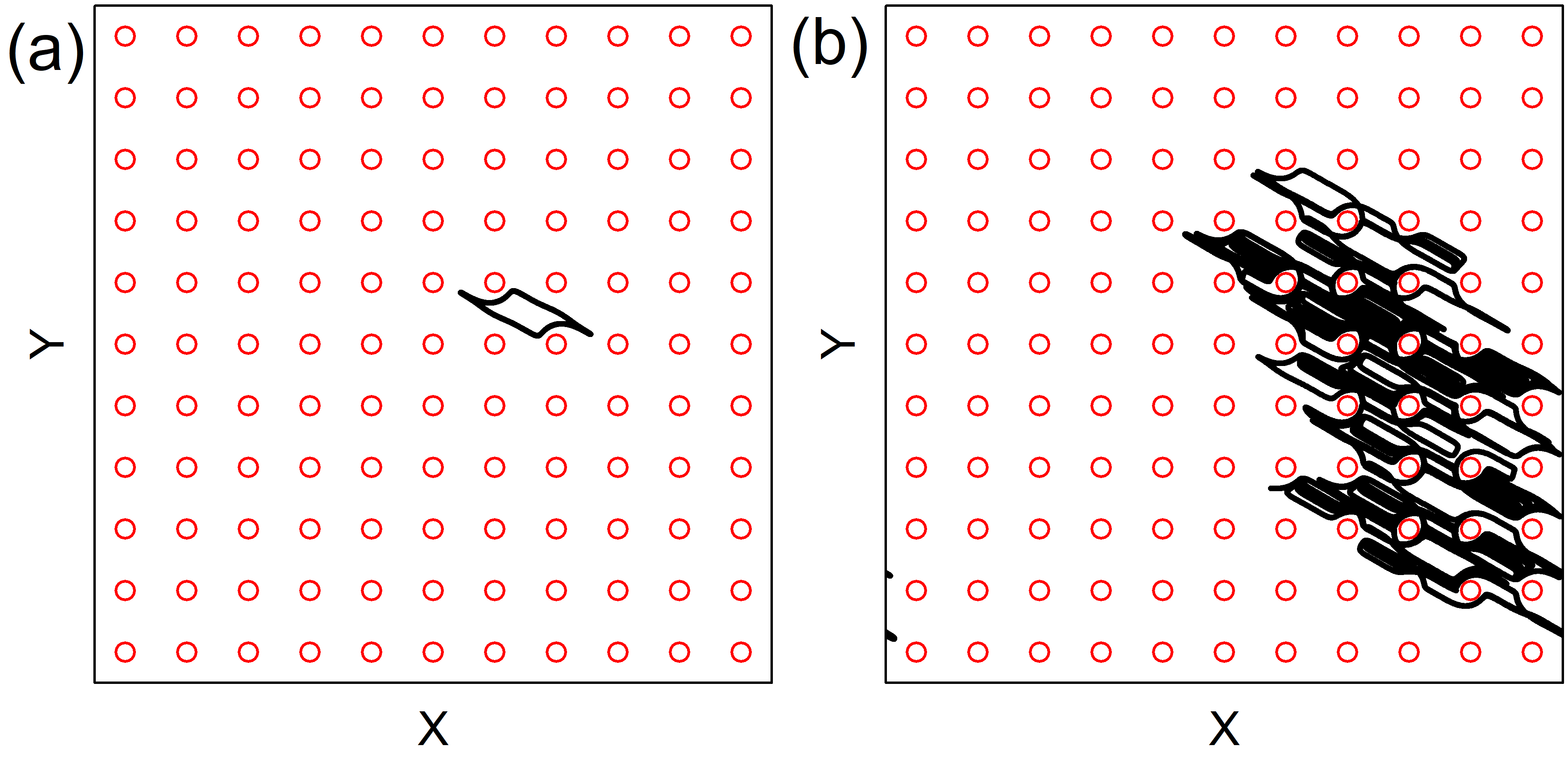
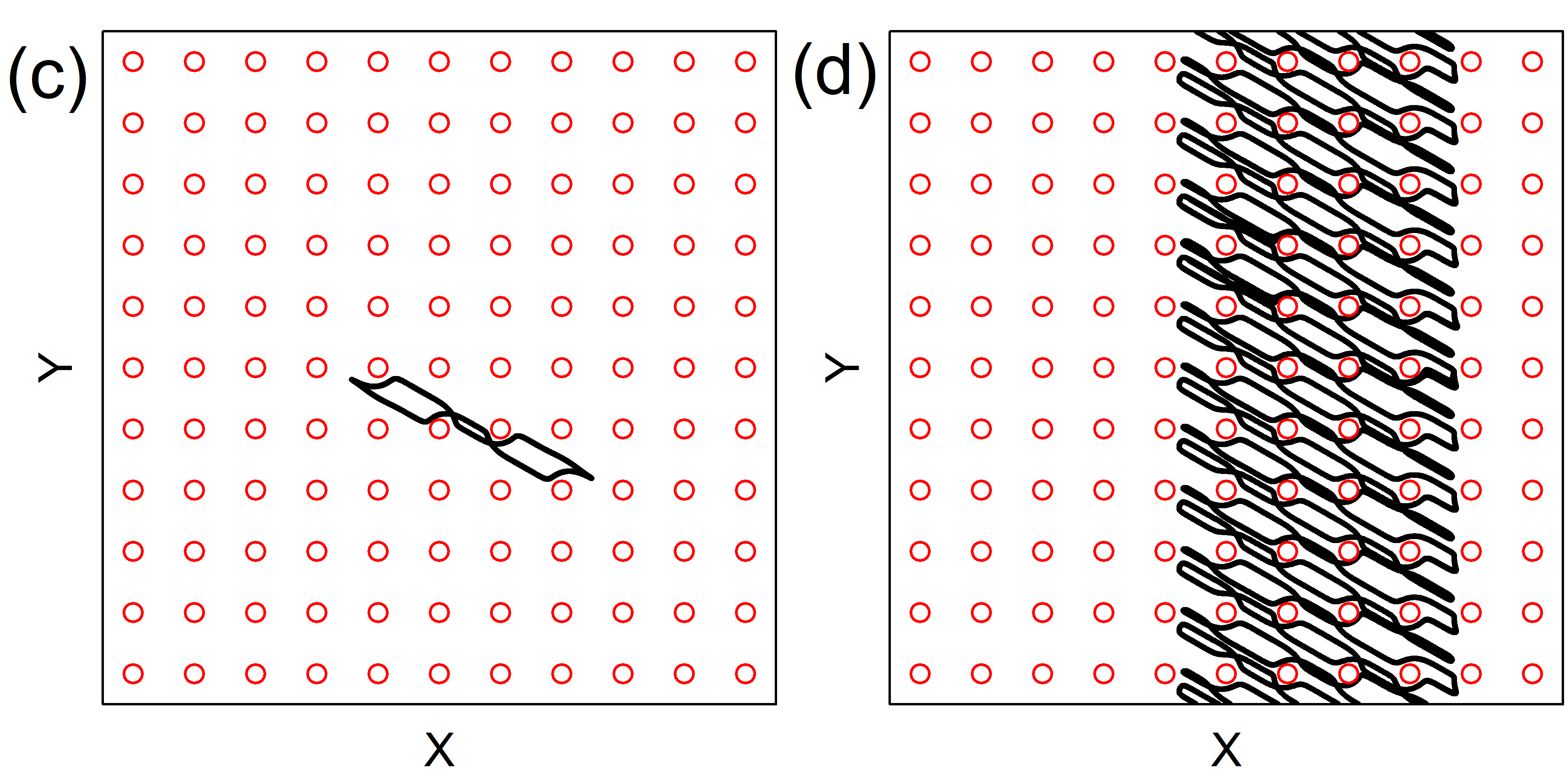
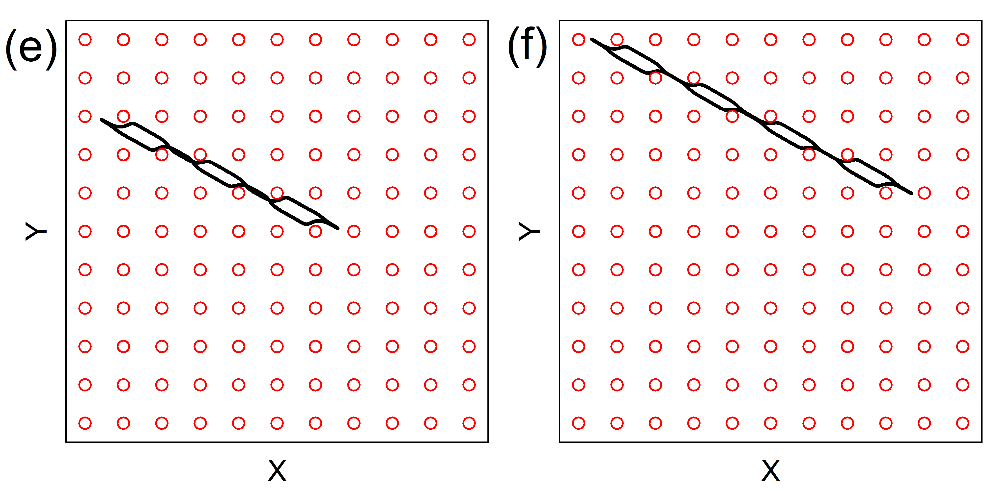
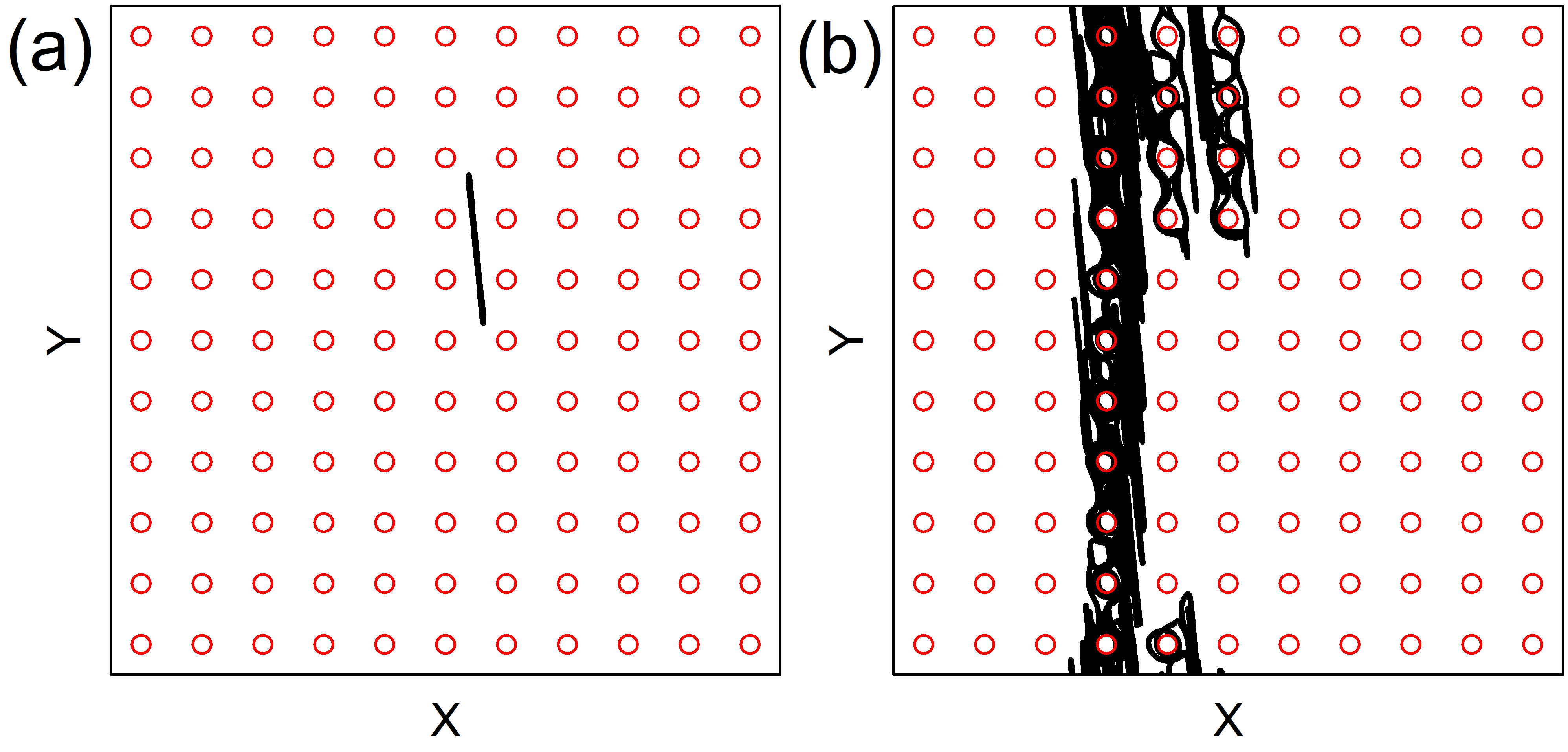
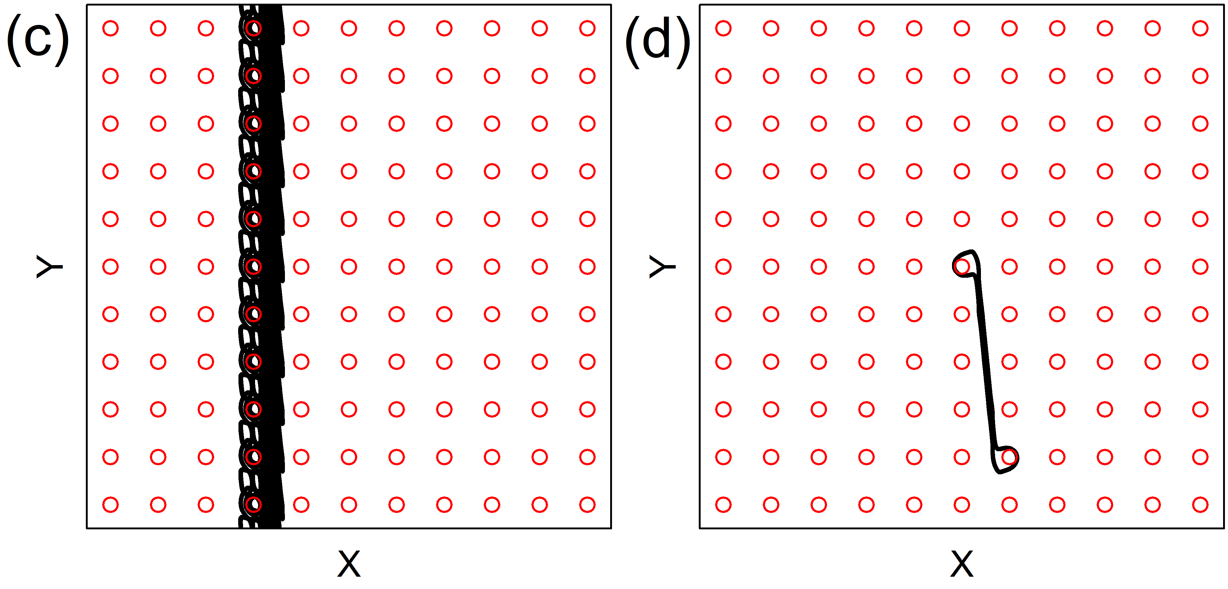
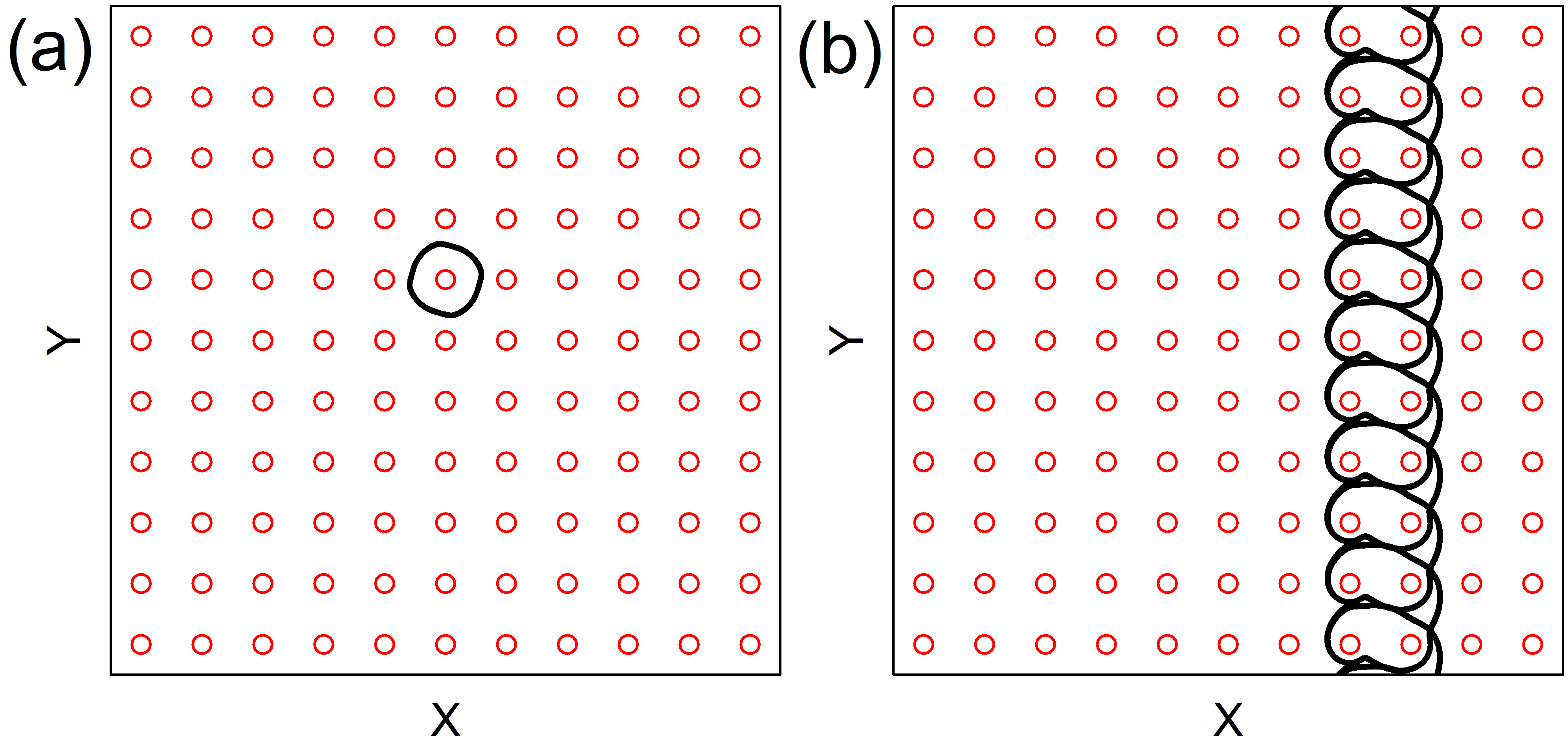
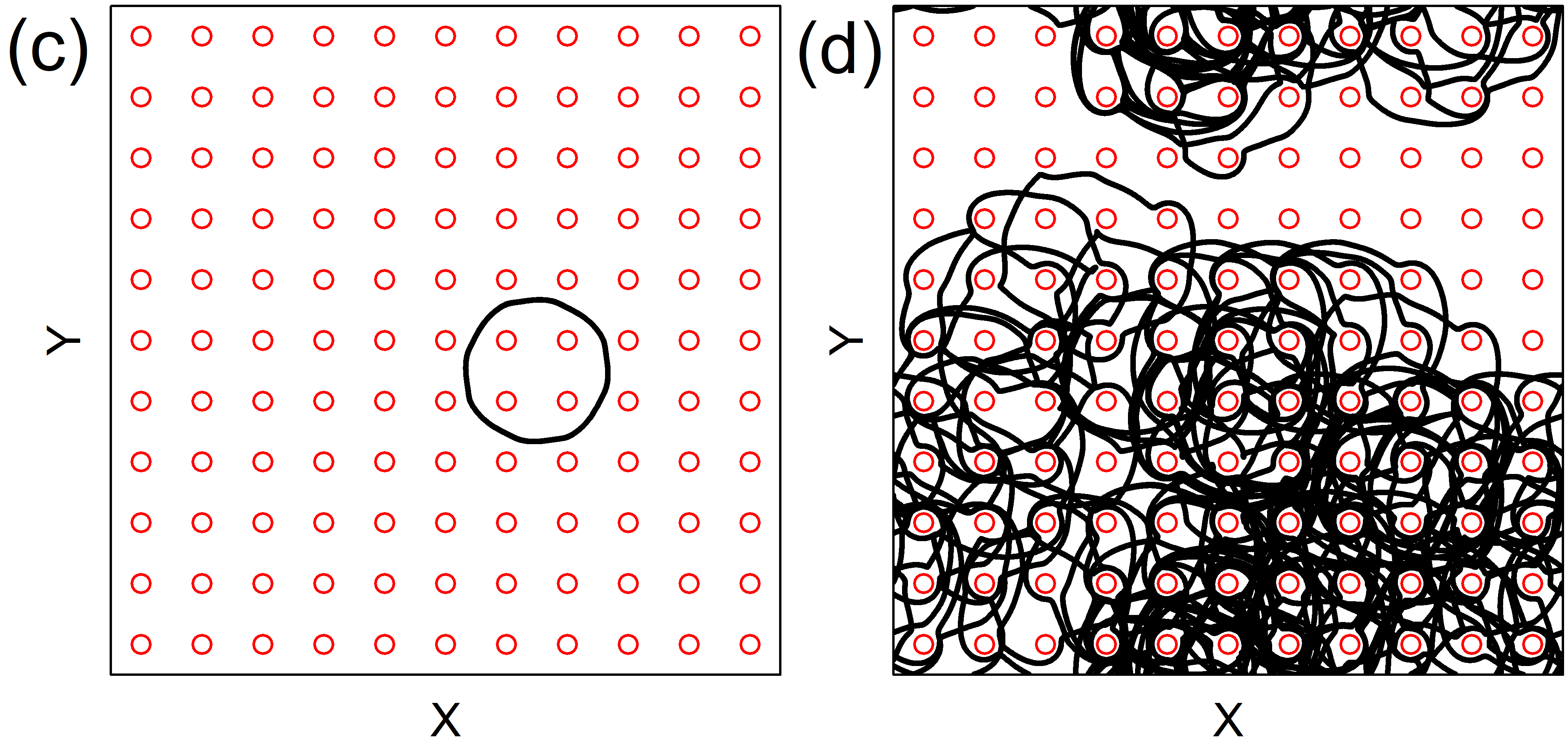
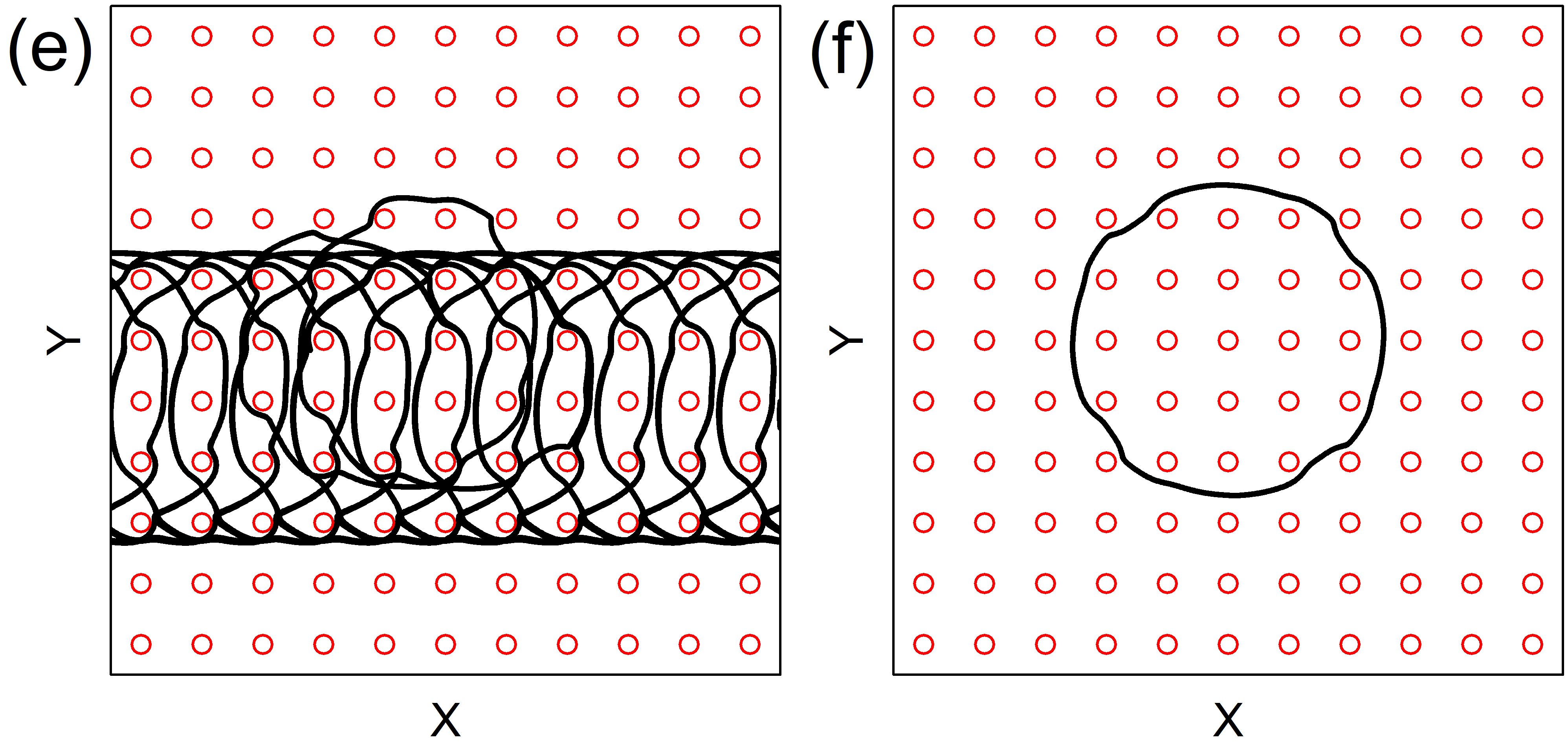
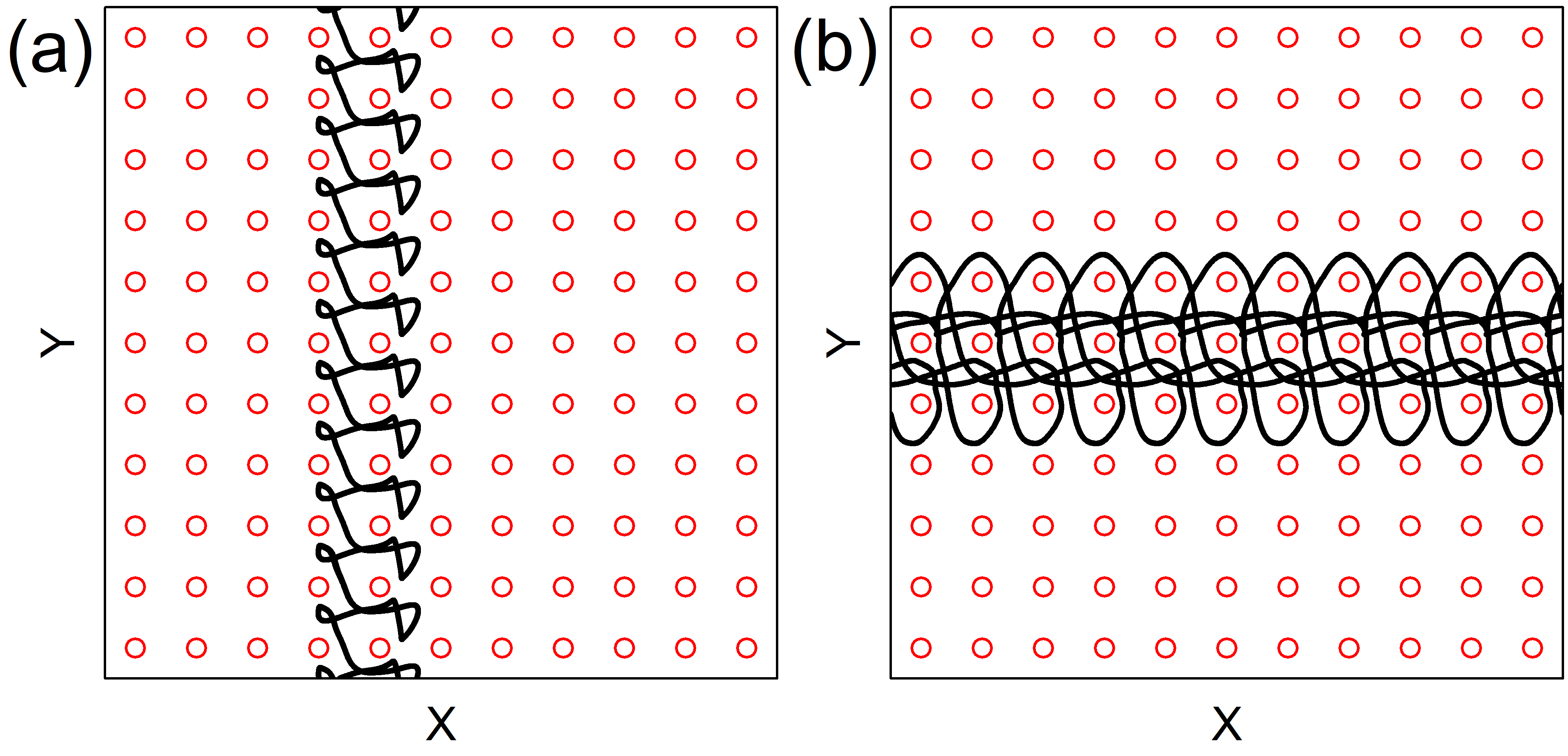
We first consider the case of a skyrmion subjected to a linear ac drive applied along the -direction, so that as shown in Fig. 1(a). In an overdamped system, a particle under such a drive would remain localized and would simply follow a one-dimensional trajectory along the -direction between the obstacles. A skyrmion with a finite Magnus term moves in a 2D orbit, as illustrated in Fig. 2 for a system with and . At in Fig. 2(a), the orbiting motion is localized. For a larger ac drive amplitude of in Fig. 2(b), the orbit size becomes large enough that the skyrmion collides with multiple obstacles, resulting in delocalization and diffusive chaotic motion but no net drift. In Fig. 2(c) at , the skyrmion has relocalized with a larger orbit that is similar in shape to the orbit in Fig. 2(a) but that spans two plaquettes during each ac drive cycle. The chaotic phase illustrated in Fig. 2(b) occurs at the transition between a skyrmion orbit that spans one plaquette and an orbit that spans two plaquettes. In each case the orbits are oriented at an angle to the linear ac drive as a result of the Magnus force. In the absence of the substrate, the skyrmion would move in a one-dimensional orbit at an angle of to the direction. As increases above , the skyrmion remains locked in the localized state of Fig. 2(b) until a transition occurs between localized motion spanning two plaquettes and the localized motion spanning three plaquettes that is illustrated in Fig. 2(e) at . A series of such localized phases occurs each time the skyrmion orbit spans an integer number of plaquettes, such as the state shown in Fig. 2(f) at . At the transitions between different localized states, delocalized or chaotic motion appears. In some cases there can also be fractional localization, as shown in Fig. 2(d) at where the skyrmion repeatedly switches between localized orbits that span two and three plaquettes.
In the overdamped limit, particles on a 2D substrate under a linear ac sinusoidal drive do not exhibit any kind of directed motion or ratchet effect; however, if two perpendicular ac drives are applied, the particle orbits become two-dimensional and directed motion can occur if the ac driving breaks a symmetry Tierno et al. (2007); Loehr et al. (2016); Reichhardt and Olson Reichhardt (2003); Speer et al. (2009); Platonov et al. (2015). In the skyrmion case, a linear ac drive in conjunction with the skyrmion-obstacle interactions produces a 2D orbit due to the Magnus force, as illustrated in Fig. 2(a). Since the orbit is chiral, temporal symmetry is broken and a ratchet effect can occur Reimann (2002). Under linear ac driving, we find only limited regimes where ratcheting of the skyrmion appears; however, this result demonstrates that even a single ac drive is sufficient to produce directed skyrmion motion on a symmetric substrate.
In Fig. 3 we plot and versus ac drive amplitude for the system in Fig. 2 with linear ac driving. In the localized states, , while in the delocalized states there are finite velocity fluctuations. Since the particle motion is diffusive, these fluctuations diminish in magnitude if the velocities are averaged over a longer period of time. At , there is ballistic motion in the negative direction and we find and , indicating that the skyrmion is translating by one lattice constant every two ac drive cycles, as illustrated in Fig. 2(d). The vertical dashed lines in Fig. 3 indicate the edges of the regions in which the skyrmion motion forms localized orbits spanning , 2, 3, or 4 plaquettes. We also observe smaller fractional localized phases in which the skyrmion spends two drive cycles in an orbit spanning plaquettes and one drive cycle in an orbit spanning plaquettes. These fractional localized states occur in the boundary regions between localized states, and are surrounded by delocalized phases.
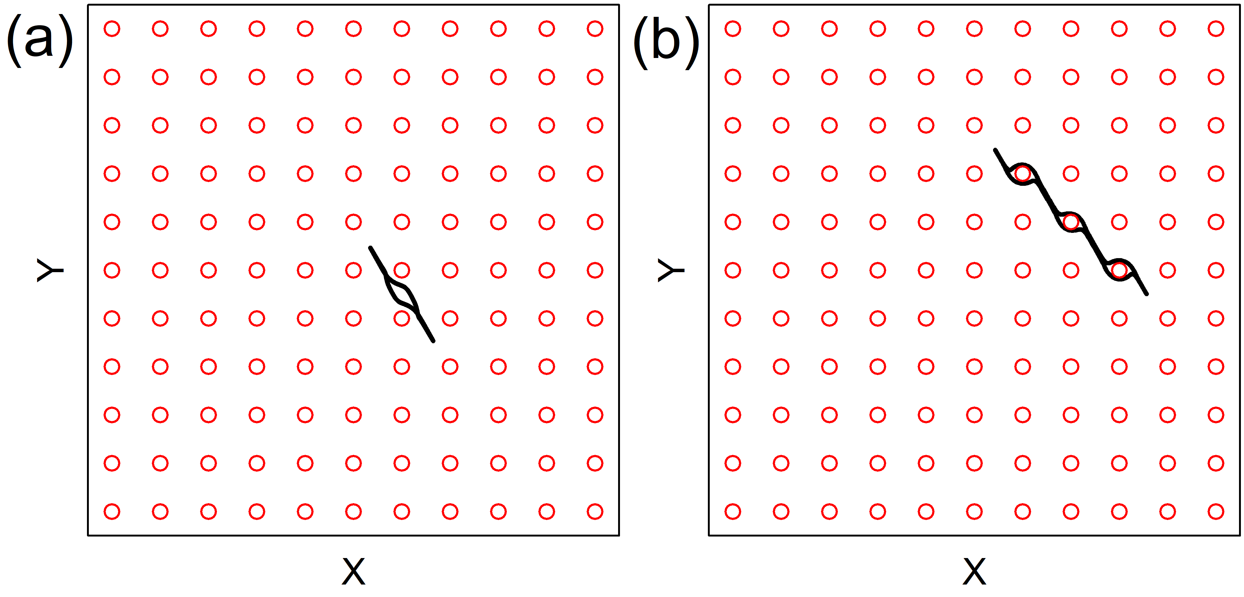
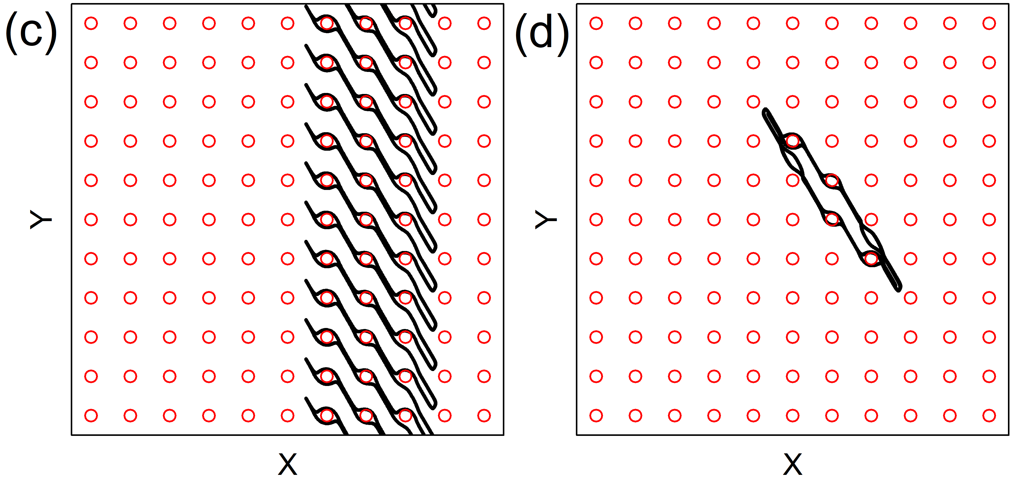
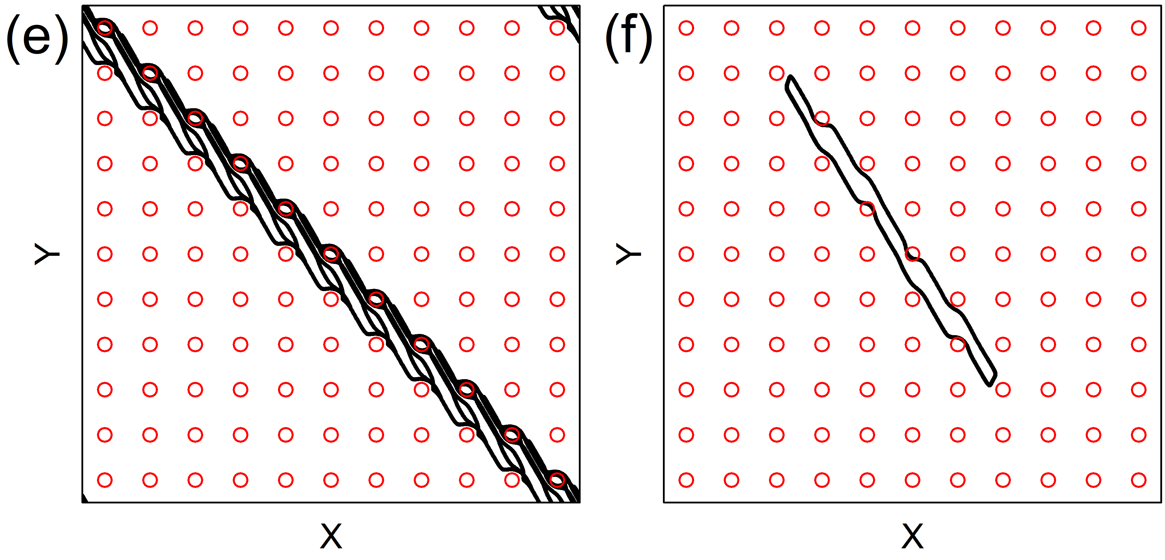
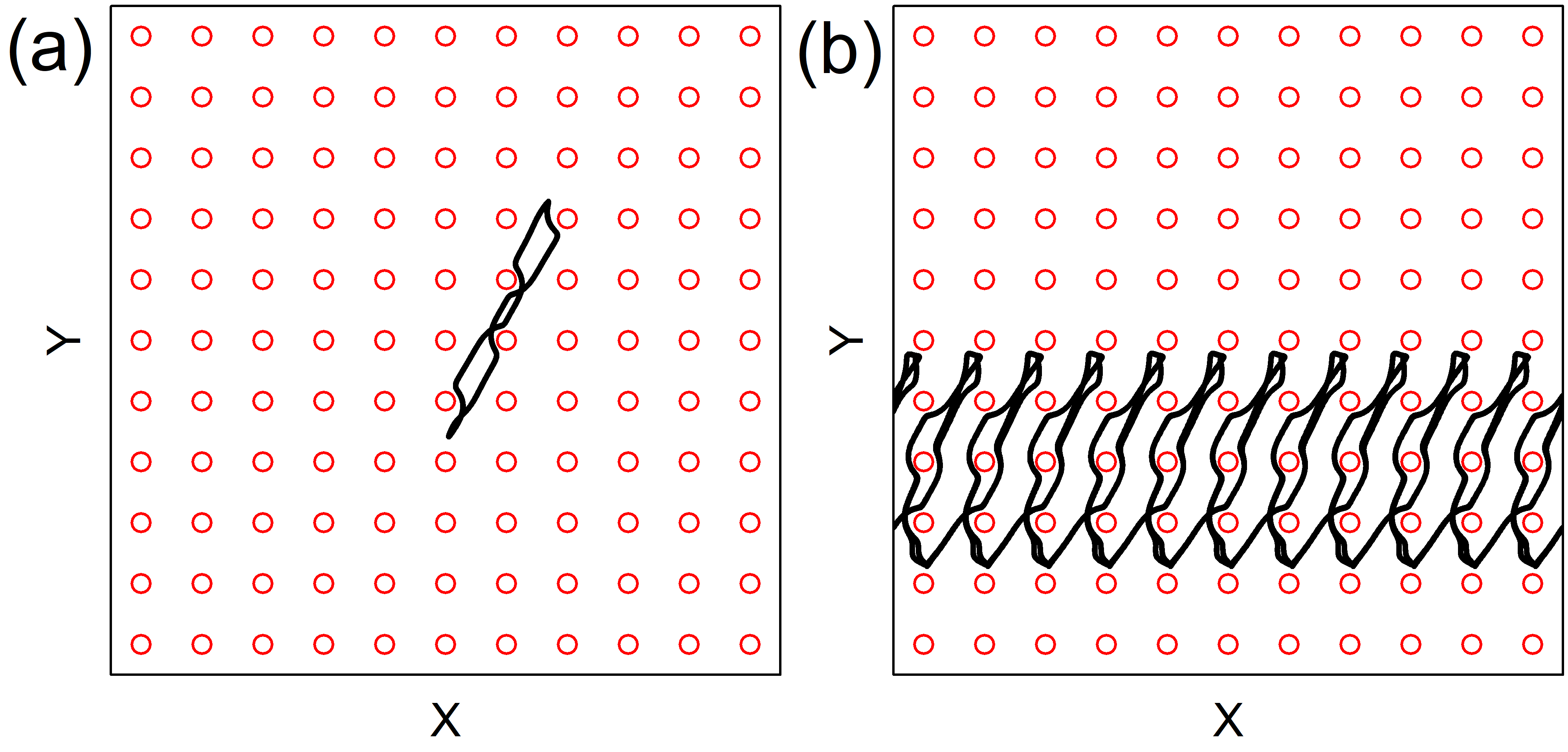
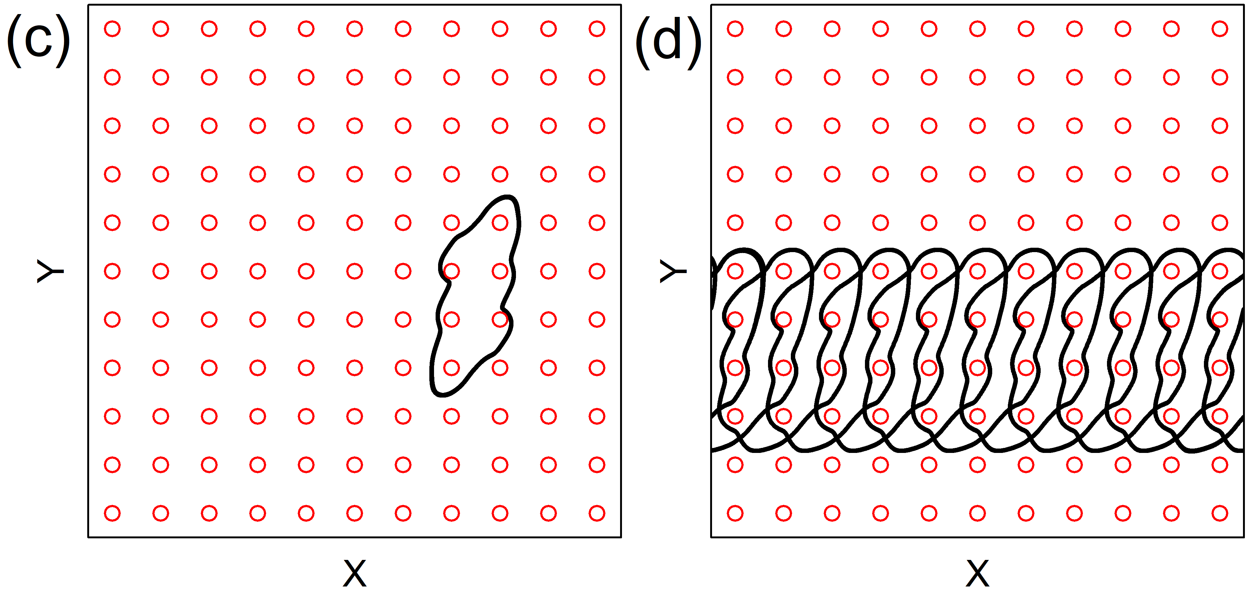
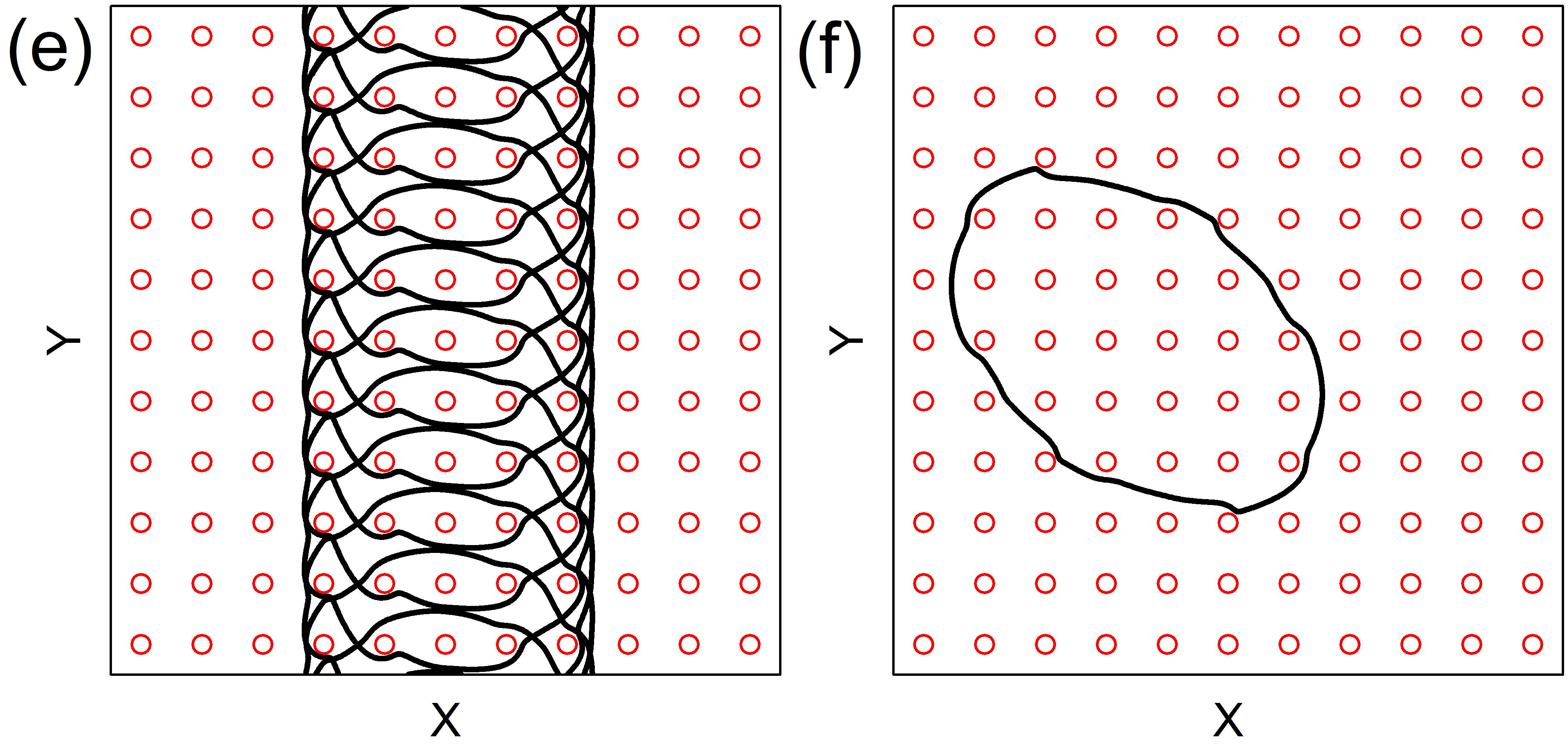
In Fig. 4(a-f) we plot representative skyrmion trajectories for a system with a linear ac drive and a larger Magnus component of . For and in Fig. 4(a) and (b), the orbit is localized at and plaquettes, respectively. The motion remains entirely within the interstitial region between obstacles for , but when , the skyrmion encircles the obstacles. At in Fig. 4(c), we find a translating orbit in which the skyrmion moves one lattice constant in the direction per ac drive cycle. When , the orbit is localized again but has a more complex shape, encircling four obstacles that do not fall along a one-dimensional line, as shown in Fig. 4(d). For in Fig. 4(e), there is a translating orbit where the skyrmion moves in the positive and negative directions at an angle of , translating by one lattice constant during every two ac drive cycles. In Fig. 4(f) at , there is an localized orbit that does not encircle any obstacles.
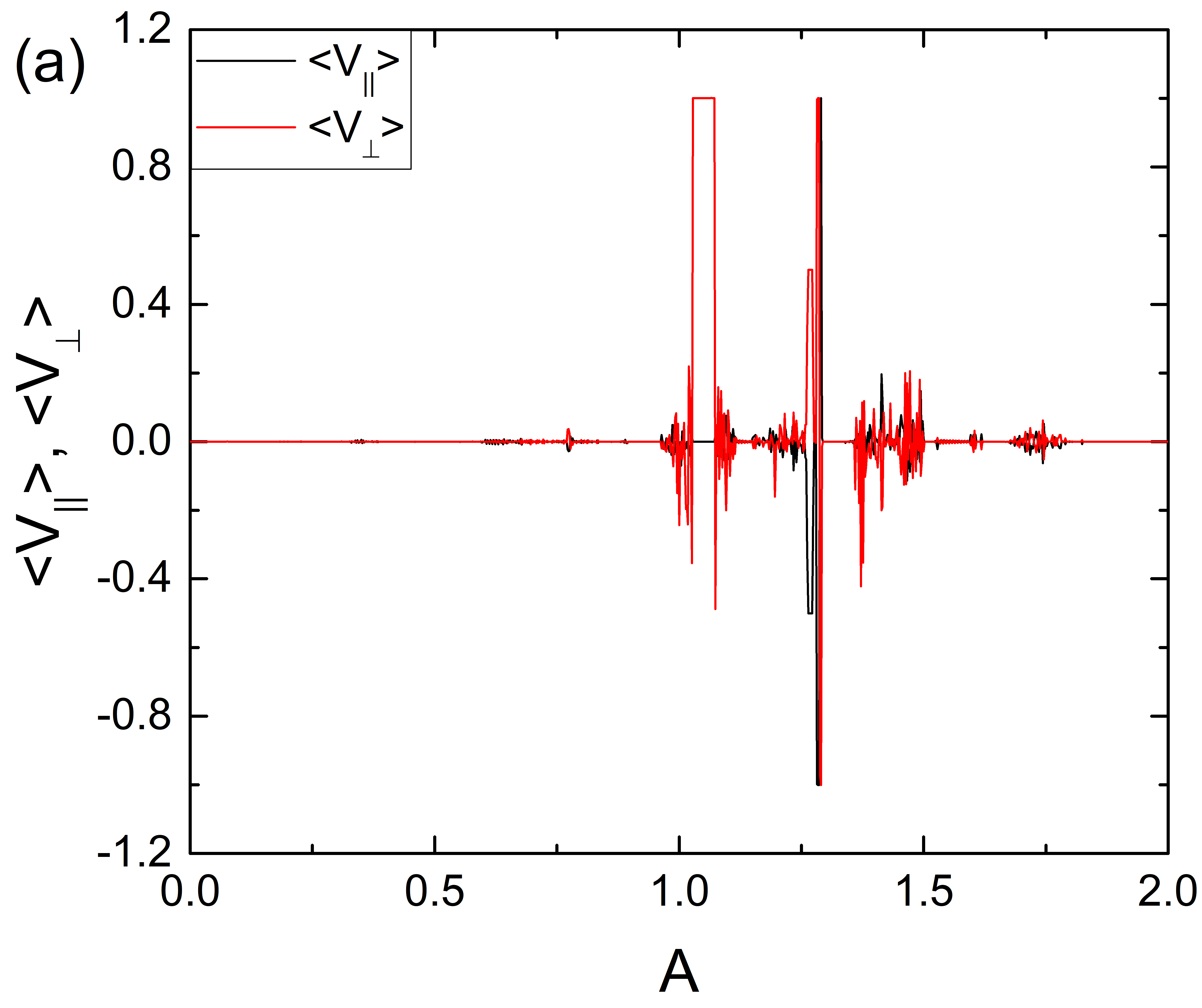
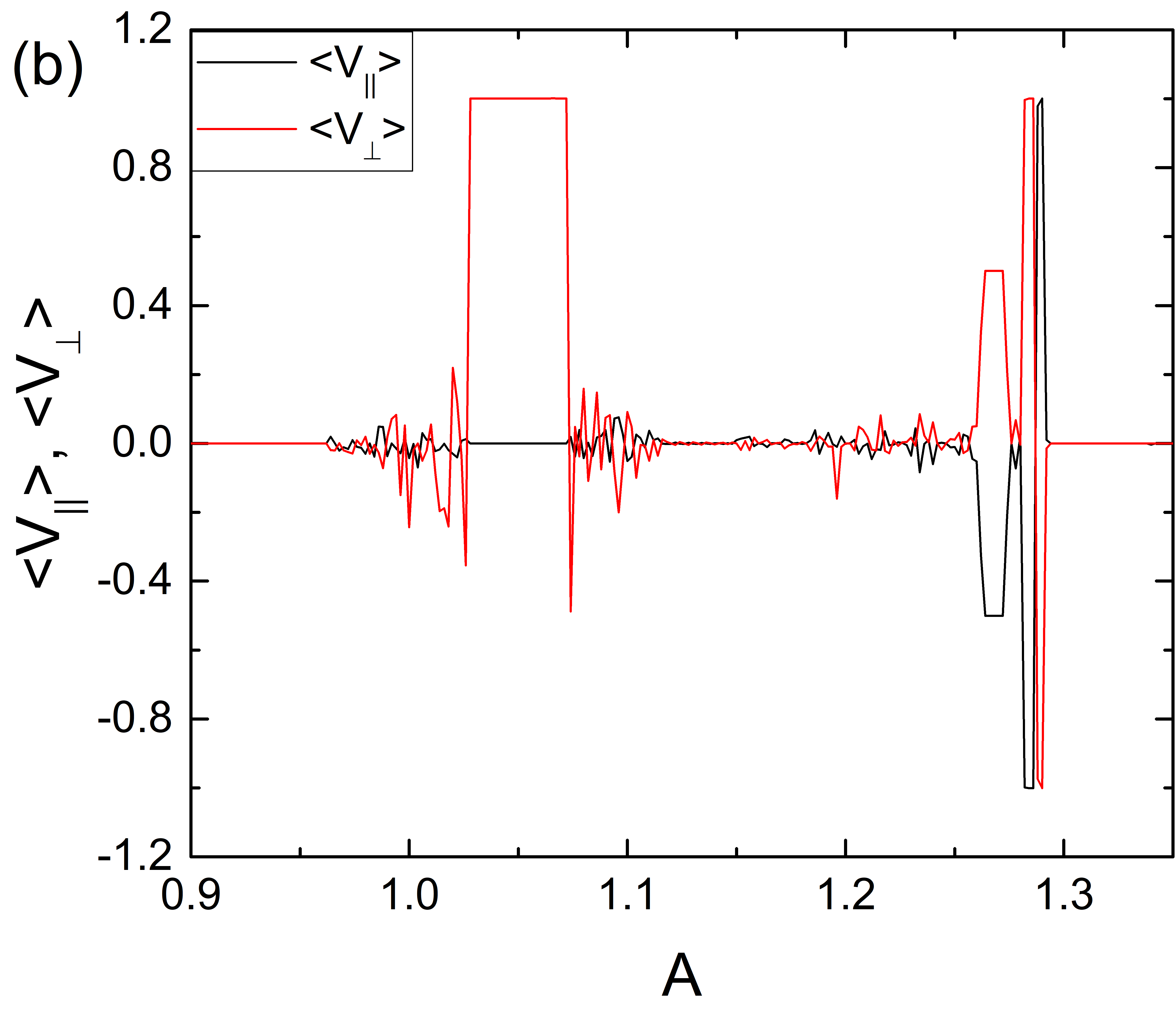
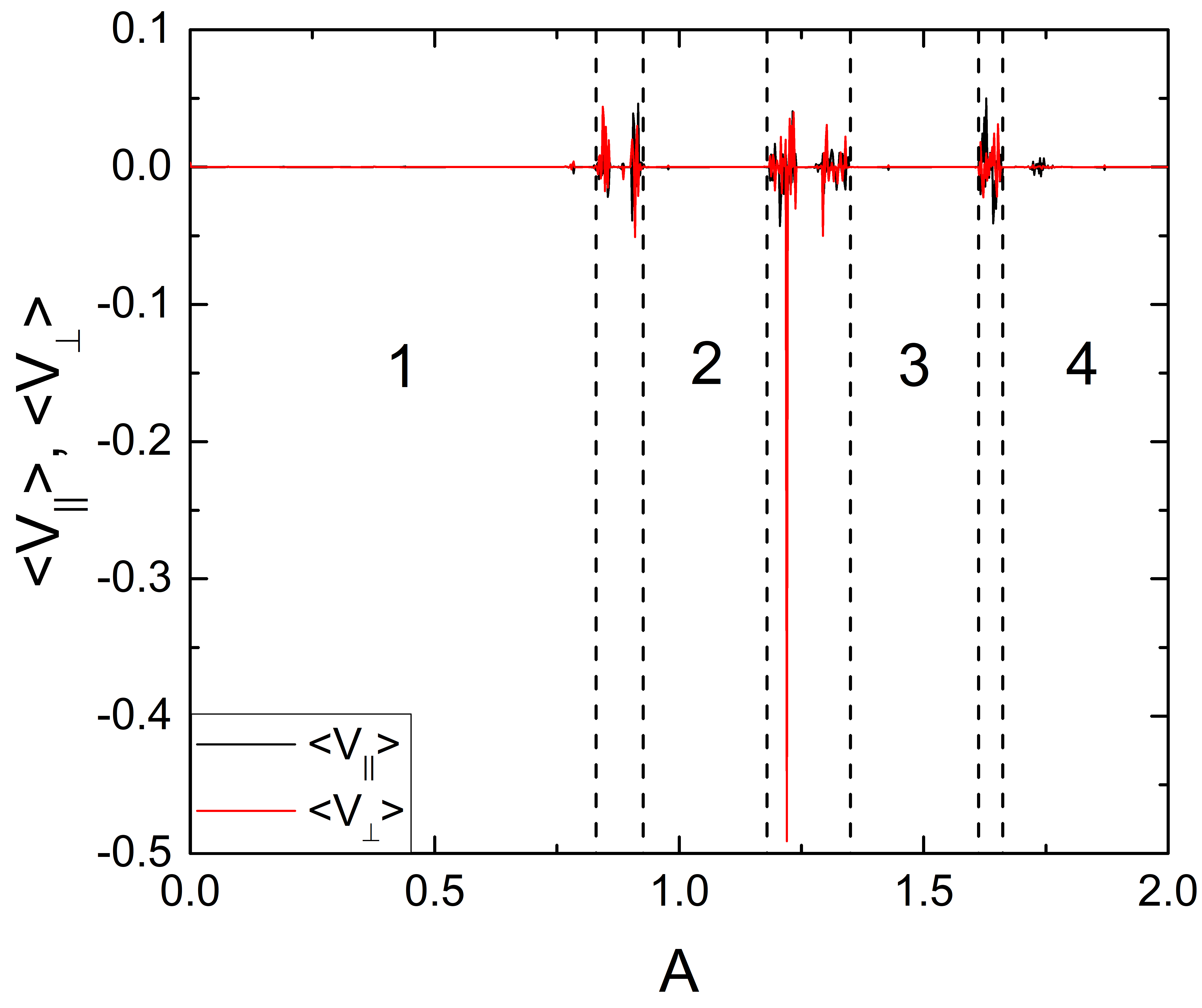
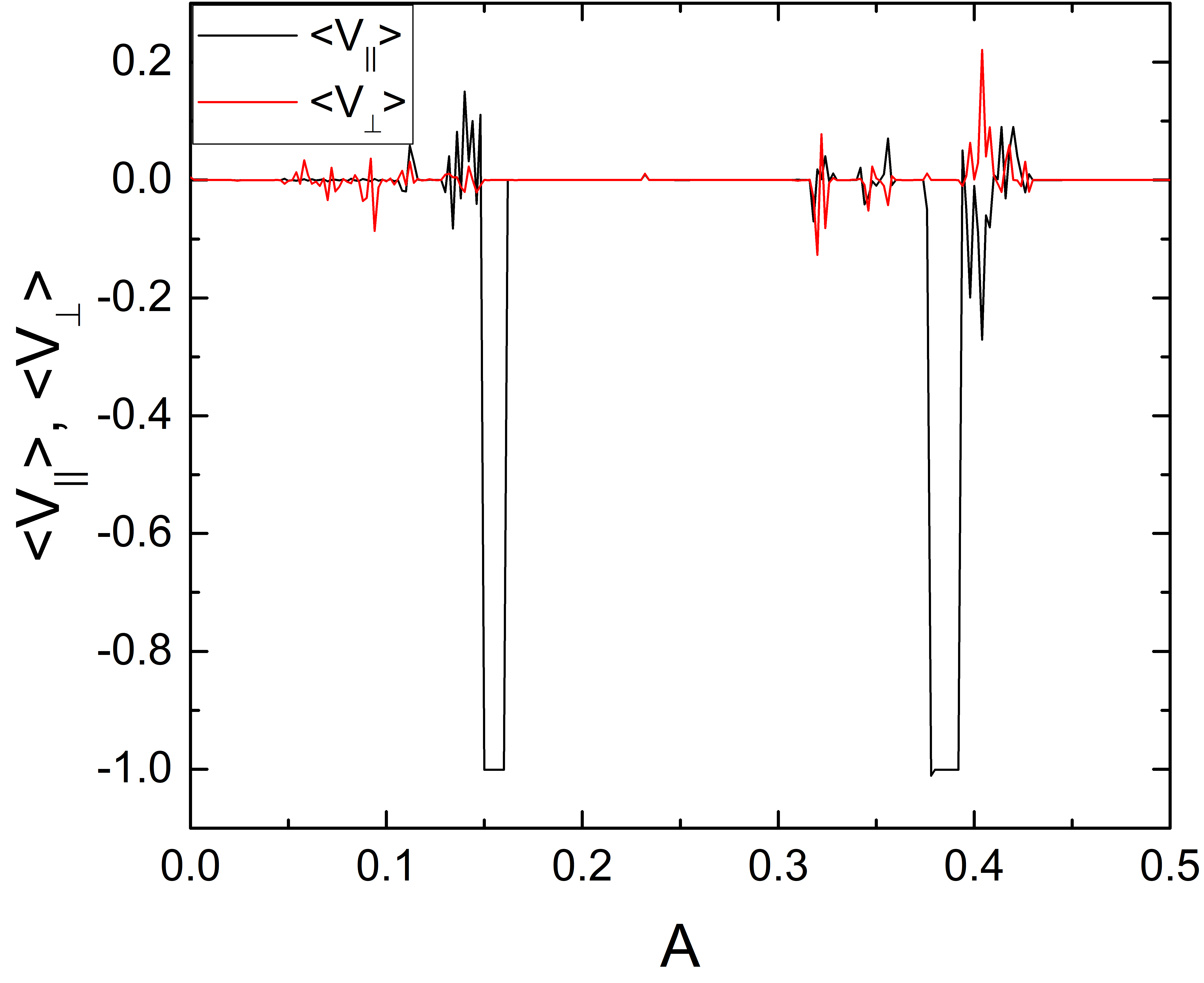
In Fig. 5(a) we plot and versus for the system in Fig. 4 showing the different regions of localized and translating orbits. Figure 5(b) is a blowup of Fig. 5(a) over the range . Localized orbits appear when , followed by a window of delocalized orbits for . The translating orbit illustrated in Fig. 4(c) corresponds to the plateau of positive extending from to . As increases, the system enters another regime of chaotic motion. When , a translating state appears with motion along , where the skyrmion moves one lattice constant in the positive and negative directions every two ac drive cycles. Here the velocities plateau with . This is followed by a small localized region, and then at by a second regime of translation, where the skyrmion moves one lattice constant in the positive and negative directions during every ac drive cycle. At the translation changes direction and the skyrmion moves one lattice constant in the positive and negative directions during every ac drive cycle, as illustrated in Fig. 4(e). Finally the motion becomes localized again above as shown in Fig. 4(f). In general, as the Magnus term increases, a greater variety of distinct localized and translating orbits appear. The translating orbits are generally along either the or directions or at a angle, since these are the most prominent symmetry directions of the obstacle lattice.
For higher values of , we find delocalized phases or chaotic orbits that exhibit an average drift. In Fig. 6 we plot representative trajectories in a system with . At in Fig. 6(a), there is a localized 1D orbit oriented at nearly to the driving direction. For , the orbit is delocalized or chaotic but has a net drift in the negative direction and a smaller net drift in the negative direction, as shown in Fig. 6(b). When , as in Fig. 6(c), we find a translating orbit with gradual motion by one lattice constant in the positive direction, where the skyrmion spends many ac cycles at each location before stepping to the next location. In Fig. 6(d) at , a localized orbit appears that spans four plaquettes and encircles the two obstacles at the top and bottom of the orbit. In Fig. 7 we plot and versus to illustrate the transitions between the different states. The motion is localized for and , while at intermediate values of , various fluctuating and localized regions occur.
III.2 Circular ac Drive with
We next consider the case of circular ac driving by applying two ac drives that are perpendicular to each other and out of phase. In the overdamped limit, a symmetric substrate does not produce any directed motion when the frequencies and amplitudes of the two ac drives are identical; however, if the amplitudes or frequencies differ, spatial asymmetry can appear in the particle orbit, leading to directed motion Tierno et al. (2007); Loehr et al. (2016); Reichhardt and Olson Reichhardt (2003); Speer et al. (2009). For and , if we set we find no ratchet effect and the dynamics are the same as those found in vortex pinball systems, with transitions between localized and delocalized orbits as the ac drive amplitude increases Reichhardt and Olson (2002).
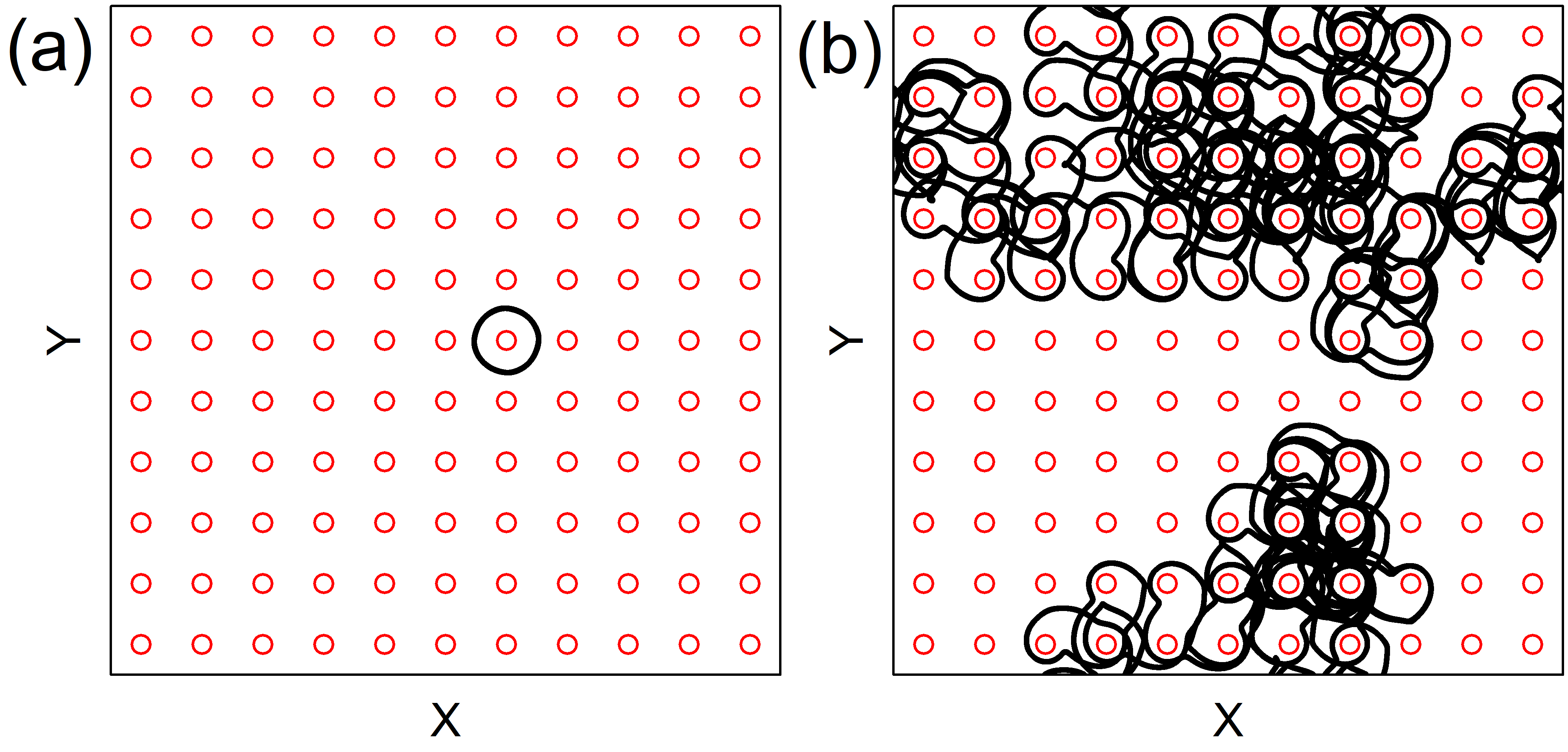
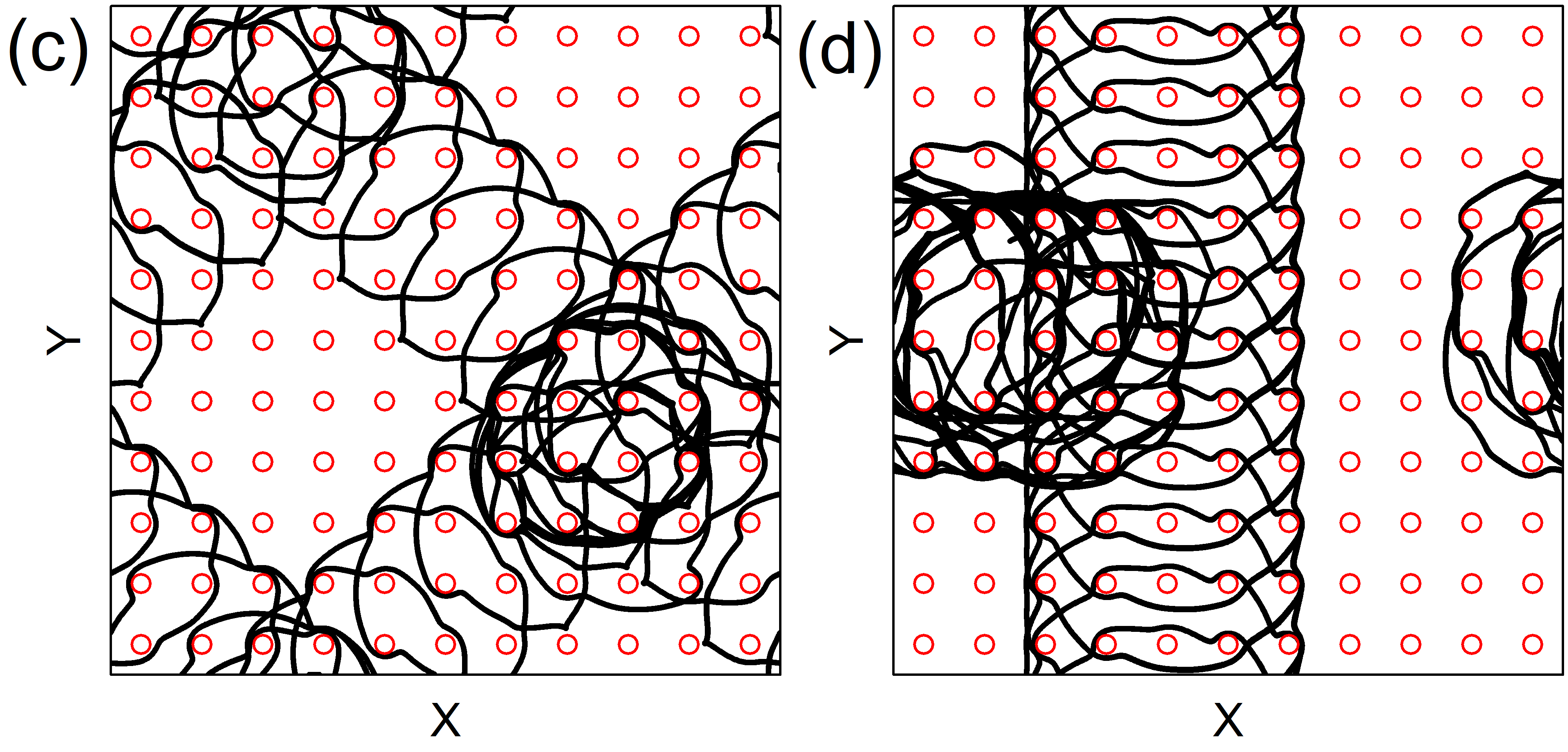
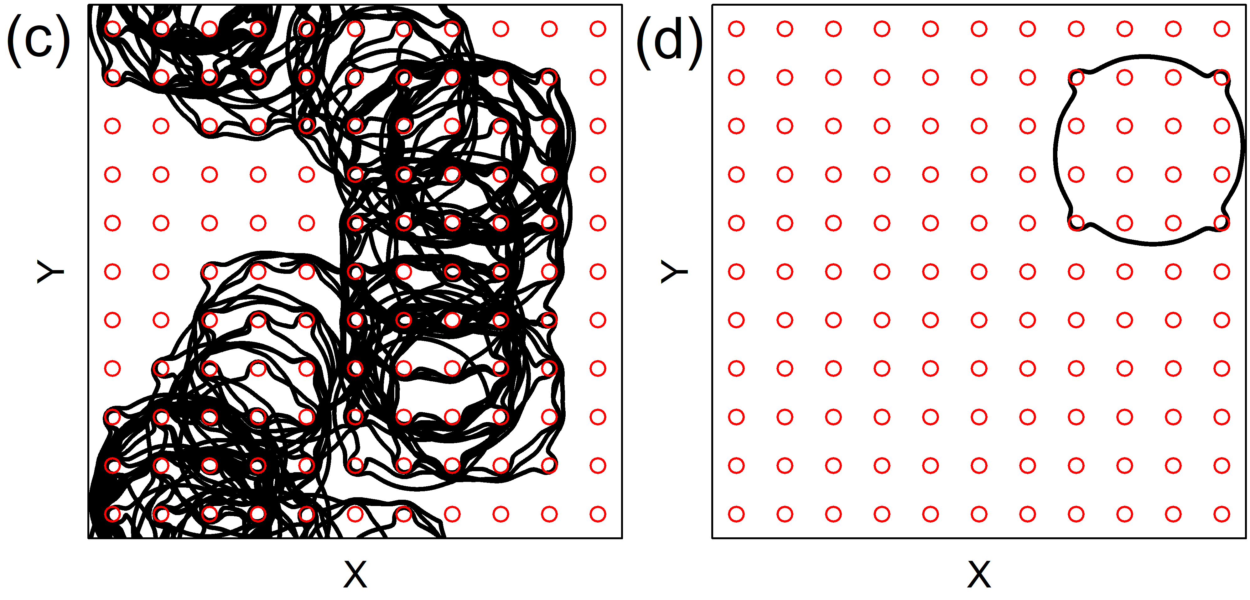
In Fig. 8 we show skyrmion trajectories in a system with circular ac driving at for and . At in Fig. 8(a), the skyrmion forms a localized orbit that encircles one obstacle. In Fig. 8(b) at , we find a translating orbit in which the skyrmion spirals around two obstacles per ac drive cycle and moves in the negative -direction. Figure 8(c) shows a localized orbit at where the skyrmion encircles four obstacles, while the localized orbit at in and Fig. 8(d) has no net drift but exhibits diffusive motion over long time scales. At in Fig. 8(e), there is a translating orbit in which the skyrmion moves one lattice constant in the positive direction during every ac drive cycle, while at in Fig. 8(f), the skyrmion follows a localized orbit encircling 21 obstacles.
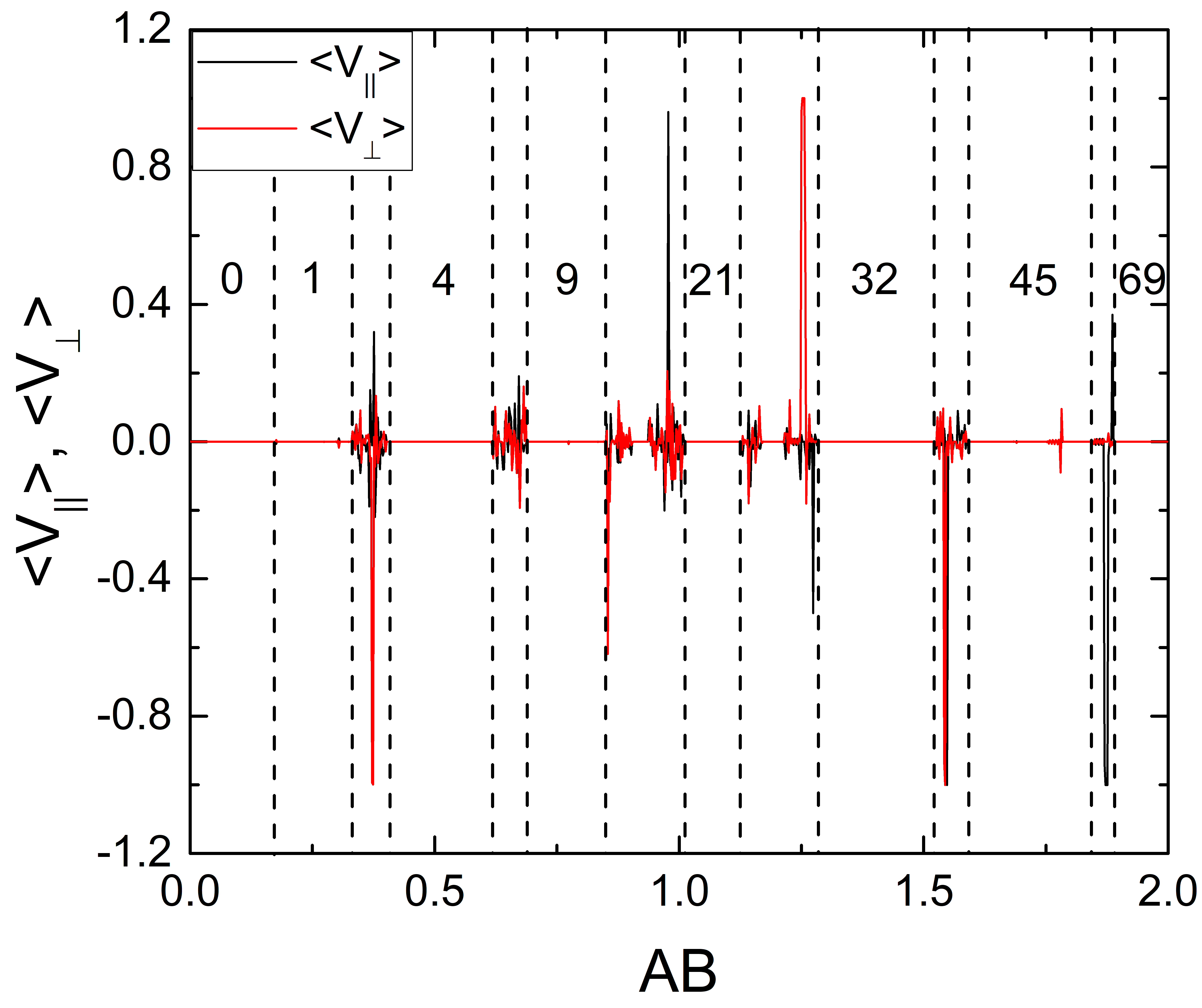
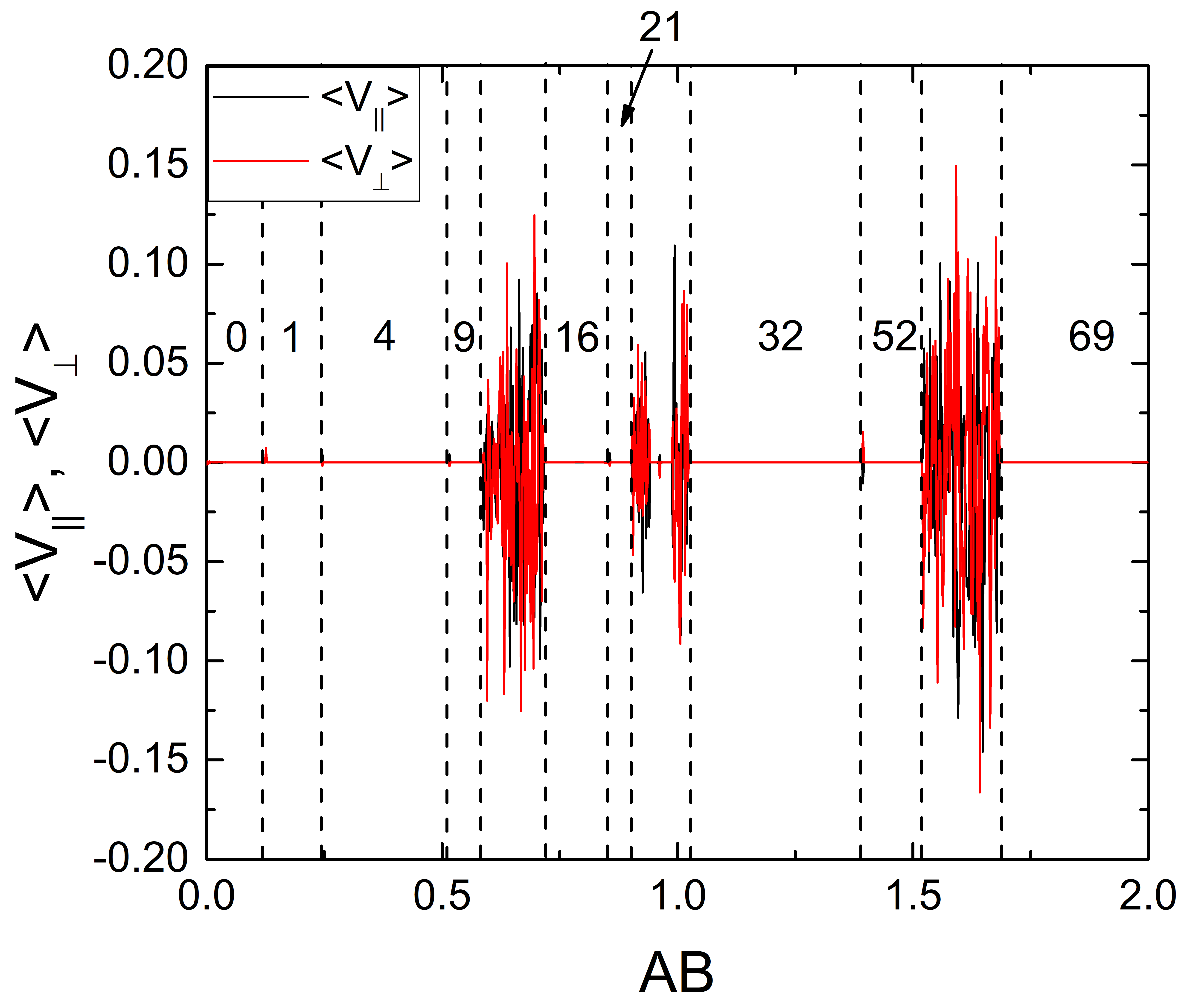
Similar orbits appear at higher ac amplitudes. The localized orbit of Fig. 8(f) persists over the range , while an orbit encircling 26 obstacles appears for . At higher we find additional localized orbits in which the skyrmion encircles , 45, or obstacles. In general, stable localized orbits appear close to drives where the skyrmion can perfectly encircle obstacles; however, due to the square symmetry of the obstacle array, the orbits can deviate from purely circular states so that, for example, the stable orbit encircles rather than obstacles. In Fig. 9 we plot and versus for the system in Fig. 8, highlighting the locations of some of the localized phases where , 1, 4, 9, 21, 32, 58, and obstacles are encircled. Several delocalized regions, including translating orbits and reversals in the translation direction, appear in between the localized regimes.
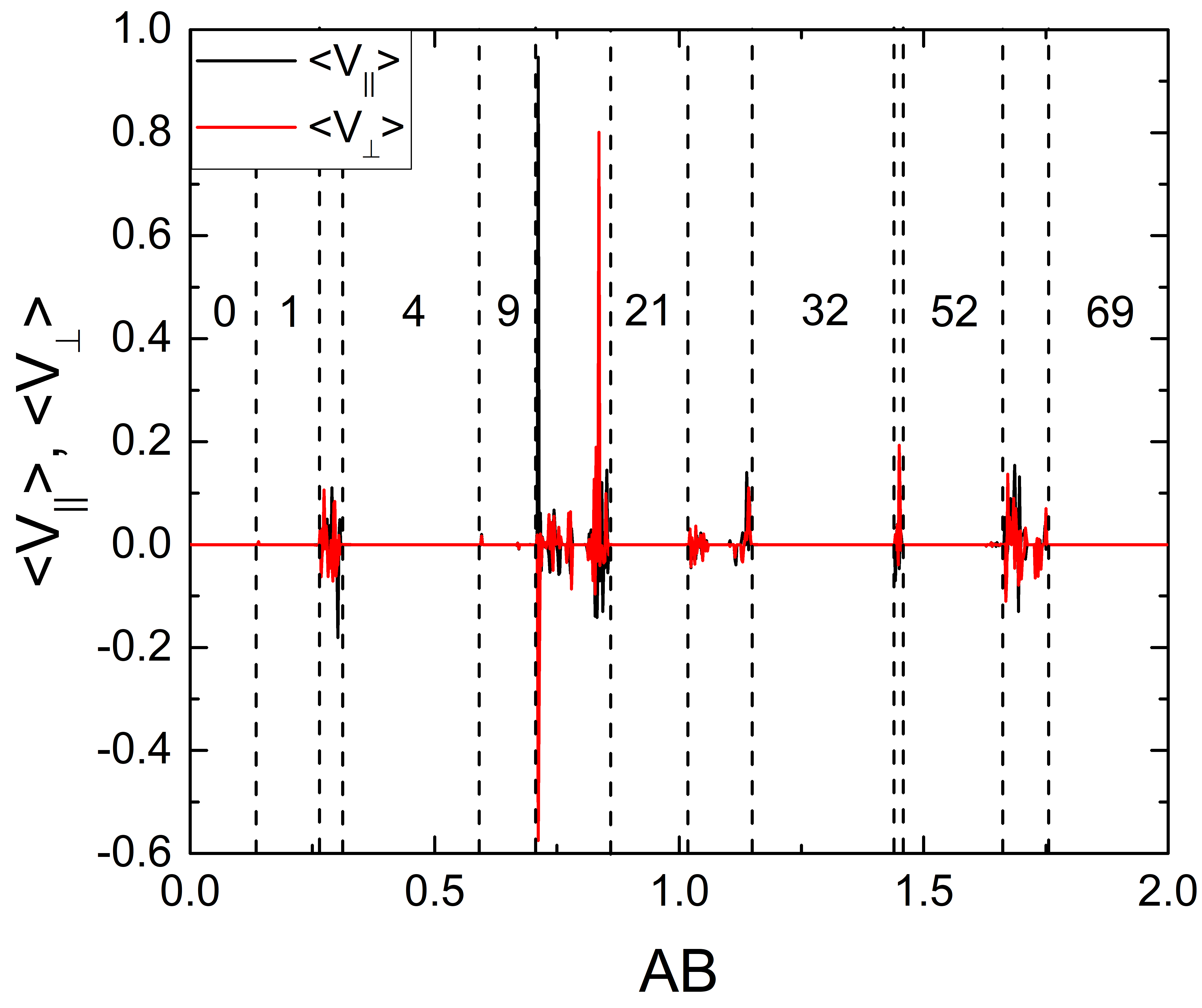
In Fig. 10 we plot the skyrmion trajectories and obstacle locations for a system with and circular driving with and . For in Fig. 10(a), the skyrmion forms a localized orbit encircling one obstacle, while at in Fig. 10(b), the motion is diffusive or chaotic. At , Fig. 10(c) shows that there is a translating orbit that jumps between motion along and . This orbit produces no net directed motion, but at short times the behavior is superdiffusive. In Fig. 10(d) at , the skyrmion locks into an orbit that translates along the direction. In Fig. 11 we plot and versus for the system in Fig. 10, with vertical lines indicating the regions where localized orbits encircle , 1, 4, 9, 21, 32, 52, and obstacles. In between the and regimes, we find two regions of directed motion. Just above the regime, the skyrmion translates in the positive and negative directions along , while just below the regime, the skyrmion translates in the positive -direction. There is also a smaller region between these two translating phases where the system forms a localized state encircling obstacles.
As we increase in the circular drive system with , we find fewer translating orbits and wider regions of delocalized orbits. In Fig. 12 we illustrate skyrmion trajectories in a system with . At in Fig. 12(a), there is a localized orbit encircling one obstacle. In Fig. 12(b) at , the localized orbit encircles four obstacles. The delocalized orbit at appears in Fig. 12(c). At in Fig. 12(d), the localized orbit encircles 16 obstacles. In Fig. 13 we plot and versus for the system in Fig. 12, where the vertical lines indicate the windows of localized phases in which the skyrmion encircles 0, 1, 4, 9, 16, 32, 52, or obstacles. There are several chaotic regimes but no regions of directed flow.
III.3 Circular ac Drives with
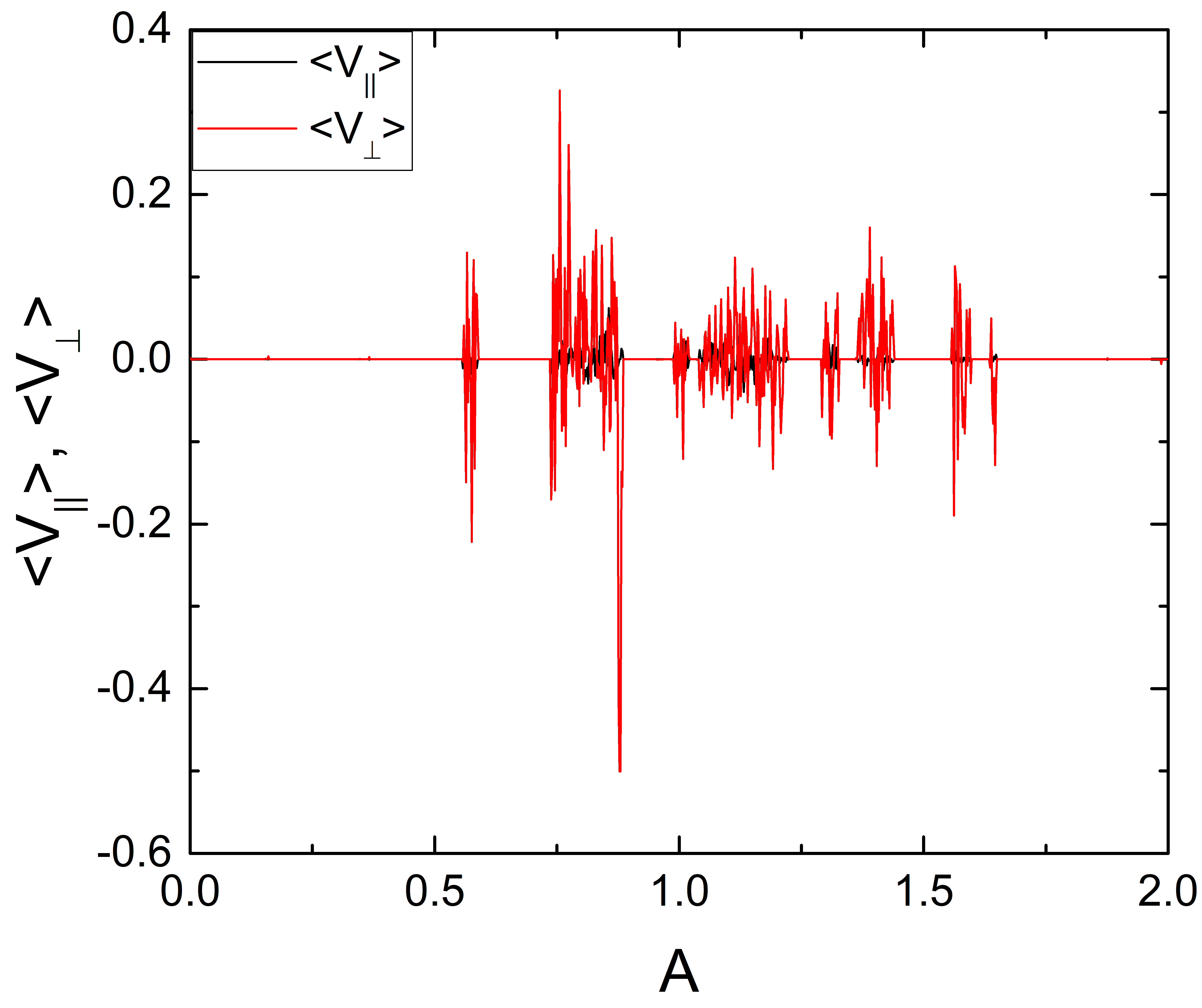
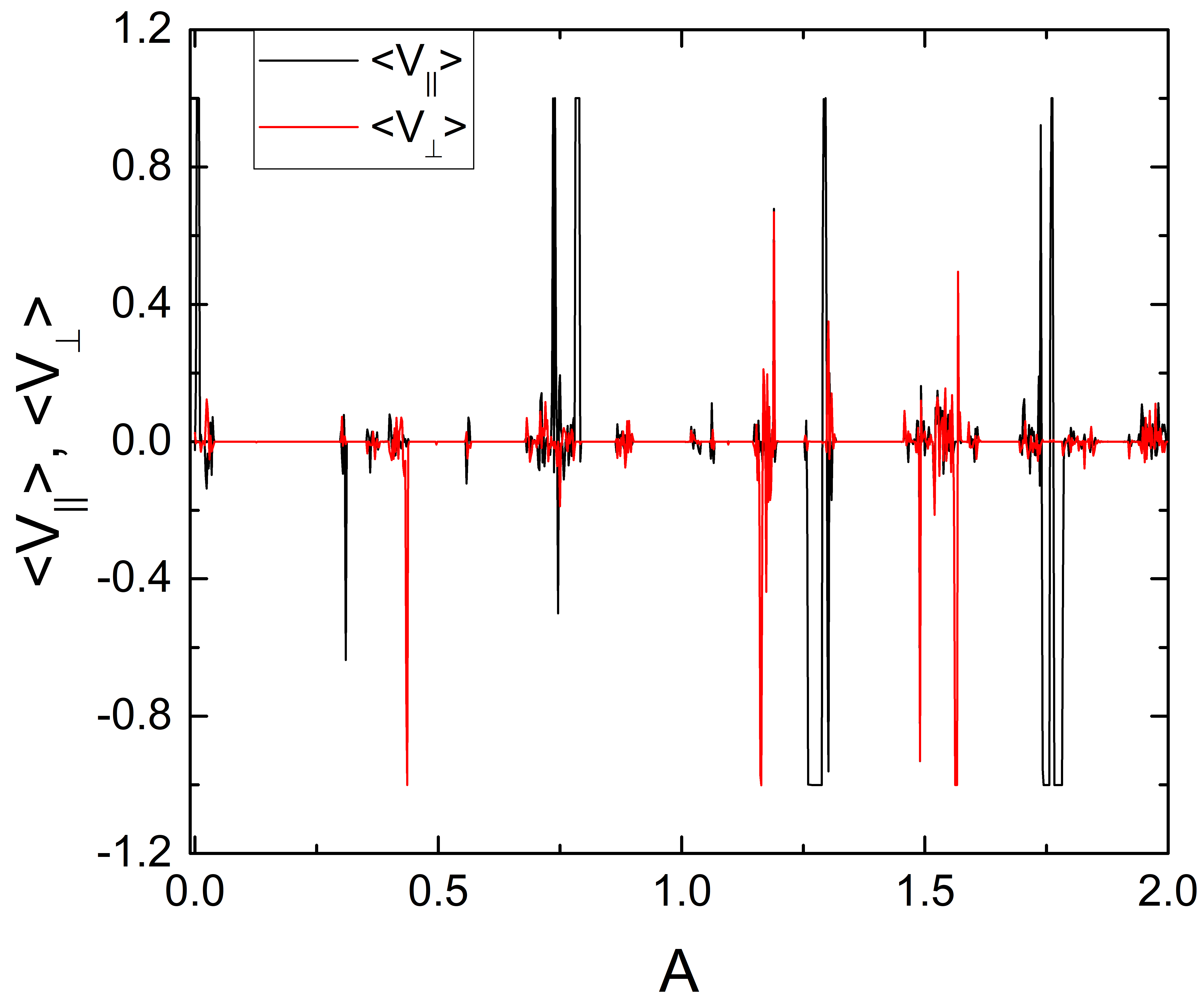
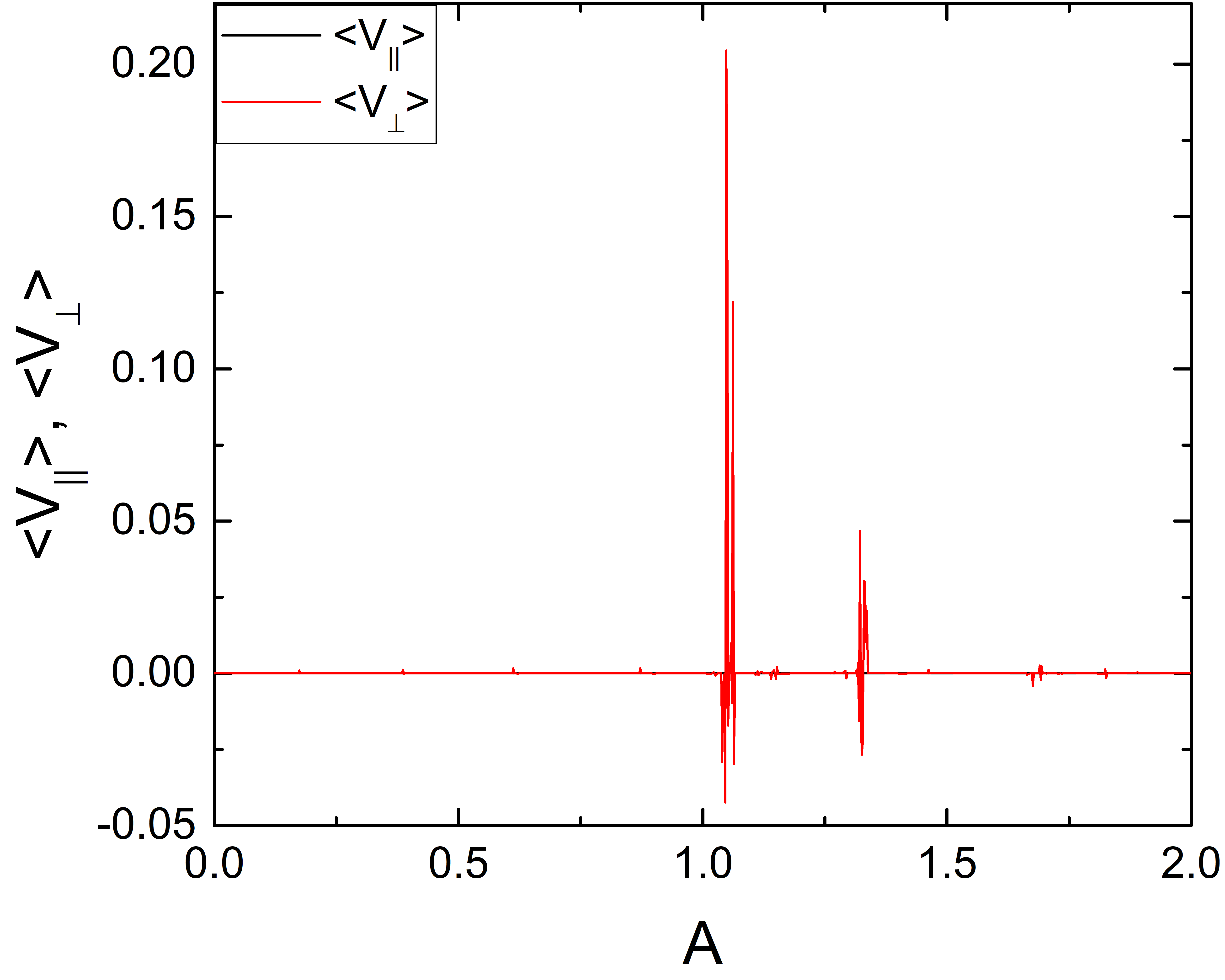
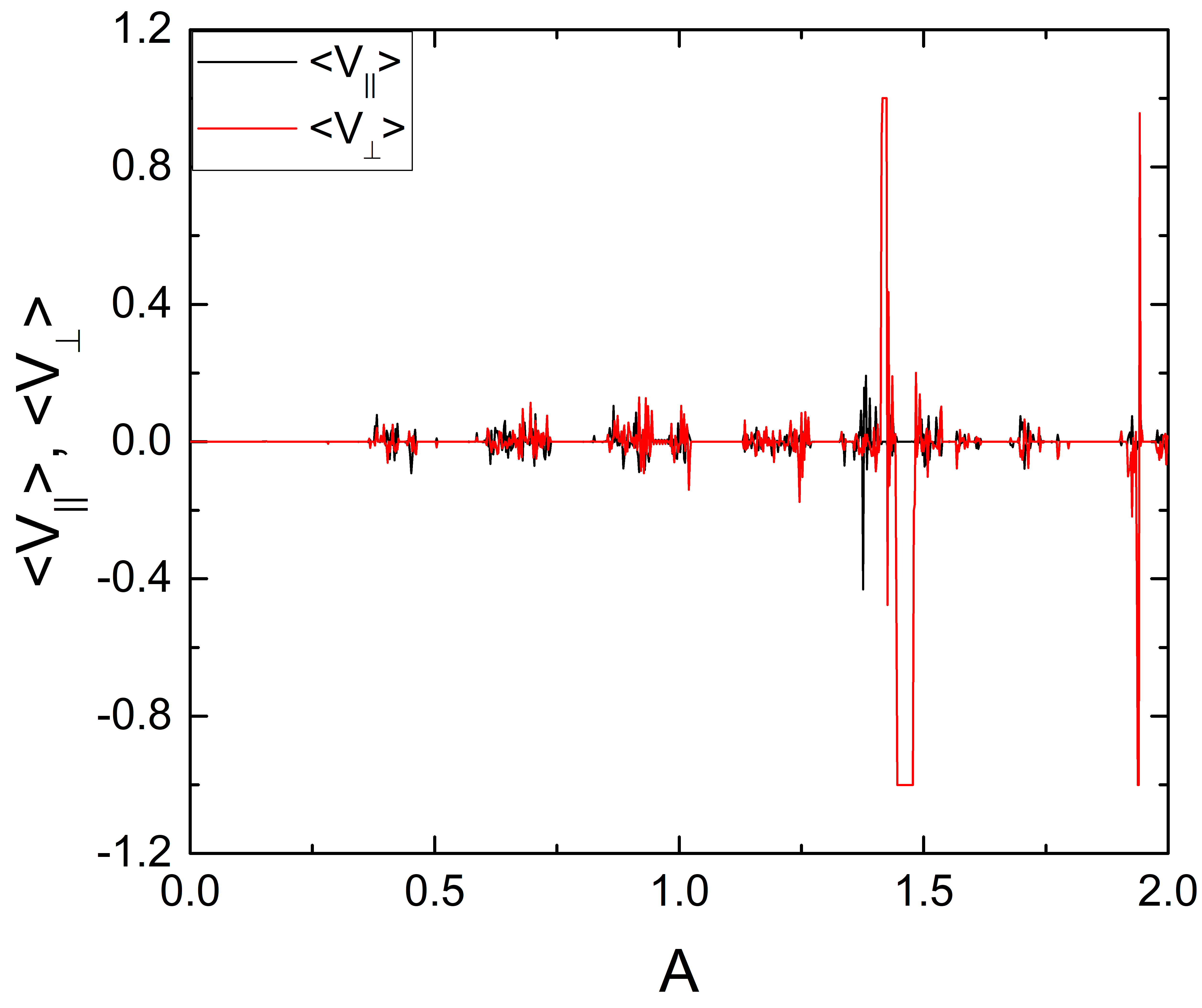
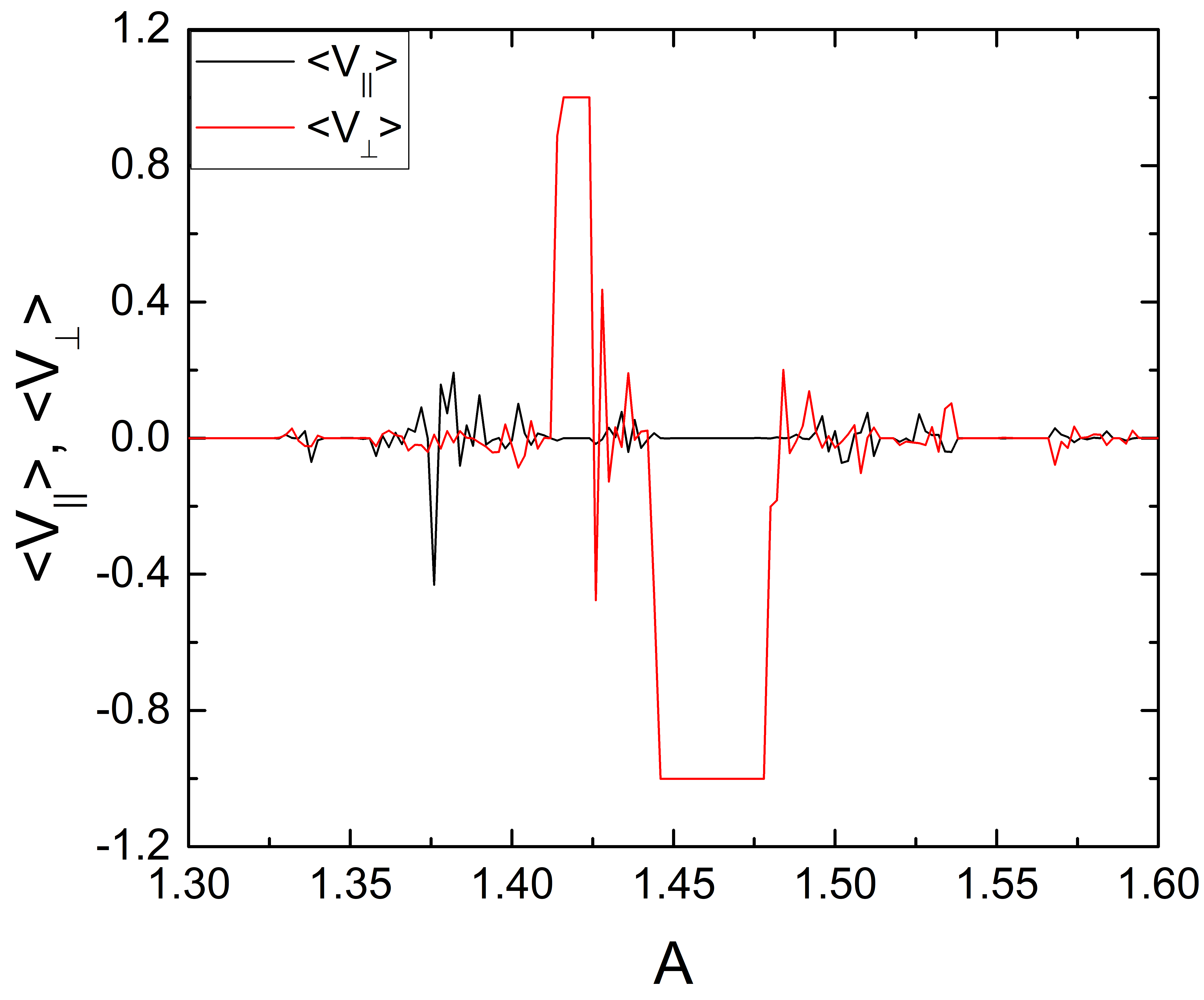
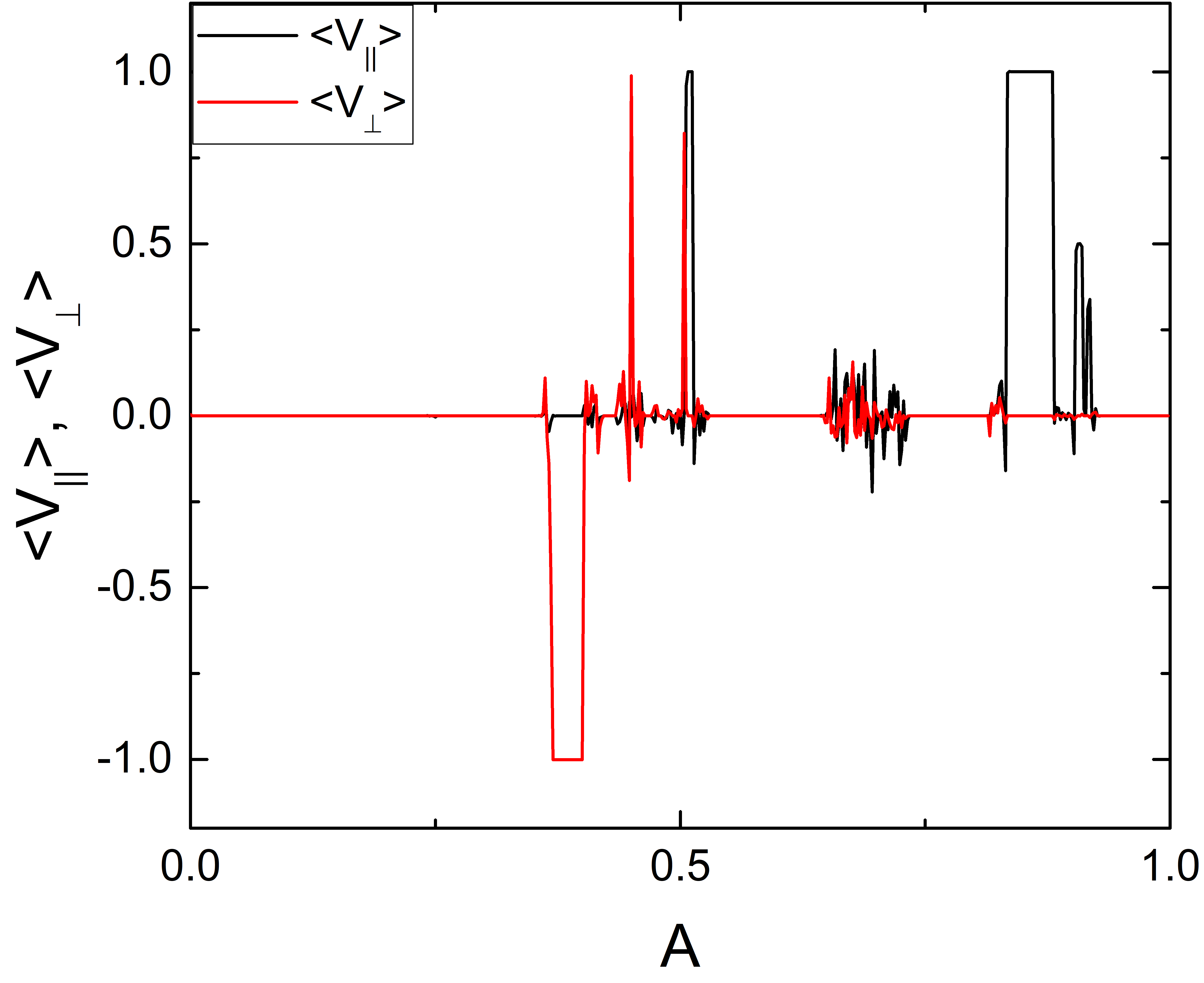
The number of translating orbits produced by a circular ac drive can be increased by setting so that the drive amplitude is different in the and directions. In Fig. 14 we plot and versus in a sample with , where we have fixed . Here there are there six regimes of directed motion. Two of these regimes are highlighted in Fig. 14(b), which is a blow up of Fig. 14(a) over the range . The minima in correspond to translation of the skyrmion in the negative direction by one lattice constant every ac drive cycle. Near , we find fractional translation in which the skyrmion moves one lattice constant in the negative direction every four ac drive cycles, closely followed by a second fractional translation phase where the skyrmion moves one lattice constant in the positive direction every three ac drive cycles. Near , there are two additional phases in which the skyrmion moves one lattice constant in either the negative direction or the positive direction every ac drive cycle. There are several additional translating orbits near .
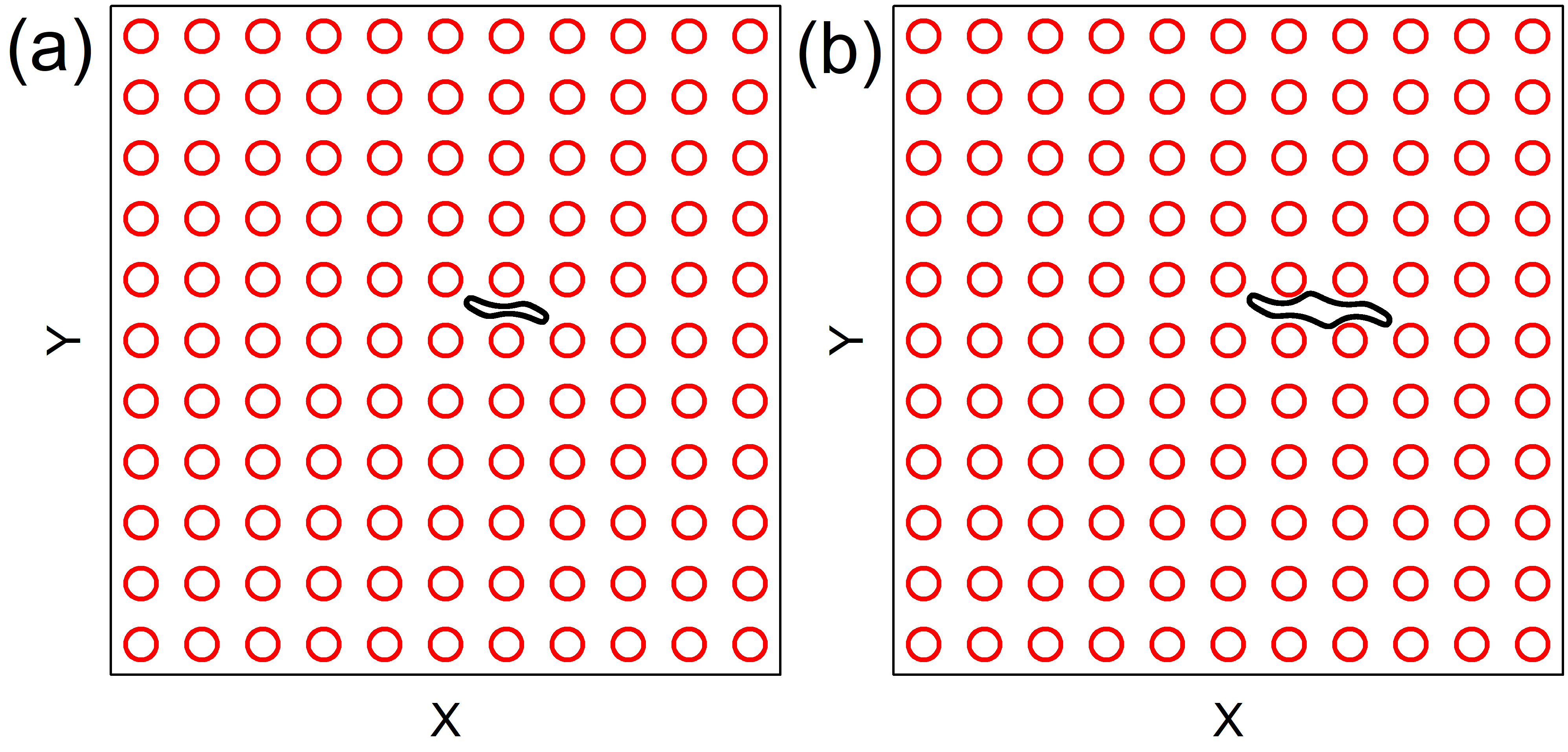
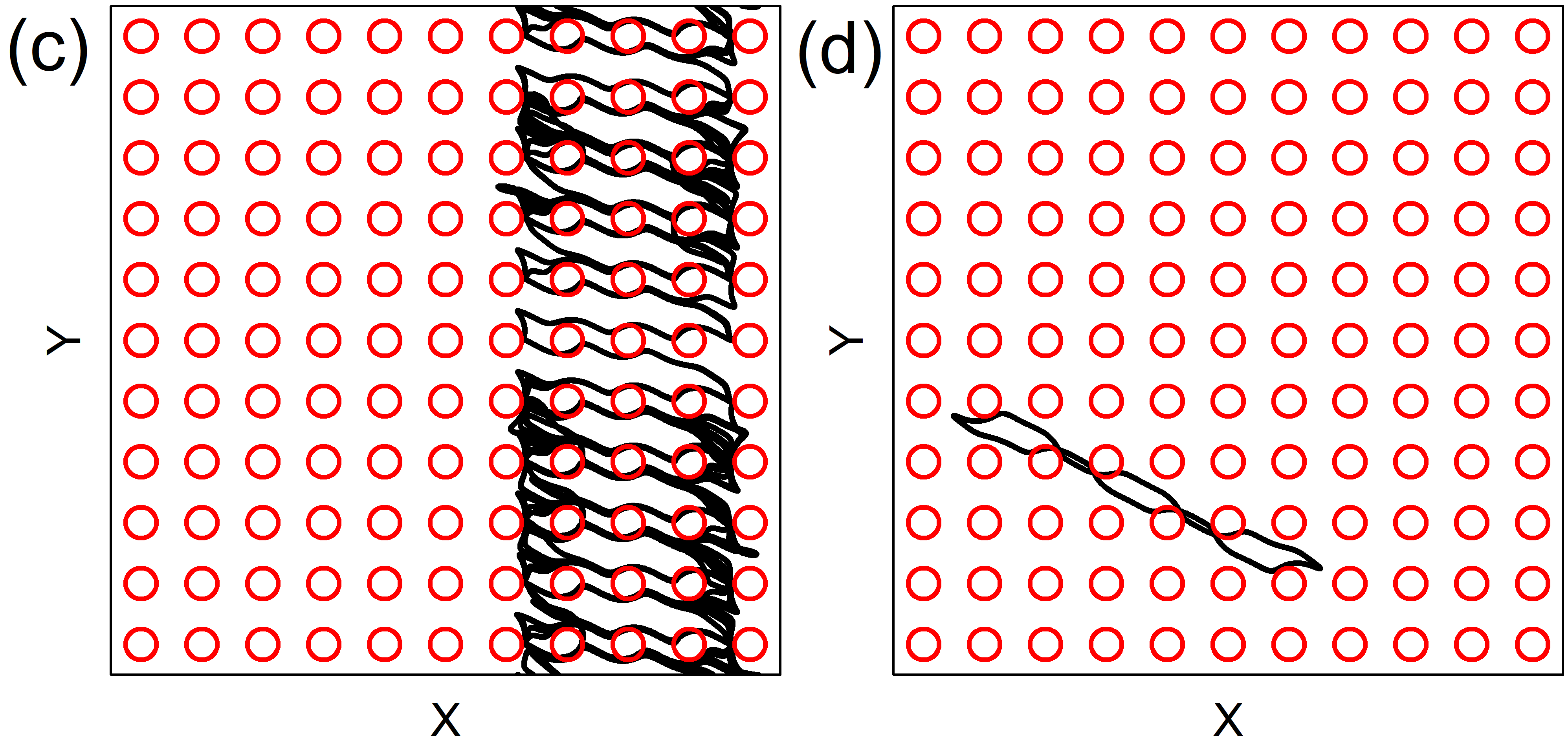
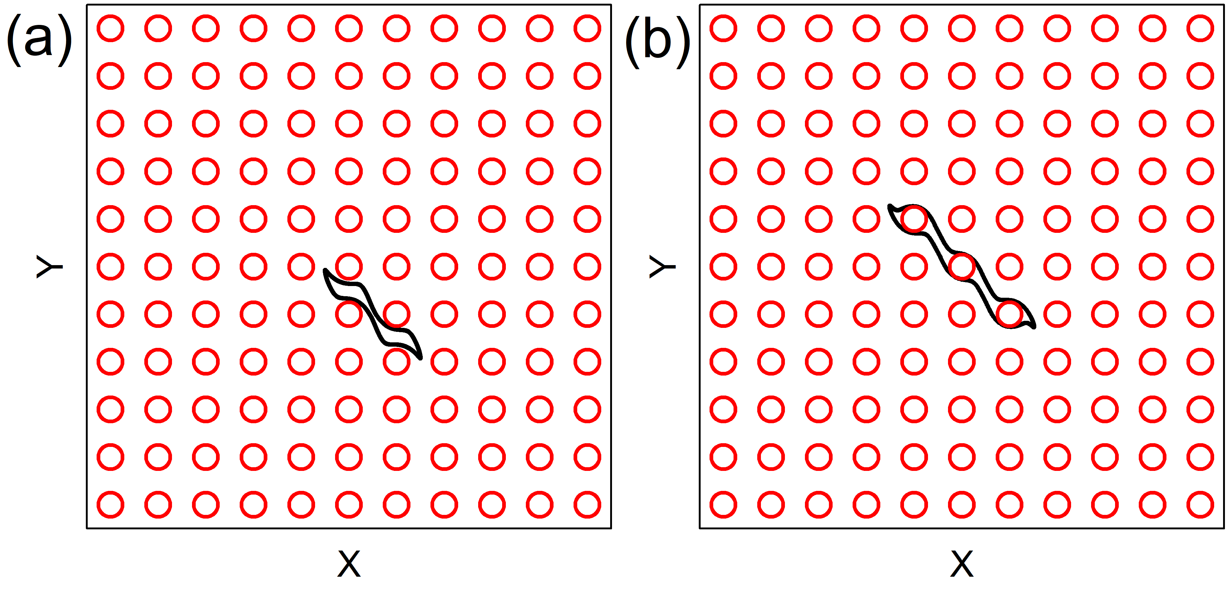
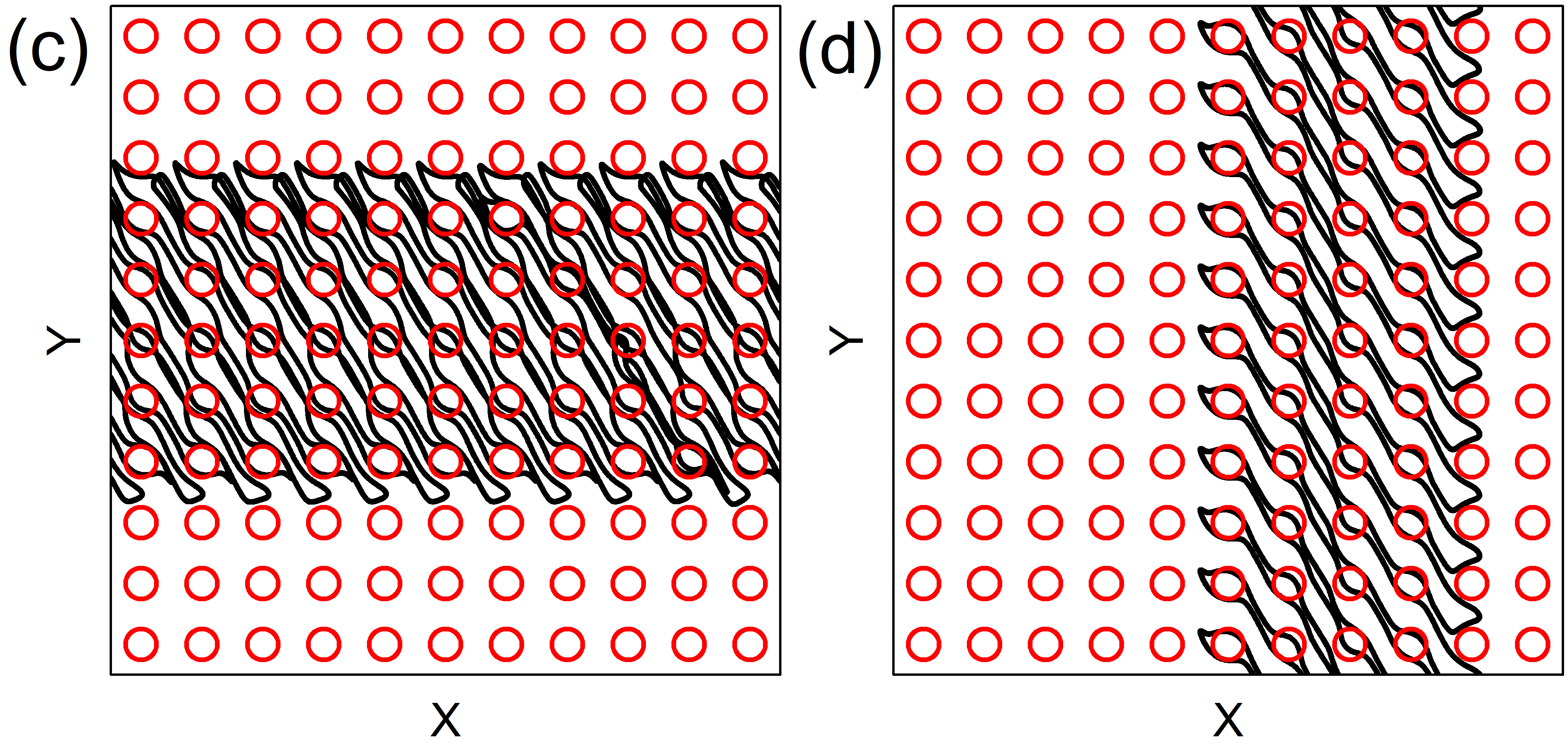
In Fig. 15 we illustrate the skyrmion trajectories for the system in Fig. 14. Figure 15(a) shows the localized state at , where the skyrmion moves between three obstacles. At in Fig. 15(b), there is a translating orbit in which the skyrmion moves one lattice constant in the negative direction during every ac drive cycle. This corresponds to the first translating regime shown in Fig. 14(b). In Fig. 15(c) we plot the localized orbit at , where the skyrmion orbit is asymmetric and encircles six obstacles. Figure 15(d) shows the second ratcheting orbit from Fig. 14(b) at , where the skyrmion moves in the negative -direction. At in Fig. 15(e), we find a translating orbit where the skyrmion moves in the negative direction. In Fig. 15(f), the orbit at is localized and encircles 23 obstacles.
When we increase in the system with fixed and varied , we find that the number of translating phases increases. In Fig. 16 we plot and versus for a system with , , and , highlighting the different translating phases in which the skyrmion moves in either the or direction by one lattice constant per ac drive cycle.
IV Dependence on Obstacle Size
IV.1 Linear ac Drive
We next consider the effects of varying the obstacle size. We first apply a linear ac drive with . In general, we find that as the obstacle size increases, the range of drives over which localized states appear increases. In Fig. 17 we plot and versus for a system with and under linear ac driving. Over the range , all of the skyrmion orbits are localized. At higher , there are two smaller regions of delocalized orbits and one directed motion phase. In Fig. 18(a) we illustrate the skyrmion trajectory for the system in Fig. 17 at , where the skyrmion forms a localized orbit moving between a pair of obstacles. As increases, the system passes though a series of localized states in which the skyrmion moves in an elliptical orbit aligned in the -direction, as shown in Fig. 18(b) for . In Fig. 18(c) at , there is a translating orbit where the skyrmion moves one lattice constant in the positive -direction every five ac drive cycles. Figure 18(d) shows another localized orbit at where the skyrmion moves between three plaquettes at an angle to the axis. As increases further, the localized orbits have a structure similar to the orbit shown in Fig. 18(d) but pass between an increasing number of obstacles. Since the localized orbits do not encircle any obstacles, we do not highlight the different phases in Fig. 17.
As we increase the Magnus term in samples with larger obstacles, we find an increase in the number of regions of delocalized and translating orbits. In Fig. 19(a) we plot and versus for a sample with , , and linear ac driving. There are several regions of chaotic flow, several regions of translating orbits that are mostly along the positive direction, and several reversals of the translation direction. In Fig. 20(a) we illustrate the localized orbit at where the skyrmion moves between two obstacles, while in Fig. 20(b) we show another localized orbit at where the skyrmion encircles two obstacles per ac drive cycle. Figure 19(b) displays a blowup of Fig. 19(a) over the range . We find a small region near where the skyrmion translates in the negative direction by one lattice constant every two ac drive cycles, as shown in Fig. 20(c). This is followed by a region of delocalized orbits. For , there is a translating orbit where the skyrmion moves one lattice constant in the positive direction every ac drive cycle, as shown in Fig. 20(d). This is followed by a reversal to a state where the skyrmion translates in the negative direction for .
IV.2 Circular ac Drive with
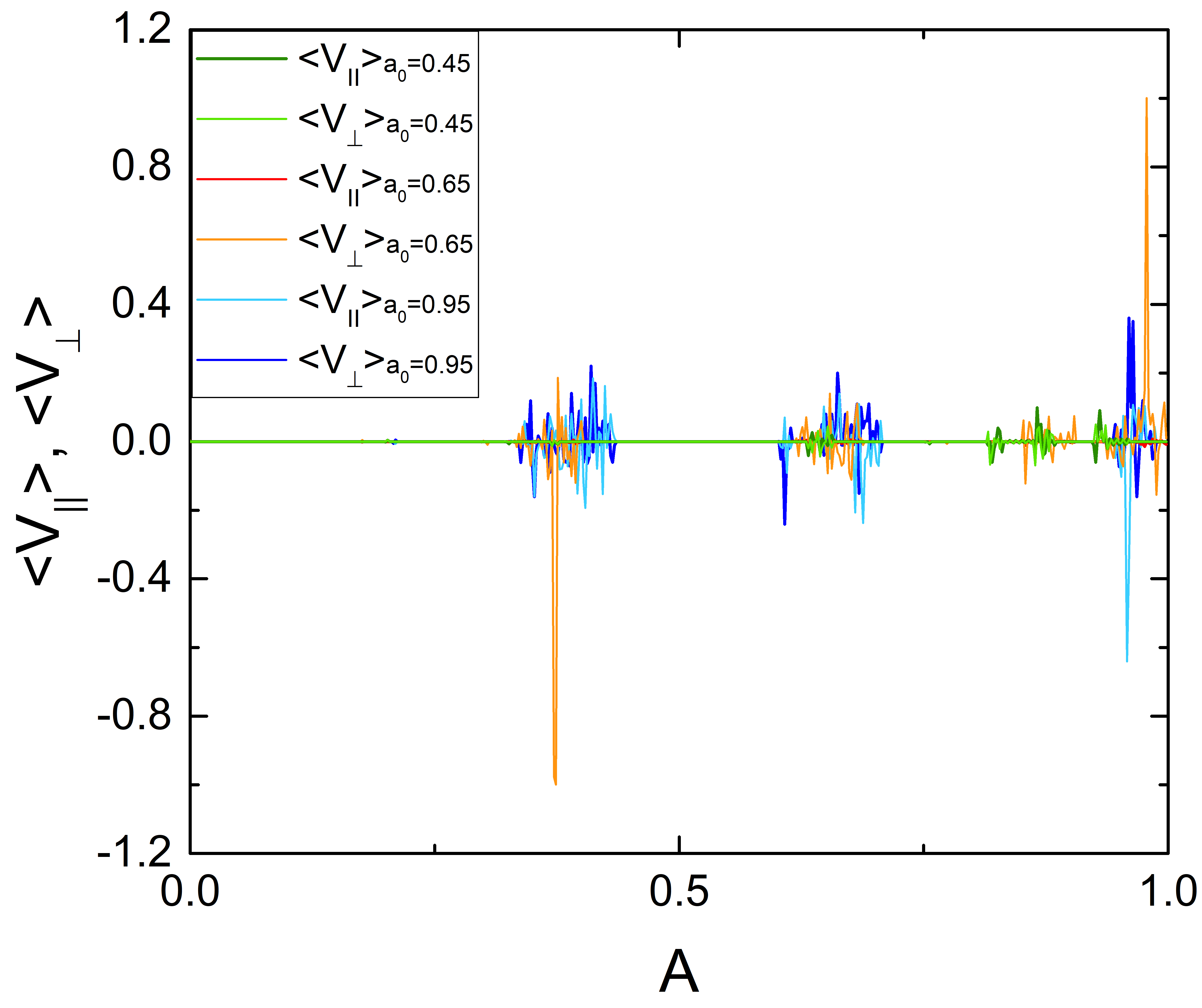
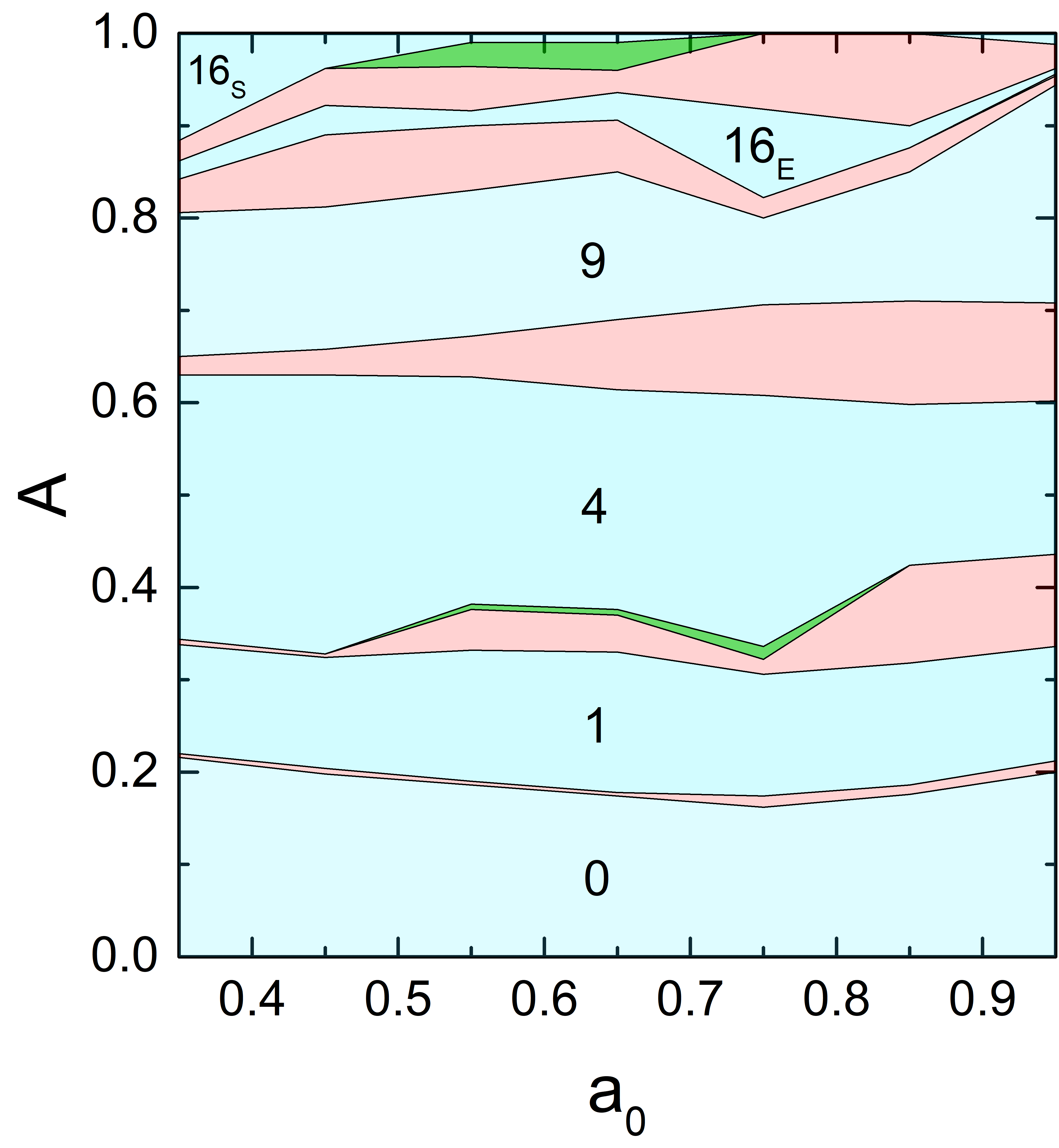
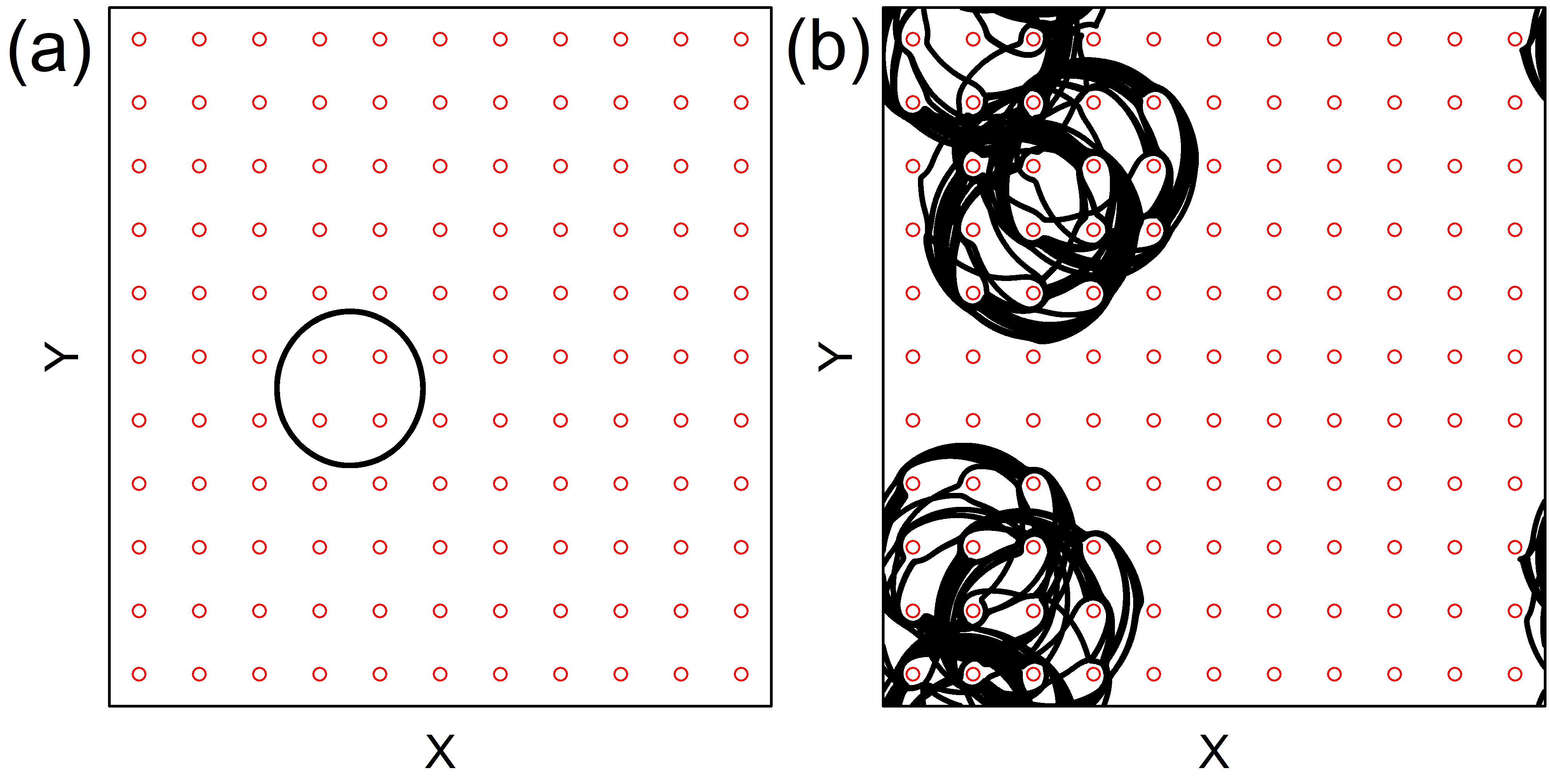
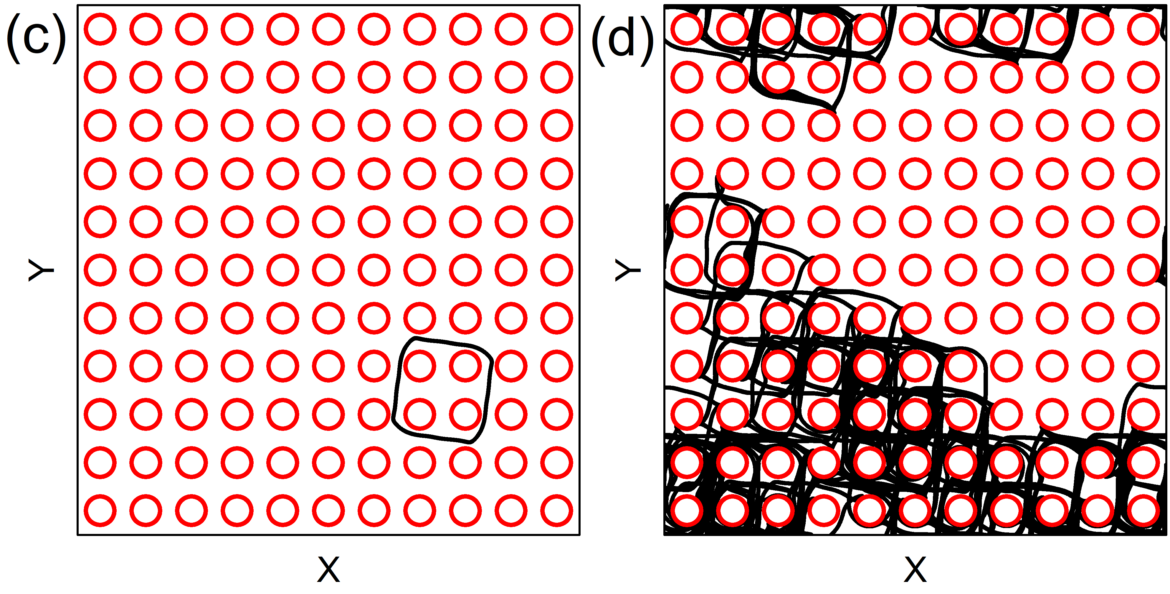
We next consider the obstacle size dependence in samples with circular ac drives for . In Fig. 21 we plot and versus for a system with at , and . For small , most of the orbits are localized. By conducting a series of simulations, we construct a dynamic phase diagram as a function of versus as shown in Fig. 22, where the locations of the localized, delocalized or chaotic, and translating phases are indicated. The localized orbits are labeled according to whether the orbit encircles 0, 1, 4, 9, or 16 obstacles. The localized orbits can also have different shapes. In Fig. 23(a) we illustrate the circular orbit at and . In contrast, the orbit in Fig. 23(c) at with is square. In general, as the obstacle radius increases, the localized orbits become more square in shape due to the symmetry of the obstacle lattice. In Fig. 23(b) we show a delocalized orbit at and , where the skyrmion collides with various obstacles and undergoes long time diffusion. A delocalized orbit at and appears in Fig. 23(d). For larger obstacles, the chaotic phases develop a stronger diffusive behavior since there is an increased probability that the skyrmion will randomly scatter off of the obstacles. The phase diagram in Fig. 22 also demonstrates that for larger , the localized orbits become elliptical, such as in the 16E state which encircles 16 obstacles, while at smaller the orbits are more circular, as in the 16S phase. For larger , there are a reduced number of delocalized or translating orbits.
V Changing ac frequency
.
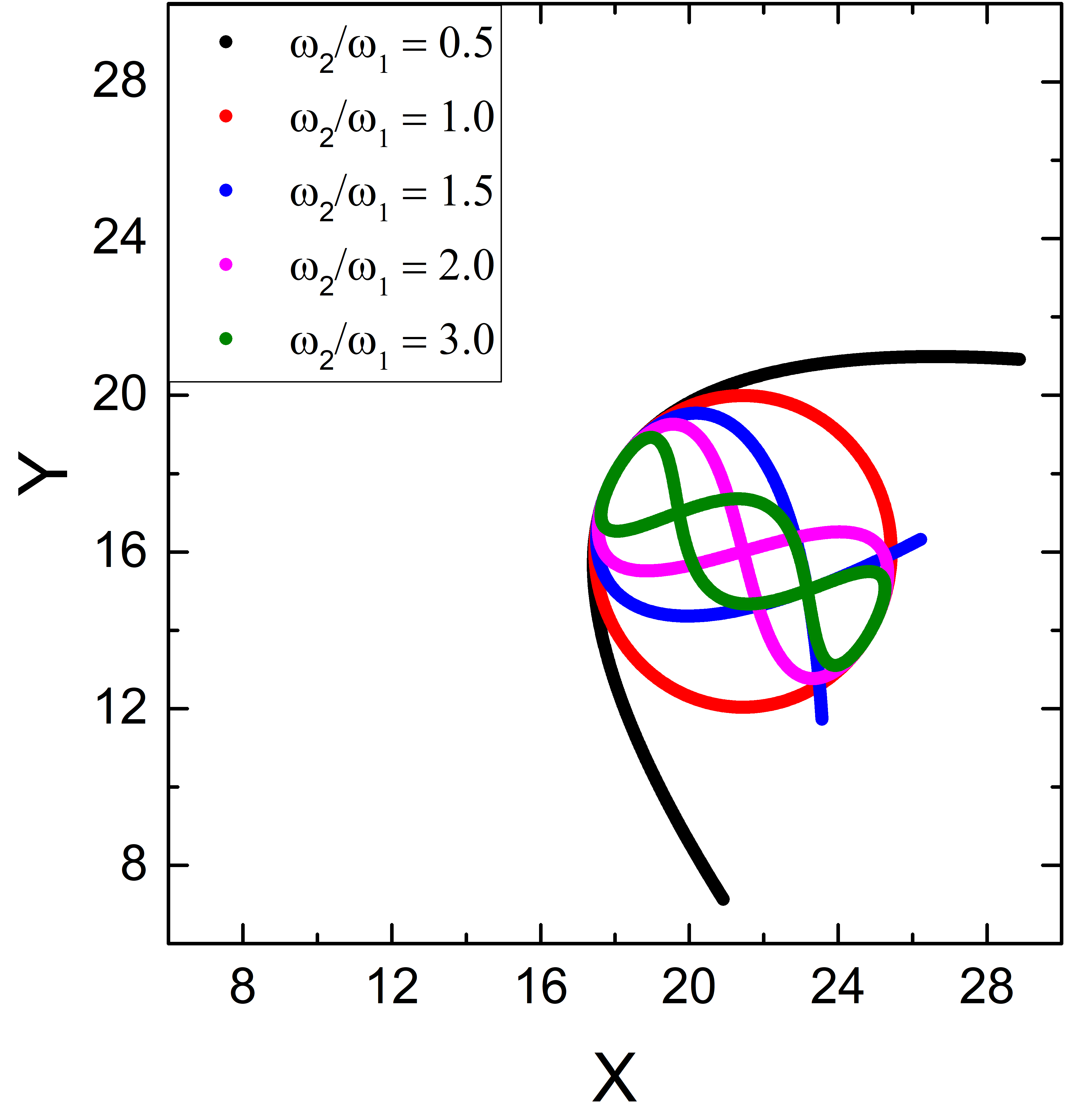
We next consider circular driving with but with two different frequencies, . In this case we find much more extensive regions of ratcheting or directed motion due to the additional asymmetry in the skyrmion orbits. In Fig. 24 we illustrate the skyrmion orbits in the absence of a substrate for a system with and at , , , , and . For , the orbit is circular; however, for the other ratios, the orbits are asymmetric.
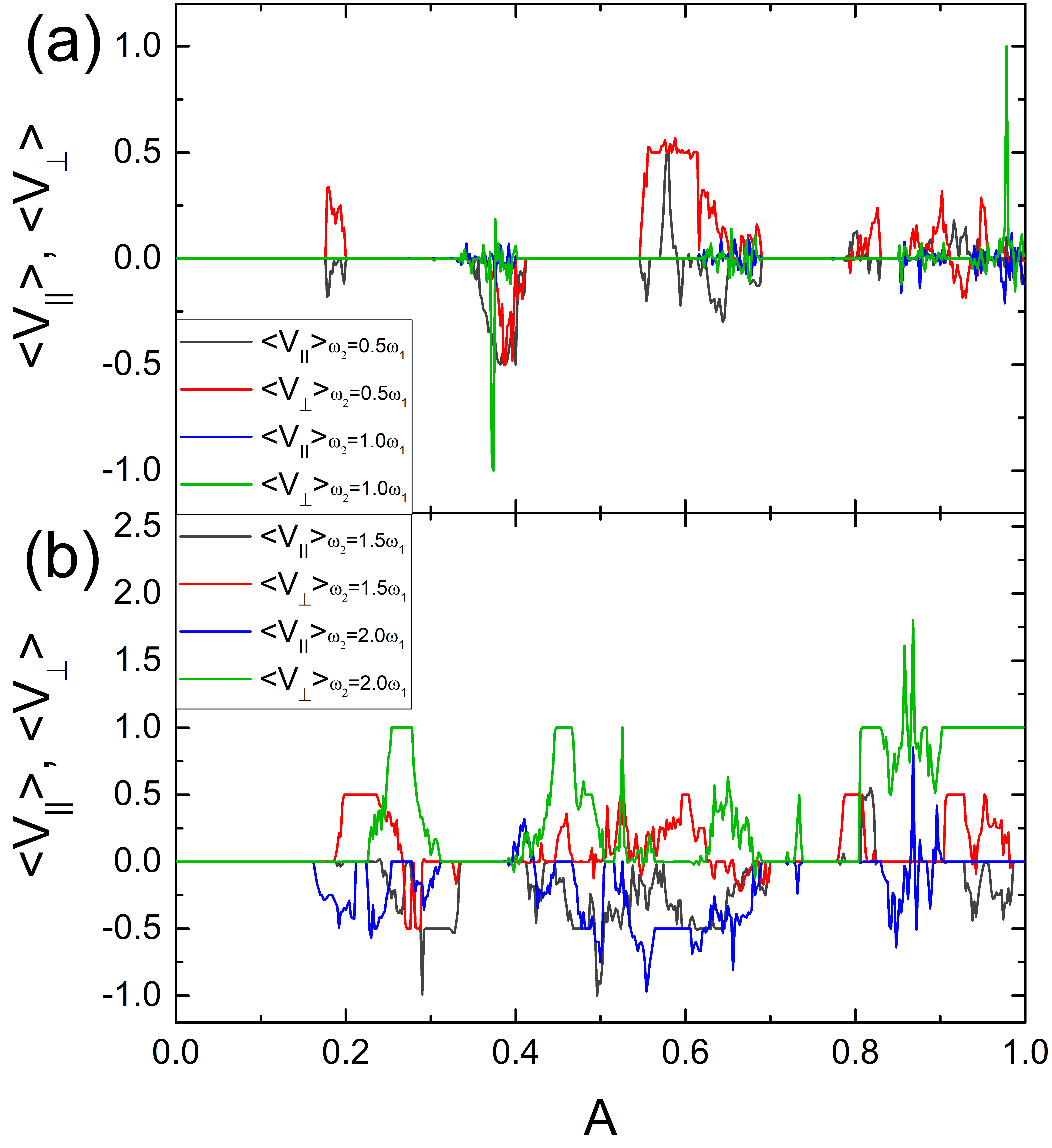
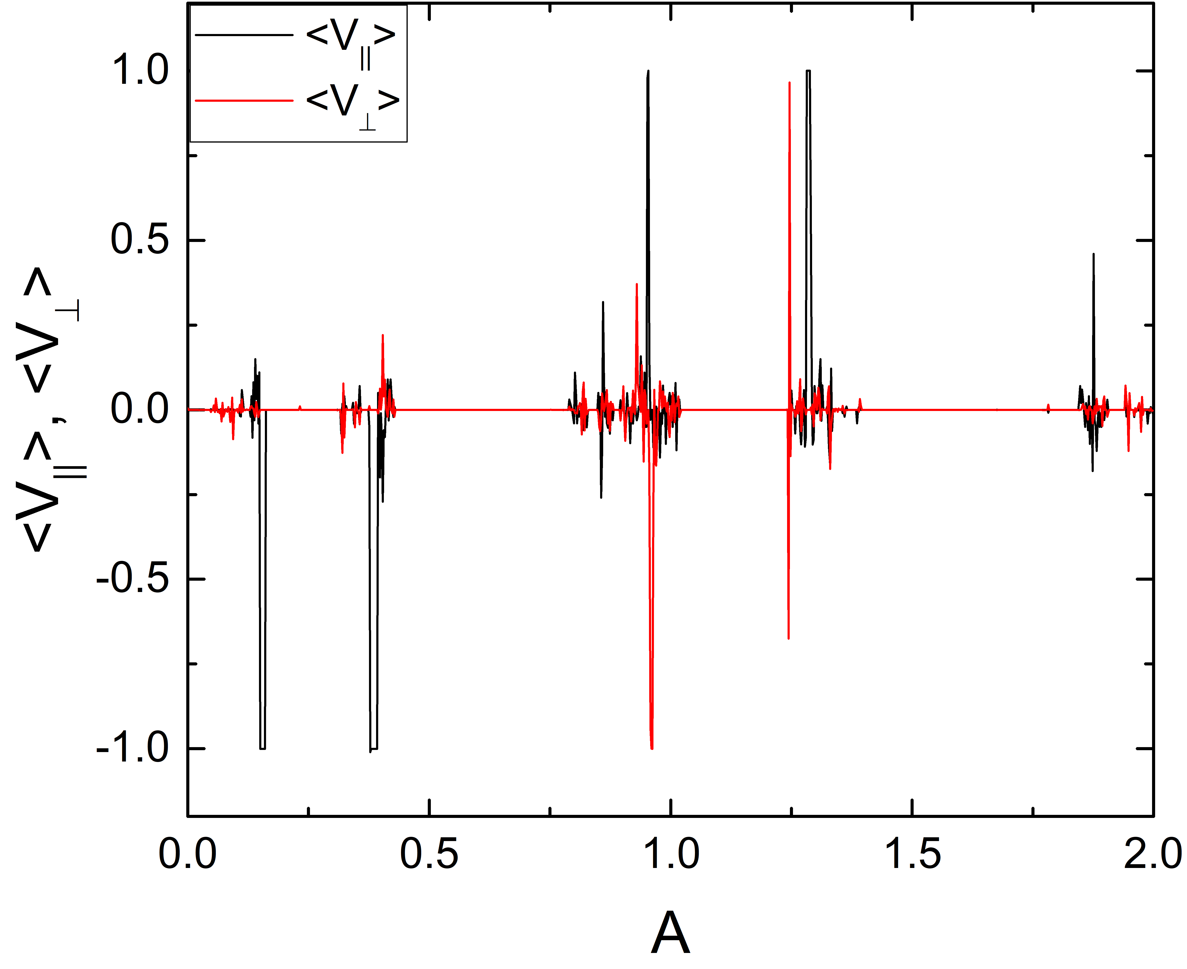
In Fig. 25(a) we plot and versus for a system with circular ac driving at , , and for and . When , there are large regions of translating orbits along with multiple reversals in the direction of translation. Figure 25(b) shows the same quantities for samples with and . When , there are several regimes in which or , indicating that the skyrmion translates by one lattice constant every two ac drive cycles, while for , there are regions where or , indicating that the skyrmion is translating by one lattice constant per ac drive cycle. Near , there is a small interval over which the skyrmion translates two lattice constants per ac drive cycle.
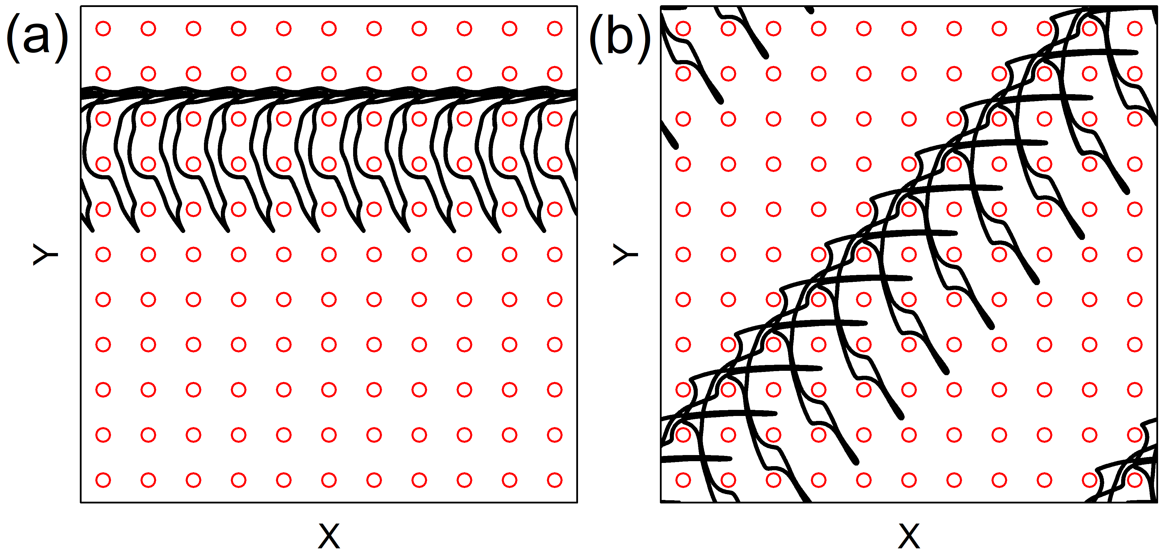
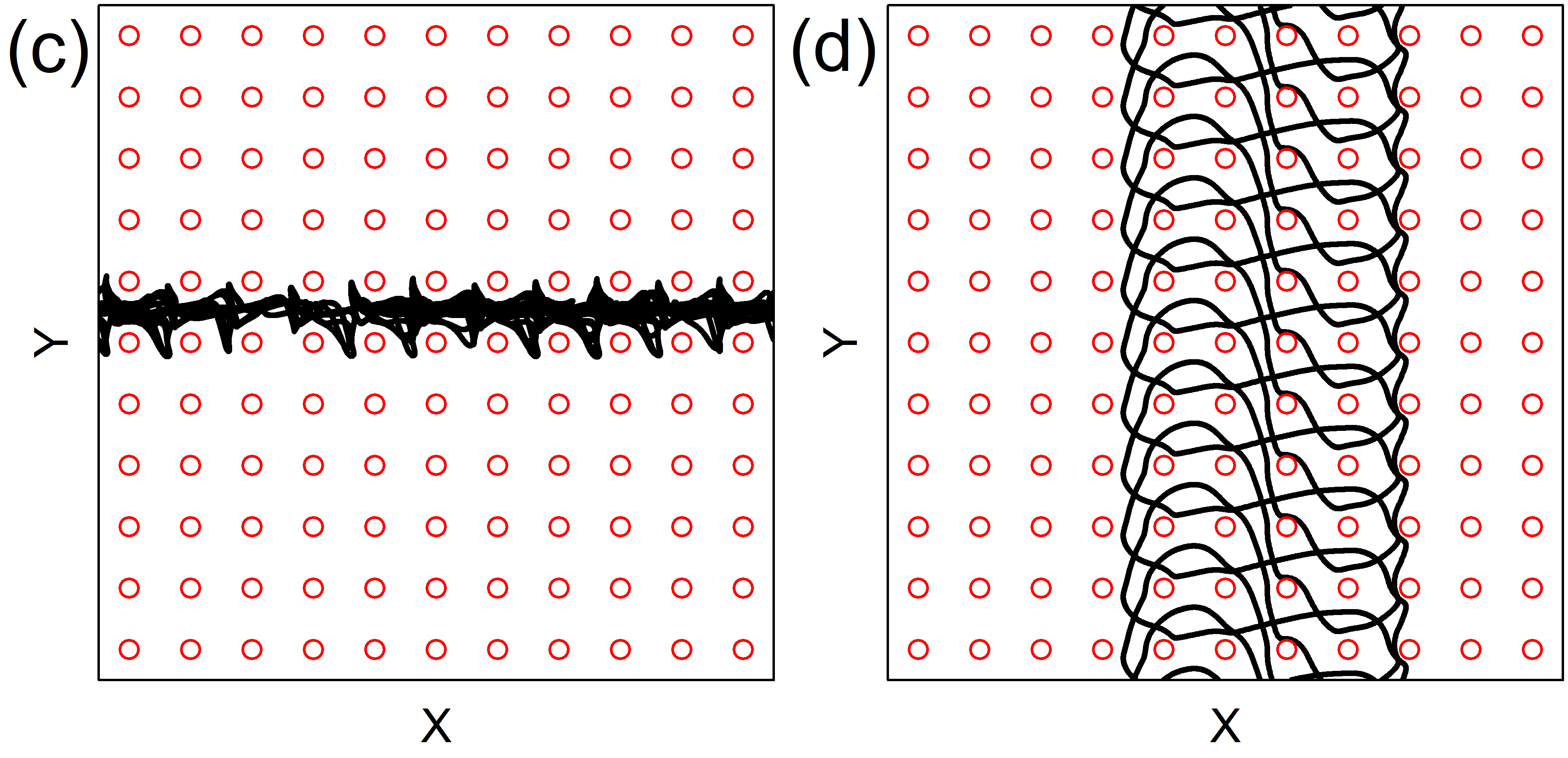
In Fig. 26(a) we illustrate the skyrmion trajectory for the system in Fig. 25(a) at and , where the skyrmion is translating in the positive -direction. At the same ratio but at , Fig. 26(b) shows that the skyrmion translates along . Figure 26(c) indicates that at and , the orbit translates in the -direction but is also disordered. In Fig. 26(d), at the same ratio but with , the skyrmion translates in the positive -direction.
In Fig. 27 we plot and versus for a system with and at . We find five translating orbit phases along with one localized phase and several localized regions. In Fig. 28(a) we illustrate the skyrmion trajectory in the first translating orbit near , where the skyrmion moves one lattice constant in the negative -direction during each ac drive cycle. Figure 28(b) shows an orbit translating in the positive direction near . In both cases, the orbit is highly complex, and the skyrmion executes three loops before translating.
VI Discussion
Our results could be tested experimentally in a system containing a periodic array of antidots with one or two applied ac drives. The different orbits could be measured using direct imaging or through electrical detection. Another method for observing the orbits is to analyze the noise fluctuations, since the localized states or ordered translating orbits should produce low noise along with a narrow band signal at a specific frequency. In contrast, the delocalized phases would exhibit broadband noise signals or multiple frequencies due to the jumping of the skyrmion between different orbit shapes. It would also be interesting to consider a finite number of skyrmions instead of an individual skyrmion. At low densities where the skyrmions do not interact, we expect that the results would be similar to what we describe above; however, for multiple interacting skyrmions, there could be an enhancement of the disordered regime or even new types of ordered phases.
In our model, the skyrmions are treated as rigid particles; however, actual skyrmions can exhibit internal modes or shape distortions which could induce additional phases. This also suggests that another method for driving skyrmions in circular orbits would be to use oscillating fields, since continuum studies have shown that this technique can generate skyrmion motion even without a substrate Chen et al. (2019). In a sample where a dc drive is superimposed on an ac drive, various types of phase locking phenomena should appear in the velocity force curves as has been studied in previous work Vizarim et al. (2020c).
Our model neglects thermal effects, but we expect such effects would become important near the transition between two different localized orbits, and could induce a creep motion for certain translating orbits. Our results also suggest that by controlling the obstacle geometry and the ac driving, it should be possible to cause the skyrmion to translate at a designated skyrmion Hall angle over a specific number of lattice constants per ac drive cycle. The behavior should also depend on the type of skyrmion considered. For antiferromagnetic skyrmions Barker and Tretiakov (2016); Legrand et al. (2020) and liquid crystal skyrmions Duzgun et al. (2020), where the Hall angle is absent, the dynamics would be similar to those found in the vortex pinball systems. In other skyrmion systems where internal modes are important, there could be complex trochoidal motion of the skyrmions Ritzmann et al. (2018). For antiskyrmions Nayak et al. (2017), additional dynamical phases could appear since the closed orbits could be more complex.
VII Summary
We have examined skyrmions interacting with a square array of repulsive obstacles or antidots under linear or circular ac driving. For linear ac driving, an overdamped particle follows a 1D orbit that does not translate; however, due to the combination of the Magnus force and interactions with the obstacles, skyrmions can execute a 2D orbit. As the ac drive amplitude increases, the skyrmion displays a series of localized orbits in which it moves between several different obstacle plaquettes or encircles one or more obstacles. In between the localized orbits, we find that there can be chaotic or disordered orbits. The transitions between the localized and delocalized orbits resemble what is found in electron pinball systems. In some cases, a linear ac drive can produce a translating or skipping skyrmion orbit. This ratchet effect is similar to what is found for colloids undergoing complex closed orbits on a periodic substrate, where the combination of the drive and the orbit asymmetry produces enough symmetry breaking to allow directed transport to emerge. In the skyrmion case, much simpler ac driving can be used to achieve the same effect. In systems with a circular ac drive, the skyrmion follows a circular orbit in the absence of a substrate, but when a substrate is present we find localized stable phases, where the skyrmion encircles an integer number of obstacles, as well as delocalized or chaotic orbits and translating orbits. The translating orbits produce motion along or or at a angle, since these are the major symmetry directions of the square obstacle lattice. The distance moved by the skyrmion in the translating orbits ranges from 1, 1/2, 1/3, 1/4, or 1/5 of a lattice constant per ac drive cycle. There are also chaotic phases that show gradual translation. As the Magnus force increases, additional translating phases appear; however, for the largest Magnus forces, disordered phases begin to dominate the behavior. We also also examine the different phases as a function of the obstacle size. The extent of the translating orbits can be enhanced by varying the amplitude or frequency of the circular ac drive in the and direction to create asymmetric orbits. Our results show that skyrmions interacting with periodic obstacle arrays under ac driving provide another example of pinball dynamics where the Magnus force induces additional features such as translating orbits. These results also suggest new ways to control skyrmion motion for device applications by using strictly ac driving.
Acknowledgements.
This work was supported by the US Department of Energy through the Los Alamos National Laboratory. Los Alamos National Laboratory is operated by Triad National Security, LLC, for the National Nuclear Security Administration of the U. S. Department of Energy (Contract No. 892333218NCA000001). N.P.V. acknowledges funding from Fundação de Amparo á Pesquisa do Estado de São Paulo - FAPESP (Grant 2018/13198-7).References
- Weiss et al. (1991) D. Weiss, M. L. Roukes, A. Menschig, P. Grambow, K. von Klitzing, and G. Weimann, “Electron pinball and commensurate orbits in a periodic array of scatterers,” Phys. Rev. Lett. 66, 2790–2793 (1991).
- Fleischmann et al. (1992) R. Fleischmann, T. Geisel, and R. Ketzmerick, “Magnetoresistance due to chaos and nonlinear resonances in lateral surface superlattices,” Phys. Rev. Lett. 68, 1367–1370 (1992).
- Ishizaka and Ando (1997) S. Ishizaka and T. Ando, “Detailed analysis of the commensurability peak in antidot arrays with various periods,” Phys. Rev. B 55, 16331–16338 (1997).
- Meckler et al. (2005) S. Meckler, T. Heinzel, A. Cavanna, G. Faini, U. Gennser, and D. Mailly, “Commensurability effects in hexagonal antidot lattices with large antidot diameters,” Phys. Rev. B 72, 035319 (2005).
- Weiss et al. (1993) D. Weiss, K. Richter, A. Menschig, R. Bergmann, H. Schweizer, K. von Klitzing, and G. Weimann, “Quantized periodic orbits in large antidot arrays,” Phys. Rev. Lett. 70, 4118–4121 (1993).
- Kato et al. (2012) Y. Kato, A. Endo, S. Katsumoto, and Y. Iye, “Geometric resonances in the magnetoresistance of hexagonal lateral superlattices,” Phys. Rev. B 86, 235315 (2012).
- Onderka et al. (2000) R. Onderka, M. Suhrke, and U. Rössler, “Anisotropic magnetotransport in a rectangular antidot superlattice: Classical and semiclassical aspects,” Phys. Rev. B 62, 10918–10922 (2000).
- Geisler et al. (2005) M. C. Geisler, S. Chowdhury, J. H. Smet, L. Höppel, V. Umansky, R. R. Gerhardts, and K. von Klitzing, “Experimental evidence for predicted magnetotransport anomalies in rectangular superlattices,” Phys. Rev. B 72, 045320 (2005).
- Klinkhammer et al. (2008) S. Klinkhammer, Hengyi Xu, T. Heinzel, U. Gennser, G. Faini, C. Ulysse, and A. Cavanna, “Magnetoresistance of antidot lattices with grain boundaries,” Phys. Rev. B 77, 235311 (2008).
- Siboni et al. (2018) N. H. Siboni, J. Schluck, K. Pierz, H. W. Schumacher, D. Kazazis, J. Horbach, and T. Heinzel, “Nonmonotonic classical magnetoconductivity of a two-dimensional electron gas in a disordered array of obstacles,” Phys. Rev. Lett. 120, 056601 (2018).
- Sandner et al. (2015) A. Sandner, T. Preis, C. Schell, P. Giudici, K. Watanabe, T. Taniguchi, D. Weiss, and J. Eroms, “Ballistic transport in graphene antidot lattices,” Nano Lett. 15, 8402–8406 (2015).
- Power et al. (2017) S. R. Power, M. R. Thomsen, A.-P. Jauho, and T. G. Pedersen, “Electron trajectories and magnetotransport in nanopatterned graphene under commensurability conditions,” Phys. Rev. B 96, 075425 (2017).
- Maier et al. (2017) H. Maier, J. Ziegler, R. Fischer, D. Kozlov, Z. D. Kvon, N. Mikhailov, S. A. Dvoretsky, and D. Weiss, “Ballistic geometric resistance resonances in a single surface of a topological insulator,” Nature Commun. 8, 2023 (2017).
- Deng et al. (2016) H. Deng, Y. Liu, I. Jo, L. N. Pfeiffer, K. W. West, K. W. Baldwin, and M. Shayegan, “Commensurability oscillations of composite fermions induced by the periodic potential of a Wigner crystal,” Phys. Rev. Lett. 117, 096601 (2016).
- Jo et al. (2018) Insun Jo, Hao Deng, Yang Liu, L. N. Pfeiffer, K. W. West, K. W. Baldwin, and M. Shayegan, “Cyclotron orbits of composite fermions in the fractional quantum Hall regime,” Phys. Rev. Lett. 120, 016802 (2018).
- Reichhardt and Olson (2002) C. Reichhardt and C. J. Olson, “Vortex pinball under crossed ac drives in superconductors with periodic pinning arrays,” Phys. Rev. B 65, 100501 (2002).
- Tierno et al. (2007) P. Tierno, T. H. Johansen, and T. M. Fischer, “Localized and delocalized motion of colloidal particles on a magnetic bubble lattice,” Phys. Rev. Lett. 99, 038303 (2007).
- Loehr et al. (2016) J. Loehr, M. Loenne, A. Ernst, D. de las Heras, and T. M. Fischer, “Topological protection of multiparticle dissipative transport,” Nature Commun. 7, 11745 (2016).
- Reichhardt and Olson Reichhardt (2003) C. Reichhardt and C. J. Olson Reichhardt, “Absolute transverse mobility and ratchet effect on periodic two-dimensional symmetric substrates,” Phys. Rev. E 68, 046102 (2003).
- Speer et al. (2009) D. Speer, R. Eichhorn, and P. Reimann, “Directing Brownian motion on a periodic surface,” Phys. Rev. Lett. 102, 124101 (2009).
- Platonov et al. (2015) S. Platonov, B. Kästner, H. W. Schumacher, S. Kohler, and S. Ludwig, “Lissajous rocking ratchet: Realization in a semiconductor quantum dot,” Phys. Rev. Lett. 115, 106801 (2015).
- Reimann (2002) P Reimann, “Brownian motors: noisy transport far from equilibrium,” Phys. Rep. 361, 57–265 (2002).
- Loehr et al. (2018) J. Loehr, D. de las Heras, A. Jarosz, M. Urbaniak, F. Stobiecki, A. Tomita, R. Huhnstock, I. Koch, A. Ehresmann, D. Holzinger, and T. M. Fischer, “Colloidal topological insulators,” Commun. Phys. 1, 4 (2018).
- Massana-Cid et al. (2019) H. Massana-Cid, A. Ernst, D. de las Heras, A. Jarosz, M. Urbaniak, F. Stobiecki, A. Tomita, R. Huhnstock, I. Koch, A. Ehresmann, D. Holzinger, and T. M. Fischer, “Edge transport at the boundary between topologically equivalent lattices,” Soft Matter 15, 1539–1550 (2019).
- Yazdi et al. (2020) S. Yazdi, J. L. Aragones, J. Coulter, and A. Alexander-Katz, “Metamaterials for active colloid transport,” arXiv:2002.06477 (2020).
- Mühlbauer et al. (2009) S. Mühlbauer, B. Binz, F. Jonietz, C. Pfleiderer, A. Rosch, A. Neubauer, R. Georgii, and P. Böni, “Skyrmion lattice in a chiral magnet,” Science 323, 915–919 (2009).
- Everschor-Sitte et al. (2018) K. Everschor-Sitte, J. Masell, R. M. Reeve, and M. Klaüi, “Perspective: Magnetic skyrmions - Overview of recent progress in an active research field,” J. Appl. Phys. 124, 240901 (2018).
- Yu et al. (2010) X. Z. Yu, Y. Onose, N. Kanazawa, J. H. Park, J. H. Han, Y. Matsui, N. Nagaosa, and Y. Tokura, “Real-space observation of a two-dimensional skyrmion crystal,” Nature (London) 465, 901–904 (2010).
- Nagaosa and Tokura (2013) N. Nagaosa and Y. Tokura, “Topological properties and dynamics of magnetic skyrmions,” Nature Nanotechnol. 8, 899–911 (2013).
- Woo et al. (2016) S. Woo, K. Litzius, B. Krüger, M.-Y. Im, L. Caretta, K. Richter, M. Mann, A. Krone, R. M. Reeve, M. Weigand, P. Agrawal, I. Lemesh, M.-A. Mawass, P. Fischer, M. Kläui, and G. S. D. Beach, “Observation of room-temperature magnetic skyrmions and their current-driven dynamics in ultrathin metallic ferromagnets,” Nature Mater. 15, 501 (2016).
- Soumyanarayanan et al. (2017) A. Soumyanarayanan, M. Raju, A. L. G. Oyarce, A. K. C. Tan, M.-Y. Im, A. P. Petrovic, P. Ho, K. H. Khoo, M. Tran, C. K. Gan, F. Ernult, and C. Panagopoulos, “Tunable room-temperature magnetic skyrmions in Ir/Fe/Co/Pt multilayers,” Nature Mater. 16, 898 (2017).
- Schulz et al. (2012) T. Schulz, R. Ritz, A. Bauer, M. Halder, M. Wagner, C. Franz, C. Pfleiderer, K. Everschor, M. Garst, and A. Rosch, “Emergent electrodynamics of skyrmions in a chiral magnet,” Nature Phys. 8, 301–304 (2012).
- Yu et al. (2012) X. Z. Yu, N. Kanazawa, W. Z. Zhang, T. Nagai, T. Hara, K. Kimoto, Y. Matsui, Y. Onose, and Y. Tokura, “Skyrmion flow near room temperature in an ultralow current density,” Nature Commun. 3, 988 (2012).
- Iwasaki et al. (2013) J. Iwasaki, M. Mochizuki, and N. Nagaosa, “Universal current-velocity relation of skyrmion motion in chiral magnets,” Nature Commun. 4, 1463 (2013).
- Lin et al. (2013a) S.-Z. Lin, C. Reichhardt, C. D. Batista, and A. Saxena, “Driven skyrmions and dynamical transitions in chiral magnets,” Phys. Rev. Lett. 110, 207202 (2013a).
- Liang et al. (2015) D. Liang, J. P. DeGrave, M. J. Stolt, Y. Tokura, and S. Jin, “Current-driven dynamics of skyrmions stabilized in MnSi nanowires revealed by topological Hall effect,” Nature Commun. 6, 8217 (2015).
- Montoya et al. (2018) S. A. Montoya, R. Tolley, I. Gilbert, S.-G. Je, M.-Y. Im, and E. E. Fullerton, “Spin-orbit torque induced dipole skyrmion motion at room temperature,” Phys. Rev. B 98, 104432 (2018).
- Díaz et al. (2017) S. A. Díaz, C. J. O. Reichhardt, D. P. Arovas, A. Saxena, and C. Reichhardt, “Fluctuations and noise signatures of driven magnetic skyrmions,” Phys. Rev. B 96, 085106 (2017).
- Sato et al. (2019) T. Sato, W. Koshibae, A. Kikkawa, T. Yokouchi, H. Oike, Y. Taguchi, N. Nagaosa, Y. Tokura, and F. Kagawa, “Slow steady flow of a skyrmion lattice in a confined geometry probed by narrow-band resistance noise,” Phys. Rev. B 100, 094410 (2019).
- Tomasello et al. (2014) R. Tomasello, E. Martinez, R. Zivieri, L. Torres, M. Carpentieri, and G. Finocchio, “A strategy for the design of skyrmion racetrack memories,” Sci. Rep. 4, 6784 (2014).
- Fert et al. (2017) A. Fert, N. Reyren, and V. Cros, “Magnetic skyrmions: advances in physics and potential applications,” Nature Rev. Mater. 2, 17031 (2017).
- Prychynenko et al. (2018) D. Prychynenko, M. Sitte, K. Litzius, B. Krüger, G. Bourianoff, M. Kläui, J. Sinova, and K. Everschor-Sitte, “Magnetic skyrmion as a nonlinear resistive element: A potential building block for reservoir computing,” Phys. Rev. Applied 9, 014034 (2018).
- Song et al. (2020) K. M. Song, J.-S. Jeong, B. Pan, X. Zhang, J. Xia, S. Cha, T.-E. Park, K. Kim, S. Finizio, J. Raabe, J. Chang, J. Zhou, W. Zhao, W. Kang, H. Ju, and S. Woo, “Skyrmion-based artificial synapses for neuromorphic computing,” Nat. Electron. 3, 148–155 (2020).
- Reichhardt et al. (2015a) C. Reichhardt, D. Ray, and C. J. Olson Reichhardt, “Magnus-induced ratchet effects for skyrmions interacting with asymmetric substrates,” New J. Phys. 17, 073034 (2015a).
- Reichhardt and Reichhardt (2015) C. Reichhardt and C. J. Olson Reichhardt, “Shapiro steps for skyrmion motion on a washboard potential with longitudinal and transverse ac drives,” Phys. Rev. B 92, 224432 (2015).
- Reichhardt and Reichhardt (2016) C. Reichhardt and C. J. Olson Reichhardt, “Magnus-induced dynamics of driven skyrmions on a quasi-one-dimensional periodic substrate,” Phys. Rev. B 94, 094413 (2016).
- Navau et al. (2016) C. Navau, N. Del-Valle, and A. Sanchez, “Analytical trajectories of skyrmions in confined geometries: Skyrmionic racetracks and nano-oscillators,” Phys. Rev. B 94, 184104 (2016).
- Ma et al. (2016) F. Ma, C. Reichhardt, W. Gan, C. J. O. Reichhardt, and W. S. Lew, “Emergent geometric frustration of artificial magnetic skyrmion crystals,” Phys. Rev. B 94, 144405 (2016).
- Ma et al. (2017) X. Ma, C. J. Olson Reichhardt, and C. Reichhardt, “Reversible vector ratchets for skyrmion systems,” Phys. Rev. B 95, 104401 (2017).
- Stosic et al. (2017) D. Stosic, T. B. Ludermir, and M. V. Milošević, “Pinning of magnetic skyrmions in a monolayer Co film on Pt(111): Theoretical characterization and exemplified utilization,” Phys. Rev. B 96, 214403 (2017).
- Fernandes et al. (2018) I. L. Fernandes, J. Bouaziz, S. Blügel, and S. Lounis, “Universality of defect-skyrmion interaction profiles,” Nature Commun. 9, 4395 (2018).
- Toscano et al. (2019) D. Toscano, S. A. Leonel, P. Z. Coura, and F. Sato, “Building traps for skyrmions by the incorporation of magnetic defects into nanomagnets: Pinning and scattering traps by magnetic properties engineering,” J. Mag. Mag. Mater. 480, 171–185 (2019).
- Reichhardt et al. (2015b) C. Reichhardt, D. Ray, and C. J. Olson Reichhardt, “Quantized transport for a skyrmion moving on a two-dimensional periodic substrate,” Phys. Rev. B 91, 104426 (2015b).
- Saha et al. (2019) S. Saha, M. Zelent, S. Finizio, M. Mruczkiewicz, S. Tacchi, A. K. Suszka, S. Wintz, N. S. Bingham, J. Raabe, M. Krawczyk, and L. J. Heyderman, “Formation of néel-type skyrmions in an antidot lattice with perpendicular magnetic anisotropy,” Phys. Rev. B 100, 144435 (2019).
- Feilhauer et al. (2019) J. Feilhauer, S. Saha, J. Tobik, M. Zelent, L. J. Heyderman, and M. Mruczkiewicz, “Controlled motion of skyrmions in a magnetic antidot lattice,” arXiv:1910.07388 (2019).
- Vizarim et al. (2020a) N. P. Vizarim, C. Reichhardt, C. J. O. Reichhardt, and P. Venegas, “Skyrmion dynamics and topological sorting on periodic obstacle arrays,” New J. Phys. (in press) (2020a).
- Everschor-Sitte and Sitte (2014) K. Everschor-Sitte and M. Sitte, “Real-space Berry phases: Skyrmion soccer (invited),” J. Appl. Phys. 115, 172602 (2014).
- Reichhardt et al. (2015c) C. Reichhardt, D. Ray, and C. J. Olson Reichhardt, “Collective transport properties of driven skyrmions with random disorder,” Phys. Rev. Lett. 114, 217202 (2015c).
- Jiang et al. (2017) W. Jiang, X. Zhang, G. Yu, W. Zhang, X. Wang, M. B. Jungfleisch, J. E. Pearson, X. Cheng, O. Heinonen, K. L. Wang, Y. Zhou, A. Hoffmann, and S. G. E. te Velthuis, “Direct observation of the skyrmion Hall effect,” Nature Phys. 13, 162–169 (2017).
- Litzius et al. (2017) K. Litzius, I. Lemesh, B. Krüger, P. Bassirian, L. Caretta, K. Richter, F. Büttner, K. Sato, O. A. Tretiakov, J. Förster, R. M. Reeve, M. Weigand, L. Bykova, H. Stoll, G. Schütz, G. S. D. Beach, and M. Kläui, “Skyrmion Hall effect revealed by direct time-resolved X-ray microscopy,” Nature Phys. 13, 170–175 (2017).
- Woo et al. (2018) S. Woo, K. M. Song, X. Zhang, Y. Zhou, M. Ezawa, X. Liu, S. Finizio, J. Raabe, N. J. Lee, S. Kim, S.-Y. Park, Y. Kim, J.-Y. Kim, D. Lee, O. Lee, J. W. Choi, B.-C. Min, H. C. Koo, and J. Chang, “Current-driven dynamics and inhibition of the skyrmion Hall effect of ferrimagnetic skyrmions in GdFeCo films,” Nature Commun. 9, 959 (2018).
- Juge et al. (2019) R. Juge, S.-G. Je, D. de Souza Chaves, L. D. Buda-Prejbeanu, J. Peña Garcia, J. Nath, I. M. Miron, K. G. Rana, L. Aballe, M. Foerster, F. Genuzio, T. O. Menteş, A. Locatelli, F. Maccherozzi, S. S. Dhesi, M. Belmeguenai, Y. Roussigné, S. Auffret, S. Pizzini, G. Gaudin, J. Vogel, and O. Boulle, “Current-driven skyrmion dynamics and drive-dependent skyrmion Hall effect in an ultrathin film,” Phys. Rev. Applied 12, 044007 (2019).
- Zeissler et al. (2020) K. Zeissler, S. Finizio, C. Barton, A. J. Huxtable, J. Massey, J. Raabe, A. V. Sadovnikov, S. A. Nikitov, R. Brearton, T. Hesjedal, G. van der Laan, M. C. Rosamond, E. H. Linfield, G. Burnell, and C. H. Marrows, “Diameter-independent skyrmion Hall angle observed in chiral magnetic multilayers,” Nature Commun. 11, 428 (2020).
- Müller and Rosch (2015) J. Müller and A. Rosch, “Capturing of a magnetic skyrmion with a hole,” Phys. Rev. B 91, 054410 (2015).
- Kim and Yoo (2017) J.-V. Kim and M.-W. Yoo, “Current-driven skyrmion dynamics in disordered films,” Appl. Phys. Lett. 110, 132404 (2017).
- Legrand et al. (2017) W. Legrand, D. Maccariello, N. Reyren, K. Garcia, C. Moutafis, C. Moreau-Luchaire, S. Coffin, K. Bouzehouane, V. Cros, and A. Fert, “Room-temperature current-induced generation and motion of sub-100 nm skyrmions,” Nano Lett. 17, 2703–2712 (2017).
- Reichhardt and Reichhardt (2019a) C. Reichhardt and C. J. O. Reichhardt, “Thermal creep and the skyrmion Hall angle in driven skyrmion crystals,” J. Phys.: Condens. Matter 31, 07LT01 (2019a).
- Reichhardt and Reichhardt (2019b) C. Reichhardt and C. J. O. Reichhardt, “Nonlinear transport, dynamic ordering, and clustering for driven skyrmions on random pinning,” Phys. Rev. B 99, 104418 (2019b).
- Reichhardt and Reichhardt (2020) C. Reichhardt and C. J. O. Reichhardt, “Plastic flow and the skyrmion hall effect,” Nature Commun. 11, 738 (2020).
- Litzius et al. (2020) K. Litzius, J. Leliaert, P. Bassirian, D. Rodrigues, S. Kromin, I. Lemesh, J. Zazvorka, K.-J. Lee, J. Mulkers, N. Kerber, D. Heinze, N. Keil, R. M. Reeve, M. Weigand, B. Van Waeyenberge, G. Schütz, K. Everschor-Sitte, G. S. D. Beach, and M. Klaüi, “The role of temperature and drive current in skyrmion dynamics,” Nature Electron. 3, 30–36 (2020).
- Reichhardt and Nori (1999) C. Reichhardt and F. Nori, “Phase locking, devil’s staircases, Farey trees, and Arnold tongues in driven vortex lattices with periodic pinning,” Phys. Rev. Lett. 82, 414–417 (1999).
- Korda et al. (2002) P. T. Korda, M. B. Taylor, and D. G. Grier, “Kinetically locked-in colloidal transport in an array of optical tweezers,” Phys. Rev. Lett. 89, 128301 (2002).
- MacDonald et al. (2003) M. P. MacDonald, G. C. Spalding, and K. Dholakia, “Microfluidic sorting in an optical lattice,” Nature (London) 426, 421–424 (2003).
- Reichhardt and Reichhardt (2012) C. Reichhardt and C. J. Olson Reichhardt, “Structural transitions and dynamical regimes for directional locking of vortices and colloids driven over periodic substrates,” J. Phys.: Condens. Matter 24, 225702 (2012).
- Vizarim et al. (2020b) N. P. Vizarim, C. Reichhardt, P. A. Venegas, and C. J. O. Reichhardt, “Shapiro steps and nonlinear skyrmion Hall angles for dc and ac driven skyrmions on a two dimensional periodic substrate,” arXiv:2003.04395 (2020b).
- Lin et al. (2013b) S.-Z. Lin, C. Reichhardt, C. D. Batista, and A. Saxena, “Particle model for skyrmions in metallic chiral magnets: Dynamics, pinning, and creep,” Phys. Rev. B 87, 214419 (2013b).
- Brown et al. (2019) B. L. Brown, U. C. Täuber, and M. Pleimling, “Skyrmion relaxation dynamics in the presence of quenched disorder,” Phys. Rev. B 100, 024410 (2019).
- Xiong et al. (2019) L. Xiong, B. Zheng, M. H. Jin, and N. J. Zhou, “Collective transport properties of skyrmions on the depinning phase transition,” Phys. Rev. B 100, 064426 (2019).
- Chen et al. (2019) W. Chen, L. Liu, Y. Ji, and Y. Zheng, “Skyrmion ratchet effect driven by a biharmonic force,” Phys. Rev. B 99, 064431 (2019).
- Vizarim et al. (2020c) N. P. Vizarim, C. Reichhardt, P. A. Venegas, and C. J. O. Reichhardt, “Skyrmion dynamics and transverse mobility: Skyrmion Hall angle reversal on 2D periodic substrates with dc and biharmonic ac drives,” arXiv:2003.05972 (2020c).
- Barker and Tretiakov (2016) J. Barker and O. A. Tretiakov, “Static and dynamical properties of antiferromagnetic skyrmions in the presence of applied current and temperature,” Phys. Rev. Lett. 116, 147203 (2016).
- Legrand et al. (2020) W. Legrand, D. Maccariello, F. Ajejas, S. Collin, A. Vecchiola, K. Bouzehouane, N. Reyren, V. Cros, and A. Fert, “Room-temperature stabilization of antiferromagnetic skyrmions in synthetic antiferromagnets,” Nature Mater. 19, 34–42 (2020).
- Duzgun et al. (2020) A. Duzgun, C. Nisoli, C. J. O. Reichhardt, and C. Reichhardt, “Commensurate states and pattern switching via liquid crystal skyrmions trapped in a square lattice,” Soft Matter (in press) (2020).
- Ritzmann et al. (2018) U. Ritzmann, S. von Malottki, J.-V. Kim, S. Heinze, J. Sinova, and B. Dupe, “Trochoidal motion and pair generation in skyrmion and antiskyrmion dynamics under spin-orbit torques,” Nature Electron. 1, 451–457 (2018).
- Nayak et al. (2017) A. K. Nayak, V. Kumar, T. Ma, P. Werner, E. Pippel, R. Sahoo, F. Damay, U. K. Roessler, C. Felser, and S. S. P. Parkin, “Magnetic antiskyrmions above room temperature in tetragonal Heusler materials,” Nature (London) 548, 561 (2017).