Α \newunicodecharα \newunicodecharΒ \newunicodecharβ \newunicodecharΓ \newunicodecharγ \newunicodecharΔ \newunicodecharδ \newunicodecharΕ \newunicodecharε \newunicodecharϵ \newunicodecharΖ \newunicodecharζ \newunicodecharΗ \newunicodecharη \newunicodecharΘ \newunicodecharθ \newunicodecharϑ \newunicodecharΙ \newunicodecharι \newunicodecharΚ \newunicodecharκ \newunicodecharΛ \newunicodecharλ \newunicodecharΜ \newunicodecharμ \newunicodecharΝ \newunicodecharν \newunicodecharΞ \newunicodecharξ \newunicodecharΟ \newunicodecharο \newunicodecharΠ \newunicodecharπ \newunicodecharϖ \newunicodecharΡ \newunicodecharρ \newunicodecharϱ \newunicodecharΣ \newunicodecharσ \newunicodecharς \newunicodecharΤ \newunicodecharτ \newunicodecharΥ \newunicodecharυ \newunicodecharΦ \newunicodecharφ \newunicodecharϕ \newunicodecharΧ \newunicodecharχ \newunicodecharΨ \newunicodecharψ \newunicodecharΩ \newunicodecharω \newunicodecharℂ \newunicodecharℤ \newunicodecharℝ \newunicodecharℕ \newunicodecharℚ \newunicodecharℰ \newunicodecharℱ \newunicodecharℋ \newunicodecharℑ \newunicodecharℒ \newunicodecharℳ \newunicodecharℛ \newunicodecharℜ \newunicodecharℓ \newunicodechar∼ \newunicodechar≈ \newunicodechar≋ \newunicodechar≅ \newunicodechar≡ \newunicodechar≤ \newunicodechar≥ \newunicodechar≲ \newunicodechar≠ \newunicodechar≔ \newunicodechar⋆ \newunicodecharƛ \newunicodechar± \newunicodechar∓ \newunicodechar× \newunicodechar→ \newunicodechar← \newunicodechar⇒ \newunicodechar↦ \newunicodechar↝ \newunicodechar⸖ \newunicodechar⇆ \newunicodechar↔ \newunicodechar↭ \newunicodechar↣ \newunicodechar∀ \newunicodechar∃ \newunicodechar∨ \newunicodechar∧ \newunicodechar⊢ \newunicodechar⊣ \newunicodechar⊤ \newunicodechar⊥ \newunicodechar¬ \newunicodechar⊸ \newunicodechar⊗ \newunicodechar⊕ \newunicodechar¡ \newunicodechar⨂ \newunicodechar⨁ \newunicodechar∈ \newunicodechar∉ \newunicodechar⊆ \newunicodechar∪ \newunicodechar⋓ \newunicodechar∅ \newunicodechar⟨ \newunicodechar⟨ \newunicodechar⟩ \newunicodechar⟩ \newunicodechar⟦ \newunicodechar⟧ \newunicodechar₀0 \newunicodechar₁1 \newunicodechar₂2 \newunicodechar₃3 \newunicodechar₄4 \newunicodechar₅5 \newunicodechar₆6 \newunicodechar₇7 \newunicodechar₈8 \newunicodechar₉9 \newunicodecharₐa \newunicodecharₑe \newunicodecharₕh \newunicodecharᵢi \newunicodecharⱼj \newunicodecharₖk \newunicodecharₗl \newunicodecharₘm \newunicodecharₙn \newunicodecharₒo \newunicodecharₚp \newunicodecharᵣr \newunicodecharₛs \newunicodecharₜt \newunicodecharᵤu \newunicodecharₓx \newunicodechar⁰0 \newunicodechar¹1 \newunicodechar²2 \newunicodechar³3 \newunicodechar⁴4 \newunicodechar⁵5 \newunicodechar⁶6 \newunicodechar⁷7 \newunicodechar⁸8 \newunicodechar⁹9 \newunicodecharᵃa \newunicodecharᵇb \newunicodecharᶜc \newunicodecharᵈd \newunicodecharᵉe \newunicodecharᶠf \newunicodecharᵍg \newunicodecharʰh \newunicodecharⁱi \newunicodecharʲj \newunicodecharᵏk \newunicodecharᵐm \newunicodecharⁿn \newunicodecharᵒo \newunicodecharᵖp \newunicodecharˢs \newunicodecharᵗt \newunicodecharᵘu \newunicodecharʷv \newunicodecharˣx \newunicodecharʸy \newunicodecharᶻz \newunicodechar• \newunicodechar∙ \newunicodechar· \newunicodechar⋯ \newunicodechar… \newunicodechar∷ \newunicodechar∣ \newunicodechar∥ \newunicodechar□ \newunicodechar∗ \newunicodechar∘ \newunicodechar† \newunicodechar♯ \newunicodechar∞ \newunicodechar£ \newunicodechar⧺
Formal Verification of Flow Equivalence in Desynchronized Designs
Abstract
Seminal work by Cortadella, Kondratyev, Lavagno, and Sotiriou includes a hand-written proof that a particular handshaking protocol preserves flow equivalence, a notion of equivalence between synchronous latch-based specifications and their desynchronized bundled-data asynchronous implementations. In this work we identify a counterexample to Cortadella et al.’s proof illustrating how their protocol can in fact lead to a violation of flow equivalence. However, two of the less concurrent protocols identified in their paper do preserve flow equivalence. To verify this fact, we formalize flow equivalence in the Coq proof assistant and provide mechanized, machine-checkable proofs of our results.
I Introduction
Desynchronization is a popular strategy for designing bundled-data (BD) asynchronous latch-based designs from a synchronous RTL specification. In a desynchronized design, master/slave latches are driven by local clocks controlled by specific classes of asynchronous controllers [1]. Because BD latch-based designs are susceptible to subtle timing assumptions, it is important to ensure that desynchronization preserves the functional behavior of the circuit. Le Guernic et al. [2] propose flow equivalence as a property characterizing when two circuits, either synchronous or asynchronous, have the same functional behavior. Cortadella et al. [1] provide a hand-written proof that a highly concurrent desynchronization controller preserves flow equivalence, and use that result to claim that two less concurrent controllers, called rise-decoupled and fall-decoupled, also preserve flow equivalence.
We identify a subtle flaw in Cortadella et al.’s proof and provide a counterexample showing that the proposed desynchronization controller fails to guarantee flow equivalence. Subtle errors in hand-written proofs are easy to overlook, as evidenced by the wide acceptance of Cortadella et al.’s results.
To ensure that our results are correct, we formalize flow equivalence in the higher-order interactive theorem prover Coq [3], which codifies high-level mathematics (such as induction, case analysis, functions, and relations) in a machine-checkable system. In particular, we show that the core ideas of Cortadella et al.’s work are sound by adapting their flow equivalence proof to the less concurrent fall- and rise-decoupled controllers.
This work illustrates the benefits of applying formal methods to asynchronous design. Other formal techniques in the literature range from verification of hazard-freedom (e.g., [4]) and deadlock-freedom (e.g., [5]), to more general notions of equivalence between gate level implementations, handshaking-level specifications [6, 7, 8, 9], and abstract asynchronous communication primitives [10]. Several researchers focus on verifying general properties of asynchronous designs using model checkers [11, 12, 13] and proof assistants, including ACL2 [14, 15].
This paper makes several key contributions. Section II describes a counterexample to Cortadella et al.’s hand-written proof in the form of a timing diagram that satisfies the desynchronization protocol but violates flow equivalence, motivating our formal analysis. Section III formalizes the definition of flow equivalence as well as the marked graph specification of the proposed controllers, and Section IV presents Coq proofs that the rise-decoupled and fall-decoupled controllers guarantee flow equivalence.111All Coq definitions and proofs can be found in our formalization available at https://github.com/GaloisInc/Coq-Flow-Equivalence. Finally, Section V describes some directions for future research, including extending the formalization to Cortadella et al.’s liveness results.
II Counterexample
Cortadella et al.’s desynchronization protocol [1] defines a set of requirements for asynchronous controllers of a latch-based circuit. In this section we demonstrate that the desynchronization protocol fails to preserve flow equivalence in general; we give a circuit and a set of clock traces that is valid according to the protocol, but produces different outputs than the synchronous version of the same circuit.
Consider a three-stage linear pipeline with latches , , and . Latches and are even, and have valid initial values and ; latch is odd, and is uninitialized. When driven synchronously, values for cycle are produced for odd latches first, followed by even latches. For we have and , where and represent the combinational logic before each latch (Figure 1).
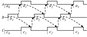
The dashed arrows in Figure 1 indicate the timing constraints of the desynchronized protocol, derived from Cortadella et al.’s marked graph specification; asynchronous controllers are allowed to shift the clock transitions arbitrarily forward and backward in time, as long as those constraints are preserved.222Figure 1 and Cortadella et al.’s proof both assume that all latches start opaque, contrary to the convention used later in this paper (e.g., Figure 4), where odd latches start transparent. It is straightforward to show that these initial states are mutually reachable from each other in the marked graph protocols. We construct a counterexample by delaying the first transitions for latch as long as possible (Figure 2).
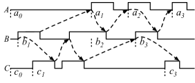
Two circuits are flow-equivalent if the sequences of values stored at their corresponding latches are identical. The trace of values on latch in Figure 2 violates flow equivalence: instead of , the asynchronous circuit latches . Crucially, the second clock pulse of ends before the first pulse of begins. At this point should have latched , but has a transitive data dependency on , which is not yet available.
The error in Cortadella et al.’s proof arises from a subtle misuse of its induction hypothesis. The proof states that, immediately before the second fall of an even latch’s clock (), its predecessor’s clock () must have risen twice, and therefore the induction hypothesis implies that has the value . This is not guaranteed; the induction hypothesis only applies after occurs. It appears that the proof assumes that ’s new value is available as soon as occurs, which, as our counterexample shows, is not necessarily the case.333In fact, the invariant that a new value is always available as soon as a latch becomes transparent is true for the less concurrent fall-decoupled controller, but not for the rise-decoupled or desynchronization controllers, as detailed in Section IV.
The proof contains a similar statement about even predecessors of odd latches, and it is easy to construct a counterexample to illustrate that case. More complex configurations, including cycles, also give rise to counterexamples.
III Formalizing Flow Equivalence
In this section we formalize the definition of flow equivalence in the Coq proof assistant in a way that is amenable to verification later on. Each Coq definition automatically generates an induction principle reflecting the definition’s structure, so different definitions can make proofs easier or harder. Though there are many possible definitions of flow equivalence, the one we present here yields concise and elegant proofs.
Coq is a dependently-typed functional programming language and interactive proof assistant that has been used both to prove significant mathematical theorems [16] and to verify the correctness of realistic software systems [17]. Proof engineers interactively write proof scripts to prove theorems in Coq, from which the system produces a proof term that the Coq kernel can check for validity. Because the kernel is small and trustworthy, the proof scripts used to generate proof terms can be arbitrarily complex and the user can still have confidence that their proof is correct.
We develop the definition of flow equivalence in several stages, illustrating Coq syntax along the way. The resulting formalization could almost certainly be replicated in other provers such as ACL2, Isabelle, or , but Coq’s interactivity, scriptability, and rich inductive definitions were particularly useful in this development.
III-A Synchronous execution semantics
We first define the synchronous execution of a circuit. Like Cortadella et al., we model circuits with master-slave latches obtained by decoupling D flip-flops; every latch is either even (master) or odd (slave), and neighboring latches must have opposite parities.
Let even be a set of even latches and let odd be a set of odd latches. We define the type latch of all latches to be made up of both even and odd latches—mathematically, the disjoint union of odd and even.
\lst@ifdisplaystyleIn the Coq code, the keyword Inductive indicates that latch is defined by its constructors, Odd and Even. Odd is a function of type odd latch, so takes an argument drawn from the set odd, and produces a latch.
A state relative to a type is a function from to values, which are either numbers or undefined.
\lst@ifdisplaystyleDefinition 1 (Circuits).
A circuit consists of lists of neighboring even-odd and odd-even latches, as well as, for each latch, a function that computes its value from the values of its left neighbors. Like Cortadella et al., we model only closed circuits and assume that combinational blocks and latches have zero delay. Any open circuit can be combined with a model of the environment to obtain a closed circuit.
The Record syntax defines a data type with a collection of functions out of that data type. The circuit record has four such functions: eo_nbrs and oe_nbrs are functions from a circuit to lists of its even-odd and odd-even neighbors, respectively; next_e is a function from a circuit, an even latch , and a state of the odd left neighbors of to the next state of ; next_o is similar to next_e, but for odd latches.
In the Record, the notation {x : A & P(x)} restricts the type A to those elements satisfying the predicate P. For example, the next_e function takes as input a state restricted to the odd latches O satisfying the predicate In (O, E) oe_nbrs, where In a ls indicates that the element a occurs in the list ls.
When a latch can be either even or odd, we write for the corresponding next-state function.
Definition 2 (Synchronous Execution).
The synchronous execution of a circuit is a function from the initial state of the circuit to the state at its th clock cycle. In this paper, odd latches update first each clock cycle, followed by even latches.444Without loss of generality, this ordering could be reversed so that even latches update first; the initial markings of the protocols in Figure 4 would need to be updated to reflect that convention. That is:555Note that this definition is well-founded: the values of even latches at time depend on the values of their odd predecessors at time , which themselves depend on the values of their even predecessors at time .
III-B Asynchronous execution semantics
Next, we describe how such a circuit can be executed asynchronously by replacing the shared clock with a series of local clocks controlled by bundled data controllers. This section describes the asynchronous execution semantics with respect to sequences of rising and falling transitions of the local clocks. The allowable sequences are constrained by controller specifications described in Section III-C.
Definition 3 (Events and Traces).
An event is the rise (written ) or fall (written ) of a latch . A trace is a list of events—rises and falls of a latch’s clock. When a latch’s clock rises, the latch becomes transparent; when it falls, the latch becomes opaque.
\lst@ifdisplaystyleA tail_list is either empty, denoted t_empty, or is an element appended onto another tail_list , denoted .
Definition 4 (Transparency).
A transparency characterizes whether a latch is transparent or opaque at a particular point.
The function latch_transp computes the transparency of a latch after executing a trace .
Definition 5 (Asynchronous Execution).
Given an initial state , the asynchronous execution of a trace on a circuit is defined by a 5-ary relation, for which we introduce the syntax . Here, is a latch and is the value of after executing . When this relation holds of a 5-tuple, we say that evaluates to by means of :
-
•
If is transparent in and for all left neighbors of it is the case that , then
-
•
If is opaque in and is the empty list, then .
-
•
If is opaque in and such that , then implies .
-
•
Finally, if and for all left neighbors of it is the case that , then .
Definition 5 has four cases, depending on both the transparency of in and the structure of . This choice of decomposition gives rise to a strong induction principle based on those four cases, which we will use in Section IV to prove flow equivalence.
Figure 3 shows the Coq definition of this relation, extended with an additional parameter corresponding to the transparency of in . The additional parameter makes the Coq relation easier to work with, as we often need to consider only opaque or only transparent latches. Note that function application in Coq is written as the function name (e.g. latch_transp) next to its arguments (e.g. t, l) with whitespace separators.
Each constructor in the Coq definition is a logical formula that indicates when the relation is satisfied. For example, when the trace is empty the circuit is in its initial state: even latches are opaque and they have their corresponding initial values. This property is written , and the Coq proof term async_nil E is evidence that it holds.
III-C Marked graphs
Cortadella et al. characterize the traces allowed by a particular instantiation of controllers as a marked graph, a class of Petri net such that each place has exactly one input and one output transition.
Definition 6 (Marked Graphs).
Given a set of transitions, a marked graph is a set of places, each with associated input and output transitions, with an initial marking—a function from places to natural numbers.
Definition 6 is equivalent to the standard definition of marked graphs as (1) a set of places, (2) a set of transitions, and (3) a flow relation such that each place has unique input and output transitions. However, the type-theoretic Definition 6 enables easier reasoning in Coq. For example, suppose we have a place into in the standard definition. Knowing , there are a finite number of options for , which can be obtained by iterating over the flow relation. Definition 6 does not require this iteration; Coq automatically identifies the possible options for by case analysis.
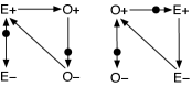
Cortadella et al. describe marked graph protocols with respect to a circuit’s sets of neighboring latches. For each even-odd and odd-even pair they specify the places corresponding to that pair’s rises and falls, as illustrated in Figure 4. The Coq definition of the desynchronization protocol (Figure 4(a)) is shown in Figure 5.
Definition 7 (Enabled Transitions).
A transition is enabled in a marking if all of its input places are positive. An enabled transition can fire to produce a new marking:
A marked graph evaluates to the marking from a tail-list of transitions, written , if the following relation holds:
-
•
If is empty, then .
-
•
If such that and is enabled in , then .
A crucial property of marked graphs is that they preserve the markings of cycles. We write for a path spanning from to , and for the sum of the markings of the places along the path.
Lemma 1.
If is a cycle in a marked graph and , then .
This result follows from the following helper lemma:
Lemma 2.
If is enabled in and , then:
III-D Flow equivalence
Le Guernic et al. [2] define two circuits to be flow-equivalent if and only if (1) they have the same set of latches, and (2) for each latch , the sequence of values latched by is the same in both circuits. It need not be the case that the two circuits have the same state at any specific point in time, but the projection of the states onto each latch should be the same. This ensures that, even if the timing behaviors of the two circuits differ, their functional behaviors are the same.
In this case, we are interested in comparing the same circuit under two different execution models: synchronous and asynchronous. For the synchronous model, the projection of the values latched by a latch are given by the function . For the asynchronous model, we have to consider the execution of every trace allowed by the asynchronous controller.
Definition 8 (Flow Equivalence).
A marked graph ensures flow equivalence of a circuit with initial state if every trace allowable by the marked graph has the same synchronous and asynchronous execution. That is, let be a trace compatible with , and let be a latch, opaque in , such that . Then is the th value of the synchronous execution of , where , the number of occurrences of in .
IV Verified Flow-Equivalent Protocols
In this section we prove in Coq that the rise-decoupled and fall-decoupled protocols illustrated in Figure 4 preserve flow equivalence, and revisit the counterexample of Section II in the context of the formalization.
IV-A Rise-decoupled protocol
The rise-decoupled protocol, also called fully-decoupled [18] and illustrated in Figure 4(b), preserves the invariant that when is latched for the th time, its predecessors have also been latched the appropriate number of times (either or times); thus, correctly latches its th synchronous value. Figure 6 illustrates several possible interleavings of neighboring latches that satisfy the rise-decoupled protocol. Notice that may not acquire its correct value by the th occurrence of , but it will by the th occurrence of .
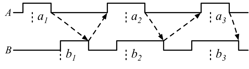
Fix a circuit and an initial state . The definition of the rise_decoupled marked graph with respect to is omitted here for space, but is similar that of the desynchronization protocol shown in Figure 5. In the Coq definition, we add two redundant arcs to ensure that there are always arcs from to and vice versa. Since there is at most one place between two events and , we write for that place when it exists.
To prove that the rise-decoupled protocol preserves flow equivalence, we first prove several lemmas about the rise-decoupled marked graph.
Lemma 3.
Let . If has a right neighbor such that , then is opaque in .
Proof.
By induction on . Using Lemma 1 and some light automation (about 50 lines of Coq tactics that will be re-used for other proofs), this lemma is proved in fewer than 20 lines of Coq proof scripts. ∎
Next, we prove a lemma relating the number of occurrences of in a trace for neighboring latches.
Lemma 4.
Let . If is enabled in , then for all left neighbors of ,
Proof.
The induction hypothesis must be strengthened to account for three exhaustive cases: ; ; and . These cases are exhaustive because of Lemma 1: the sum of these three values is exactly equal to . The proof then proceeds by induction on . ∎
Finally, we can prove the main result, that rise_decoupled satisfies flow equivalence.
\lst@ifdisplaystyleRecall that we have already fixed the circuit and initial state and that the definition of the rise_decoupled marked graph depends on .
Unfolding the definition of flow equivalence, we can write out the statement of the theorem in English:
Theorem 5.
If such that is opaque in and , then .
Proof.
By induction on the asynchronous evaluation judgment . The structure of that definition leads to an induction principle with four cases.
-
wide
The first case, where is transparent in , is vacuous.
-
wiide
If is the empty trace it suffices to consider only even latches, for which the result is immediate.
-
wiiide
If such that , the result follows immediately from the induction hypothesis.
-
wivde
Finally, the only non-trivial case is when . Since is enabled, its left neighbors are all opaque and so have already acquired their correct values.
In this case, where, for all left neighbors of , . Since is enabled in , is opaque in (Lemma 3). Thus the induction hypothesis applies:
Unfolding definitions,
where, for all left neighbors of ,
and where . The fact that follows from Lemma 4. ∎
Note that we could have performed induction on the trace here, but that would not be sufficient for the fall-decoupled proof, which requires us to reason about both transparent and opaque latches.
IV-B Fall-decoupled protocol
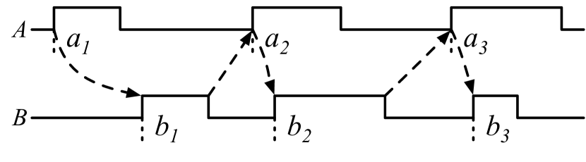
The rise-decoupled protocol of the previous section allows the rises of clocks to interleave arbitrarily as long as the falls of those clocks obey the inductive invariant. In the fall-decoupled protocol (Figure 4(b)), the situation is reversed—a clock may fall either before or after its predecessors’ clocks fall, as long as its rise occurs after its predecessors’ clocks rise, as illustrated in Figure 7. Under the zero-delay assumption, the model preserves the invariant that each latch will obtain its correct value as soon as it goes transparent, and that value will be stable until it goes opaque again.
For the proof of flow equivalence, we build on the same structure of lemmas as for the rise-decoupled protocols, proving variants of Lemmas 3 and 4 adapted to the fall-decoupled protocol. For example:
Lemma 6.
Let . If is opaque in , then
If is transparent in , then for all left neighbors of :
In the rise-decoupled protocol, the proof of flow equivalence relies on the fact that, whenever the event is enabled, all of ’s left neighbors are opaque, so are guaranteed to have their correct values. This is not the case in the fall-decoupled protocol, where ’s left neighbors might be either transparent or opaque. Therefore, it is necessary to strengthen the statement of flow equivalence to account for the values of both opaque and transparent latches.
Theorem 7.
If and , then , where
Proof.
By induction on the relation .
-
wide
First, if is transparent in , then is equal to such that, for all left neighbors of , .
Notice that : for odd this follows immediately from the definition; for even there is at least one occurrence of in since even latches are initially opaque. Thus, where .
It suffices to show that for all left neighbors , . By induction, where
By Lemma 6 we know that , which completes the proof.
-
wiide
If is opaque in the empty trace, it must be odd, and the result is trivial.
-
wiiide
If is opaque in where , the result is straightforward from the induction hypothesis on .
-
wivde
Finally, if , then where for all left neighbors of . Furthermore, is equal to where . So it suffices to show that, for all left neighbors , . By the induction hypothesis , where
By Lemma 6 we know , as required. ∎
Finally, we must show that Theorem 7 implies flow equivalence.
Corollary 8.
Whenever such that is opaque in and , then where .
Proof.
IV-C Less concurrent protocols
Cortadella et al. also discuss three other protocols that are even less concurrent than the rise-decoupled and fall-decoupled protocols, and claim they are flow equivalent since every trace they accept is also accepted by a known flow-equivalent protocol. Because they are all three subsumed by the rise- and fall-decoupled protocols, this is still true in our case. The formal proofs of this result depend only on the proof that one marked graph refines another. As an exercise, we proved this fact for the semi-decoupled protocol in our Coq repository.
IV-D Counterexample, revisited
Finally, we revisit the counterexample to desynchronization described in Section II in the formal setting, providing a concrete circuit and a trace compatible with desynchronization such that, after executing the trace, there is a latch whose value is not equal to . The proof of flow equivalence fails in this case because neither of the inductive invariants described in the rise-decoupled or fall-decoupled protocols are satisfied—the desynchronization protocol allows latches to go opaque before all of their left neighbors have gone opaque, which can result in an entire value being dropped, as in Figure 2.
Theorem 9.
There exists a circuit for which the desynchronization protocol does not ensure flow equivalence.
Proof.
Figure 8 shows a three-stage pipeline, similar to the one in Section II but with two additional latches SRC and SNK representing the input and output environments respectively. In the initial state, all latches have value , and with each pulse, the source environment SRC sends integers of increasing value to . Each pipeline stage increments its input by one (denoted inc_value v), and the output environment SNK consumes the output of .
We take a prefix of the trace illustrated in Figure 2 up until the second fall of ’s clock. It is at this point that flow equivalence is violated—the second value latched by is still .
It is easy to check that there exists a marking such that , and that . To complete the proof that flow equivalence is violated, it suffices to check that . ∎
V Summary and Future Work
This paper makes three contributions: we identify a mistake in a hand-written proof, carefully formalize the relevant definitions, and adapt the proof to two variants of the original protocol. This research highlights the benefits of formal theorem proving to verify that a design satisfies desirable properties.
Future work will apply this framework to verify the correctness of gate-level implementations of the controllers by checking that they satisfy the rise- or fall-decoupled protocols. In addition, we plan to extend our Coq framework to account for more abstract design specifications such as FF-based synchronous designs and CSP-like specifications, as well as more realistic delay models. A long-term goal is to develop a comprehensive assurance framework for desynchronization-based design flows, which would account for the correctness of retimed datapaths and liveness. These extensions may require bridging disparate formal frameworks, including static timing analysis, equivalence, and model checking.
Acknowledgment
Thanks to Marly Roncken, Ivan Sutherland, Tynan McAuley, Flemming Anderson, and the anonymous reviewers for their helpful feedback. This material is based upon work supported by the Defense Advanced Research Projects Agency (DARPA) under Contract No. HR0011-19-C-0070. The views, opinions, and/or findings expressed are those of the authors and should not be interpreted as representing the official views or policies of the Department of Defense or the U.S. Government. DARPA Distribution Statement “A” (Approved for Public Release, Distribution Unlimited).
References
- Cortadella et al. [2006] J. Cortadella, A. Kondratyev, L. Lavagno, and C. P. Sotiriou, “Desynchronization: Synthesis of asynchronous circuits from synchronous specifications,” IEEE TCAD, vol. 25, no. 10, pp. 1904–1921, Oct 2006.
- Le Guernic et al. [2003] P. Le Guernic, J.-P. Talpin, and J.-C. Le Lann, “Polychrony for system design,” Journal of Circuits, Systems and Computers, vol. 12, no. 3, pp. 261–303, 2003.
- The Coq Development Team [2019] The Coq Development Team, “The Coq proof assistant, version 8.10.0,” Oct. 2019, DOI: 10.5281/zenodo.3476303.
- Nelson et al. [2007] C. Nelson, C. Myers, and T. Yoneda, “Efficient verification of hazard-freedom in gate-level timed asynchronous circuits,” IEEE TCAD, vol. 26, no. 3, pp. 592–605, 2007.
- Verbeek et al. [2013] F. Verbeek, S. Joosten, and J. Schmaltz, “Formal deadlock verification for Click circuits,” in Proc. ASYNC, May 2013, pp. 183–190.
- Cunningham [2004] P. A. Cunningham, “Verification of asynchronous circuits,” University of Cambridge, Tech. Rep. UCAM-CL-TR-587, 2004.
- Park et al. [2016] H. Park, A. He, M. Roncken, X. Song, and I. Sutherland, “Modular timing constraints for delay-insensitive systems,” Journal of Computer Science and Technology, vol. 31, pp. 77–106, Jan. 2016.
- Longfield and Manohar [2013] S. Longfield and R. Manohar, “Inverting Martin Synthesis for verification,” in Proc. ASYNC, 2013, pp. 150–157.
- Sakib et al. [2019] A. A. Sakib, S. C. Smith, and S. K. Srinivasan, “Formal modeling and verification of PCHB asynchronous circuits,” IEEE TVLSI, pp. 1–14, 2019.
- Saifhashemi et al. [2015] A. Saifhashemi, H. Huang, P. Bhalerao, and P. A. Beerel, “Logical equivalence checking of asynchronous circuits using commercial tools,” in Proc. DATE, March 2015, pp. 1563–1566.
- Bui et al. [2012] T. Bui, T. Nguyen, and A.-V. Dinh-Duc, “Experiences with representations and verification for asynchronous circuits,” in Proc. ICCE, 2012, pp. 459–464.
- Borrione et al. [2003] D. Borrione, M. Boubekeur, E. Dumitrescu, M. Renaudin, J.-B. Rigaud, and S. Sirianni, “An approach to the introduction of formal validation in an asynchronous circuit design flow,” in Proc. HICCS, 2003.
- Bouzafour et al. [2018] A. Bouzafour, M. Renaudin, H. Garavel, R. Mateescu, and W. Serwe, “Model-checking synthesizable SystemVerilog descriptions of asynchronous circuits,” in Proc. ASYNC, May 2018, pp. 34–42.
- Peng and Greenstreet [2019] Y. Peng and M. Greenstreet, “Verifying timed, asynchronous circuits using ACL2,” in Proc. ASYNC, May 2019, pp. 96–104.
- Chau et al. [2019] C. Chau, W. A. Hunt, M. Kaufmann, M. Roncken, and I. Sutherland, “A hierarchical approach to self-timed circuit verification,” in Proc. ASYNC, May 2019, pp. 105–113.
- Gonthier [2008] G. Gonthier, “Formal proof–the four-color theorem,” Notices of the AMS, vol. 55, no. 11, pp. 1382–1393, 2008.
- Leroy et al. [2012] X. Leroy et al., “The CompCert verified compiler,” Documentation and user’s manual. INRIA Paris-Rocquencourt, vol. 53, 2012.
- Furber and Day [1996] S. B. Furber and P. Day, “Four-phase micropipeline latch control circuits,” IEEE TVLSI, vol. 4, no. 2, pp. 247–253, June 1996.