Ultrafast antiferromagnetic switching in NiO induced by spin transfer torques
Abstract
\ceNiO is a prototypical antiferromagnet with a characteristic resonance frequency in the THz range. From atomistic spin dynamics simulations that take into account the crystallographic structure of NiO, and in particular a magnetic anisotropy respecting its symmetry, we describe antiferromagnetic switching at THz frequency by a spin transfer torque mechanism. Sub-picosecond S-state switching between the six allowed stable spin directions is found for reasonably achievable spin currents, like those generated by laser induced ultrafast demagnetization. A simple procedure for picosecond writing of a six-state memory is described, thus opening the possibility to speed up current logic of electronic devices by several orders of magnitude.
I Introduction
Nature provides us with a variety of magnetic textures, and antiferromagnetism occurs commonly among transition metal compounds, especially oxides. It consists in a local combination of magnetic moments of several ions in crystalline sublattices to produce a vanishing total magnetization. Such antiferromagnetic (AF) materials display several interesting characteristics including robustness against external magnetic perturbations, long coherence times, which make them suitable candidates for quantum computing Duong et al. (2004); Meier et al. (2003), and picosecond dynamics. All these advantages make them promising for a new generation of ultrafast spintronic devices Jungwirth et al. (2016); MacDonald and Tsoi (2011); Gomonay and Loktev (2014); Gomonay et al. (2016). Indeed, thanks to the antiferromagnetic exchange enhancement Gomonay and Loktev (2015); Gomonay et al. (2018), the resonance frequency depends both on and (respectively the exchange and the anisotropy frequencies, defined from their corresponding energy divided by the reduced Plank constant ). This is to be compared with only for the case of ferromagnets Keffer and Kittel (1952); Sievers and Tinkham (1963); Cheng et al. (2015). When , it is proportional to , which is generally two orders of magnitude faster than that for ferromagnets with the same anisotropy frequency. Therefore, interesting applications can be envisioned from this dynamical behavior, including building magnetic oscillators in the T Hz range and fast-switching memories Cheng et al. (2015); Khymyn et al. (2017). Such devices would be robust against external magnetic fields and compatible with todays oxide technologies deployed in spintronics.
The past ten years have seen a surge of interest, mainly at a fundamental level, to bring proofs of concept for using antiferromagnets as memory devices. Early theories targeted metals Núñez et al. (2006); Haney et al. (2007); Duine et al. (2007) and inspired their validation as memory devices Marrows (2016); Wadley et al. (2016). However, insulators may be better candidates as they exhibit lower magnetization damping and can conduct spin currents Hahn et al. (2014); Wang et al. (2015); Lebrun et al. (2018); Baldrati et al. (2019). Many materials are candidates for building memory devices, but so far \ceNiO has been the focus of many studies because it is considered as an archetype for room-temperature applications. Nevertheless, its full crystallographic form has seldom been considered as far as spintronic applications are concerned, probably because dealing in detail with the full magnetic anisotropy landscape can be cumbersome. Indeed, a single T-domain \ceNiO is often approximated as an easy plane compound with a weaker single in-plane easy axis along Cheng et al. (2015); Hutchings and Samuelsen (1972); Mondal et al. (2019). It is nonetheless known that this type of domain in \ceNiO possesses a sixfold degenerate magnetic state within the easy plane Uchida et al. (1967). This offers a richer switching behavior and also the possibility to build a six-state memory element (or at least with three readable states, as domains may be hard to distinguish Baltz et al. (2018)). The present work aims to harvest these properties by investigating theoretically the magnetic control of the sixfold symmetry using spin transfer torques.
Experimentally, very recent works have studied the possible influence of a spin injection on the domain structure of thin \ceNiO layers. Spins are usually injected by the spin-orbit torque effect using a Pt layer deposited on top of the \ceNiO film. When a charge current flows in the Pt, the generated transverse spin current induces a non-equilibrium spin accumulation at the \ceNiO/Pt interface. This planar geometry is adequate for the spin Hall effect, but restrictive in terms of the direction of the injected spins. Moreover, the required current densities generate a substantial amount of heat in the structure that may also perturb the AF order. We suggest here a different procedure that relies on the spin injection via ultrafast demagnetization of an adjacent ferromagnetic (FM) layer by an intense femtosecond laser pulse. This generates the fastest and strongest spin pulses available so far Kampfrath et al. (2010, 2013), with the extra functionality of setting at will the spin direction in three dimensions (by simply setting the FM magnetization). Several parameters have to be adjusted in order to optimize the switching mechanism in the \ceNiO layer and it is important to identify the most relevant ones, resulting in both the lowest STT amplitude and the fastest AF switch. Therefore, the present paper describes the coherent switching processes induced by an ultrafast laser-generated spin transfer torque in a memory element made of a bi-layer \ceNiO/FM. Our approach relies on numerical atomistic simulations, where the sixfold symmetry of the \ceNiO magnetic anisotropy is taken into account.
II \ceNiO crystal structure and magnetic anisotropy
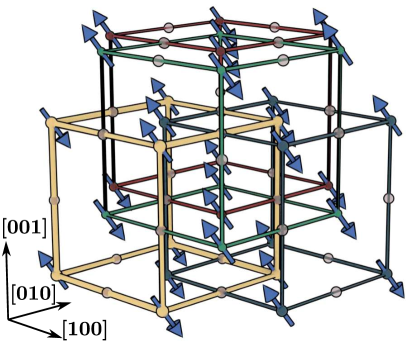
At room temperature, \ceNiO adopts a fcc structure with and at the octahedral sites, altered by a slight rhombohedral contraction along one of the four directions. This leads to the formation of four possible twin domains (T-domains) in \ceNiO crystals Hutchings and Samuelsen (1972). In a given T-domain, the magnetic moments of the nickel ions are subject to various superexchange interactions related to the arrangement of the neighboring oxygen ions. They consist in a strong antiferromagnetic coupling at with the six second nearest neighbor (nnn) atoms, as well as a weak ferromagnetic coupling at with the twelve nearest neighbors (nn) atoms, resulting overall in G-type antiferromagnetism with a staggered order along the direction, along which ferromagnetic sheets are stacked Hutchings and Samuelsen (1972). The associated exchange energies are for the 6 (spin parallel) next nearest neighbors, for the 6 (spin parallel) in-(111)-plane nearest neighbors, and for the 6 (spin antiparallel) out-of-(111)-plane nearest neighbors Hutchings and Samuelsen (1972). The nnn-superexchange being by far the strongest, we neglect here the influence of the nearest neighbor interactions, which is equivalent to considering only one of the four equivalent sublattices shown in Fig. 1. Even if the nearest neighbor coupling may slightly enrich the magnetization dynamics, it is considered negligible and is not treated in the frame of the present paper.
 |
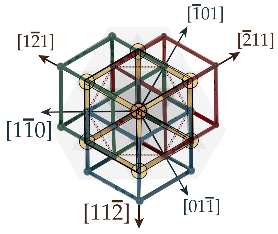 |
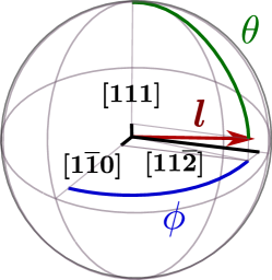
Within one T-domain, \ceNiO exhibits an anisotropy pattern with a hard axis along , and three easy axes along , and (right panel of Fig. 1), defining three possible S-states, and 6 possible spin orientations. This configuration is modeled in regard to the symmetry of the crystal by taking the expansion of the rhombohedral anisotropy energy to its leading orders in out-of-plane () and in-plane () components. Using spherical coordinates in the frame based on the orthogonal axes , and , the effective anisotropy energy for a given spin is written as Bogdanov and Dragunov (1998); Skomski et al. (2008)
| (1) |
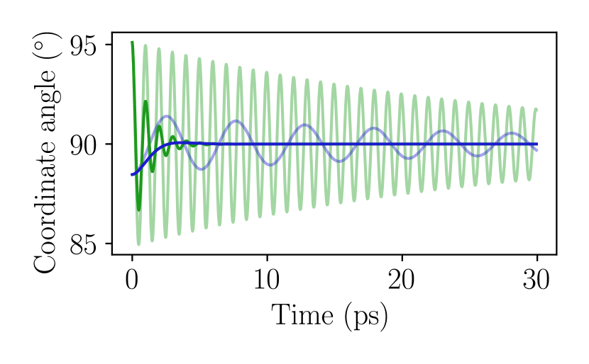
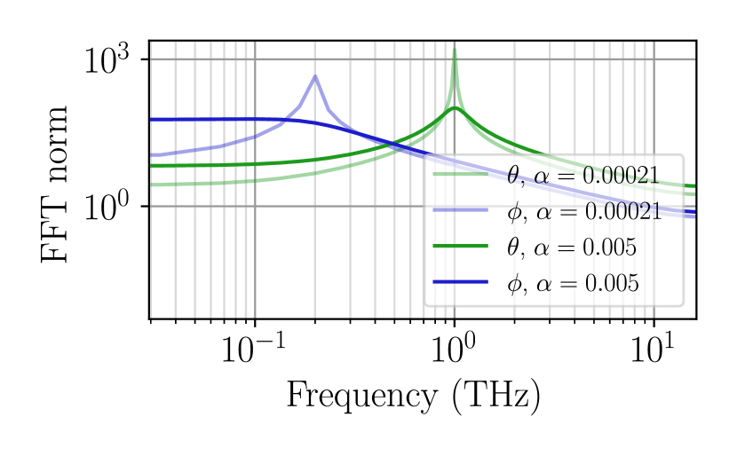
The values of the anisotropy constants are adjusted dynamically, based on the resonances observed experimentally for \ceNiO in references Kampfrath et al. (2010); Sievers and Tinkham (1963); Satoh et al. (2010); Baierl et al. (2016); Kohmoto and Moriyasu (2018); Milano et al. (2004); Cheng et al. (2015). For that purpose, we define the Néel vector associated to a set of two spins representing the two antiferromagnetic sublattices, and tilt it slightly from its rest position. A simulation is then performed based on the dynamic model detailed in the next section, with an effective damping parameter to accommodate specifically the experimental measurements of Kampfrath et al. Kampfrath et al. (2010). It leads to damped oscillations towards equilibrium with the two expected characteristic frequencies of and when the anisotropy constants are adjusted to and , as shown in Fig. 2.
With these values, the difference in energy between the and directions is then (per atom), and the energy barrier between two stable neighboring orientations at to one another is (per atom). This latter energy is experimentally difficult to measure because any unrelaxed strain induces a sample dependent larger anisotropy Kurosawa et al. (1980), but the former one is of the same order of magnitude as the one found e.g. in inelastic neutron scattering experiments () Hutchings and Samuelsen (1972). The energy barrier for a coherent switching of a typical AFM containing roughly atoms is evaluated to hundreds of kelvin, which justifies that thermal fluctuations can be neglected in the present simulations. Based on this description, we will show that magnetic S-states can be dynamically switched under spin current pulses that are experimentally achievable by ultrafast demagnetization processes using femtosecond lasers pulses.
III Dynamic model
The spin dynamics of antiferromagnets can be described approximately by a set of two coupled Landau Lifshitz Gilbert (LLG) precession equations linking two sublattices of equivalent magnetization Chikazumi (1997). In the case of \ceNiO, it has been predicted theoretically that a spin current should produce a spin transfer torque (STT) acting similarly on the two sublattices and resulting in a significant torque on the Néel vector Gomonay and Loktev (2010); Cheng et al. (2014); Khymyn et al. (2017). In order to tackle the dynamics of this antiferromagnetic order, we consider two coupled atomistic equations of motion, one for each equivalent magnetic sublattice labeled by , an unitary vector, that can be formulated as follows Tranchida et al. (2018):
| (2) |
By denoting the vacuum permeability and the gyromagnetic ratio, the effective magnetic field on each sublattice is a functional of , where is composed of the sum of the anisotropy field , the exchange field and the spin torque, altered by a damping :
| (3) | ||||
| (4) |
In detail, each contribution decomposes as follows:
Anisotropy field:
Exchange field:
Spin torque:
represents the frequency in the Slonczewski’s spin transfer torque expression Slonczewski (1996); Gomonay and Loktev (2010). For a STT (expressed in ) injected though a thin layer of \ceNiO from an adjacent ferromagnetic layer, we can estimate it as:
| (7) |
where is the spin transparency of the interface, the lattice constant, the number of magnetic atoms per unit cell, the layer thickness and vector is parallel to the spin current polarization, with a magnitude equal to the spin current density. In the present paper, values are expressed directly in spin currents taking , , and . The \ceNiO thickness is optimally taken close to the experimentally estimated penetration depth of spin-polarized electrons Hahn et al. (2014); Wang et al. (2015).
For all the following simulations, which involve thin films, the damping value is set to . This value is higher than the one used to adjust the resonances, which corresponded to a value typically found in bulk samples. With this higher value, we also expect to account for several additional mechanisms, including for example the spin dissipation induced by an adjacent ferromagnetic layer. This value appears sufficient to capture a broad range of possible effects encountered in thin films spintronics (even though we recognize that the Gilbert form here adopted is not quite proper to accurately account for inter-lattice dissipations Kamra et al. (2018)).
 |
 |
 |
IV Results and discussion
Within this dynamic model for \ceNiO, a STT applied along the direction of a T-domain can trigger a change of orientation of the spins, switching from one S-state to another. This is the case studied analytically by Cheng et al. Cheng et al. (2015) albeit in an orthorhombic symmetry. Our anisotropy profile exhibits the 6 possible stable orientations, and a switch between them can be achieved in a picosecond timescale, as revealed by the Fig. 3.
 |
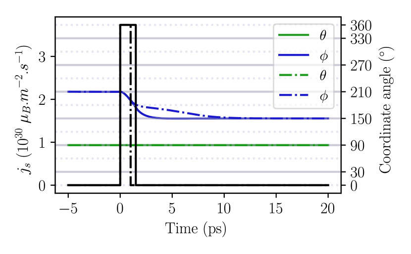 |
Due to the presence of intermediate stable positions, the minimum duration of STT needed to achieve a switch is significantly reduced compared to the one predicted in ref. Cheng et al. (2015). For the same spin current value of considered in this reference, the minimum duration is reevaluated from to . Even shorter switches can be achieved when reorienting the spins by . In this case, the duration of the STT pulse can be reduced even to , with the same intensity.
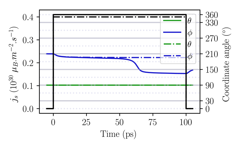
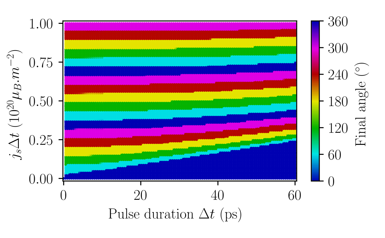
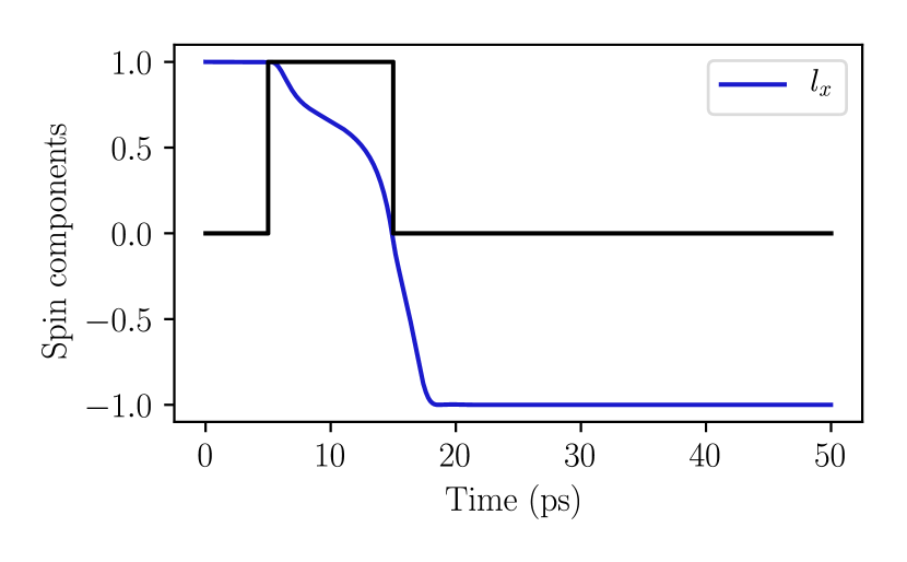
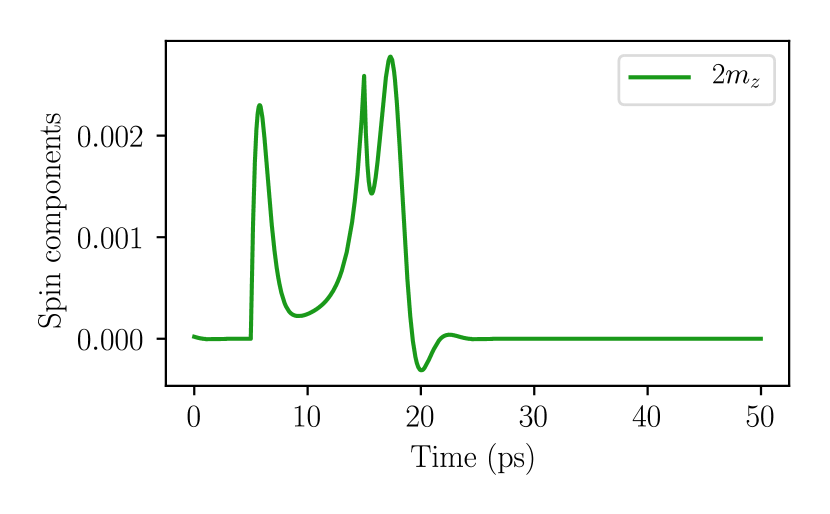
As the threshold for switching is directly linked to the anisotropy value, the lowest STT amplitude is obtained when the \ceNiO spin trajectories remain in the easy plane. This is indeed achieved when the spin current is polarized along the direction and for a threshold close to , as shown in Fig. 4. As long as the STT excitation exceeds the threshold, precession occurs at a frequency depending on how much the system is driven above the threshold, as well as its natural timescale and damping. Once the spin pumping is turned off, the system precesses permanently for zero damping, whereas it falls quickly to an equilibrium position for large damping. For the realistic value of and by providing a suitable spin pulse strength and duration, all the in-plane equilibrium angles can be reached at will in some picoseconds. Interestingly, it is in principle possible to apply a bipolar spin current pulses in order to fall more reliably into the chosen position.
Some simple expectations can also be inferred directly from the differential equations of motion of the angular dependence of the Néel vector, as shown in appendix B. Firstly, as far as writing speed is targeted, one may realize that for STT pulses sufficiently fast not to lose too much angular momentum in damping processes, i.e. much faster than , only the total number of injected spins matters. Indeed, in that case the STT cants the two sublattices with a characteristic time of , as shown in Fig.5. This stores in the system’s magnetization a quantity of exchange energy proportional to the number of injected spins. Once the driving is turned off, this energy drives the precessional motion of the Néel vector at its natural precession frequency , until the damping fully stops the precession. This dynamics is quite similar to what was predicted for noncollinear antiferromagnets Gomonay and Loktev (2015); Kimel et al. (2009).
The horizontal lines on Fig. 6 show that the requirement to reach a given memory state, depends only on the total number of injected spins , for far above the threshold value (for a thick \ceNiO).
One can conclude that for pulses faster than a few picoseconds, no pulse shaping is necessary and the only parameter governing the switching is the total number of injected spins. Therefore, the injection can be achieved in an arbitrarily short period of time: the shorter the pulse duration is, the stronger the STT strength must be, as shown in Fig. 7. After the injection, the dynamics proceeds, until all the accumulated STT energy stored in the canting is damped, on a timescale determined by . Consequently, a bit of information can take less than a fraction of picoseconds to reach a new value, depending on how far from equilibrium the STT ends. Nonetheless, the final rest time to reach a stable state is incompressible and depends on the damping value. As far as stabilization speed is concerned, a too low damping is therefore not desirable, and a value higher than 0.005 should be optimal Cheng et al. (2015). One could then envision to write a logical bit very fast, but a few picoseconds waiting time must be observed before the bit acquires stability. As the total rest time is set by the damping, it is not possible to shorten the total switching procedure. Another option to improve fast switching would be to use tailored shaped bipolar pulses to reduce quickly to zero the inertia stored in the spin canting and force the system to reach an equilibrium minimizing the ringing. This subpicosecond fine tuning, however, seems presently out of reach experimentally.
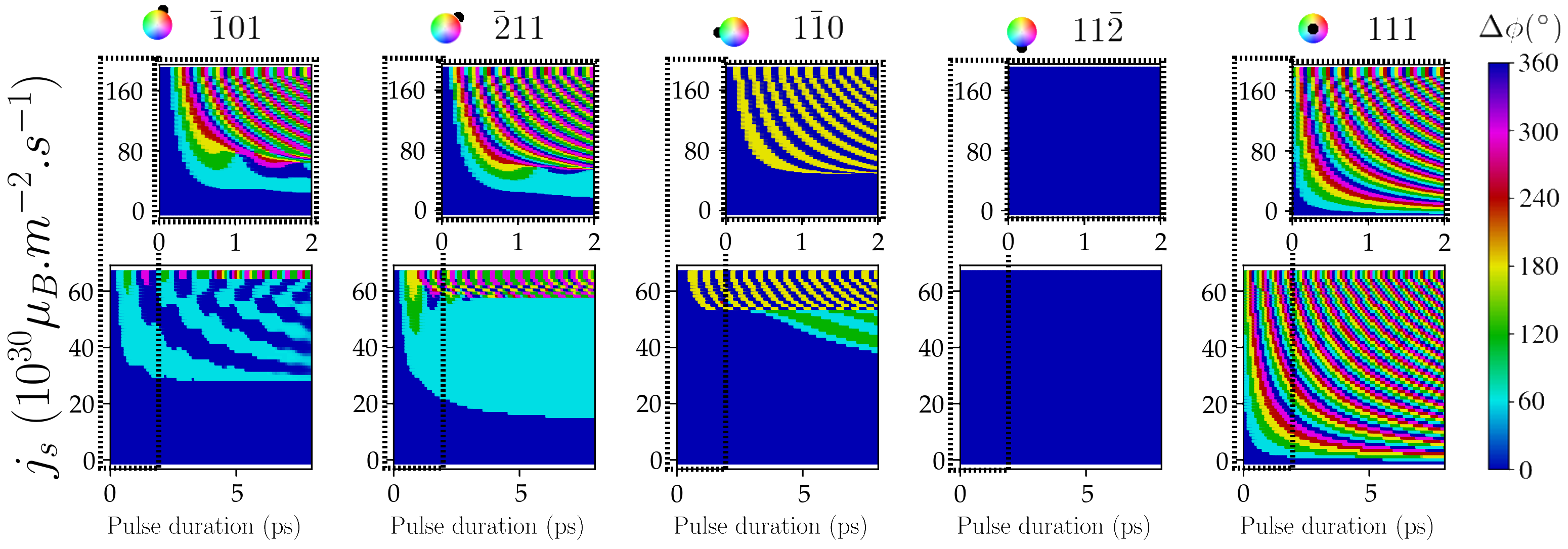
Moreover, fully deterministic switching is a particularly difficult problem Chen et al. (2018). This stems from the absence of the internal self-stabilization mechanism present in ferromagnets Chen et al. (2018). In this respect, it is instructive to consider other directions for the STT to force the AF vector to take a trajectory through higher anisotropy energies, as shown in Fig. 7. There, the final states for a along one of the main in-plane axes are displayed. For directions other than , the threshold values are much higher and often experimentally out of reach. Especially when the STT is applied parallel to the spins direction (), the excited mode generally generates a cone of precession much smaller than , which does not lead to switching. For the other directions, the spins tend to precess around the STT, but with trajectories constrained by the anisotropy profile. Precessing out of the easy plane requires more energy, as can be seen in Fig. 7 for the direction. STT directions at or to the spin are more efficient. Indeed, they generate a sufficiently small precession cone to remain close to the easy plane. When at (direction ), the spins can easily oscillate between the two neighboring positions. Finally, the direction at (direction ) is particularly interesting for controlled writing application. There, the STT causes a sufficiently large precession to induce a switch, with a trajectory experiencing a reduced torque as it gets close to the STT axis. This enhances a more efficient trapping from the stable state along the STT, as visible on the corresponding diagram of Fig. 7.
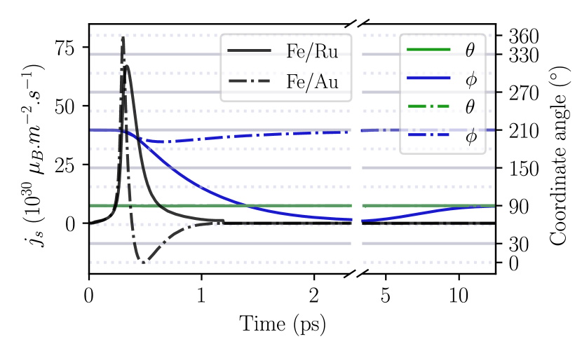
In the light of the present simulations, it is important to assess whether or not the conditions for writing such a memory could be achieved experimentally. The shortest spin transfer torque stimulus experimentally available is that generated by the ultrafast demagnetization of a ferromagnetic layer by a femtosecond laser pulse Kampfrath et al. (2013). Emitted from the ferromagnetic layers, bursts of spins have been injected into different metals using double layers (e.g. \ceFe/Ru or \ceFe/Au), where their spin conversion generates a T Hz pulse of electric charge. Hence, the heavy metal layer acts as a sensor for the spin current burst. Using the two reported shapes, we run our simulations in order to estimate if this technique can be adequate for addressing a memory element made of NiO. The results, displayed in Fig. 8, indicate that the unipolar spin burst generated in a \ceFe/Ru structure applied in the direction of \ceNiO, can effectively switch the Néel vector to another stable position. On the other hand, the bipolar pulse of the \ceFe/Au structure cannot. This is consistent with our previous observation that for such short pulses, only the total amount of injected spins is relevant. For the bipolar pulse, this quantity is too small.
This is therefore an encouraging result, although a real spin current shape cannot be directly inferred from those observed in metallic double layers. A more realistic \ceCoFeB/\ceNiO system should be tested as the spin injection efficiency should be reduced because of a poorer interface transparency. Nevertheless, as the minimum number of injected spins for switching is four times below that of the experimental spin bursts in \ceFe/Ru, our simulations indicate that very fast switching should be possible in \ceNiO, when an adjacent ferromagnetic layer is subjected to ultrafast demagnetization.
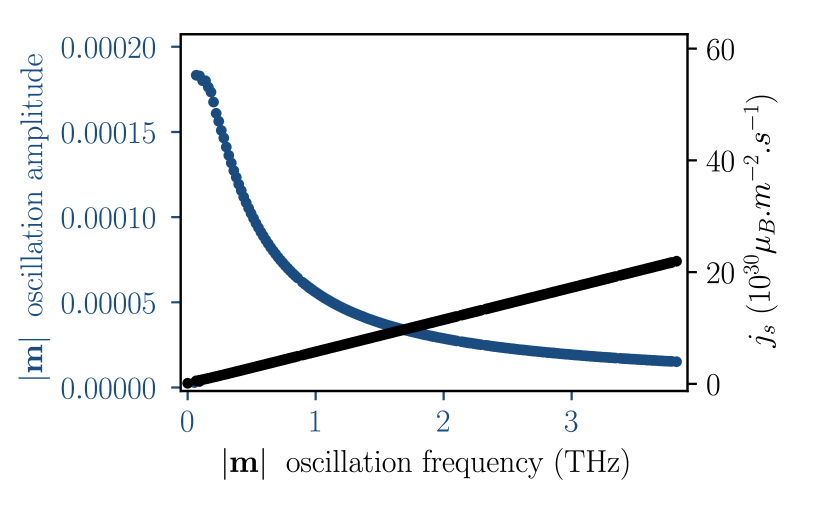
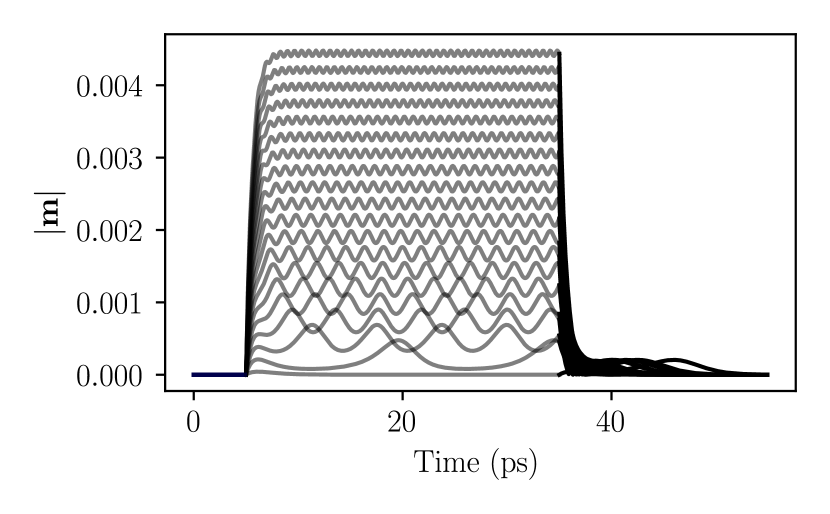
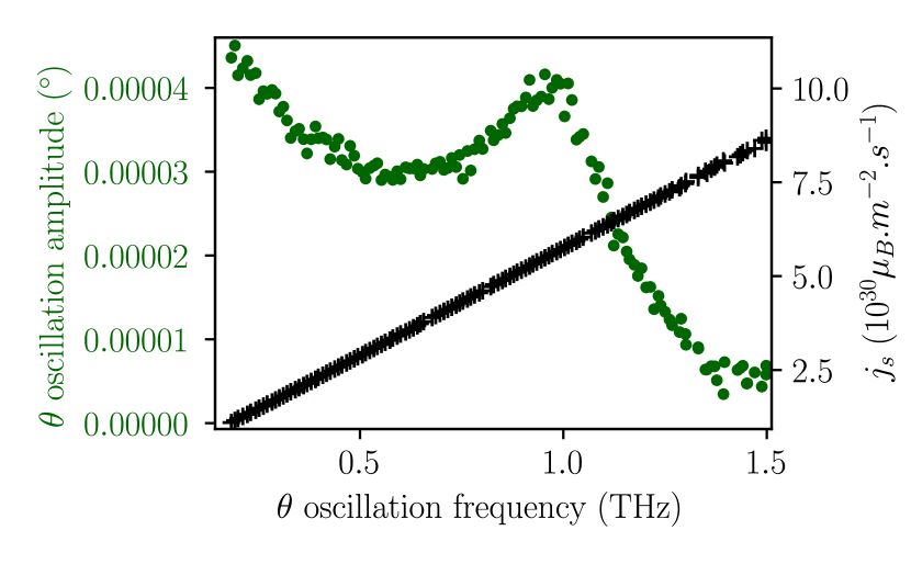
Finally, similar systems can also be used for oscillators, as reported in reference Khymyn et al. (2017). In that case, the characteristic setting time must be taken into account before observing stable oscillations. Fig.5 and 9 show the behavior of the uncompensated magnetization when the \ceNiO is pumped with long duration pulses. The frequency of the oscillations varies linearly with the spin current intensity and can be hypothetically adjusted at will. Nonetheless, the amplitude of the oscillations tends to be higher for low spin current intensities. For the low currents just above the threshold, spikes periodically with high amplitude. For these values, indeed undergoes rapid accelerations when passing , but the pace is low since it is slowed down every time it passes the anisotropy barriers near . Hence, the duty cycle is reduced and the harmonicity is degraded. This can be seen as a periodical pulses generation. As shown on Fig. 10, the mode at is excited by the out-of plane excursion of during its in-plane rotation.
Conclusion
By performing atomistic spin simulations, we have shown that a thin layer of \ceNiO can in principle be used to build a six-state memory device. By using magnetic anisotropy expressions that reflect the real symmetries of the material, we have exhibited that experimentally available sub-picosecond pulses are a priori adequate to switch a thick memory element. Thus, we propose a device formed by a \ceNiO/ferromagnetic double layer, where an ultrafast laser is used to inject a spin population at an arbitrary spin angle, by demagnetizing the ferromagnetic layer. Both constraints on the growth of epitaxial \ceNiO, as well as on the control of the STT direction are then released by this technique. The excitation process offers the possibility to access deterministically the six AF spin states at picoseconds time scale. Beyond memory devices, the non-trivial magnetic anisotropy of \ceNiO suggests a richer dynamics that could lead to other spintronic applications in the T Hz range.
Acknowledgements.
We wish to acknowledge Julien Tranchida for the fruitful discussions, and the French National Research Agency for support with the project ANR SANTA (Grant No.ANR-18-CE24-0018-03). O.G. acknowledges the Alexander von Humboldt Foundation, the ERC Synergy Grant SC2 (No.610115) and funding by the Deutsche Forschungsgemeinschaft (DFG, German Research Foundation) - TRR 173 - 268565370 (project B12).Appendix A Numerical implementation
Simulations are performed for two spins that are coupled with effective fields. Each spin represents its own ferromagnetic sublattice. The equations of precession are integrated in time with a symplectic integrator. The transverse equation (2) is discretized to update only the orientation of each spin for a given timestep . In practice, is computed from and with precision Tranchida et al. (2018), according to:
| (8) |
To check the consistence of this approach, we evaluate the dynamics of the Néel vector and average magnetization by using the numerical values found in reference Cheng et al. (2015); Nussle et al. (2019). Our simulations reproduce well the published results as shown in Fig. 11.
 |
 |
The simulations in the core of the paper were done with a time step of , on a total of two atoms only, with an exchange value accounted 6 times, which is equivalent to periodic boundary conditions in all directions, for the given superexchange sublattice.
Appendix B Raising time in an uniaxial anisotropy
By considering a sixfold easy axis ( along ) in a hard plane ( along ), as long as , the equation for reduces to a one dimensional problem Cheng et al. (2015); Gomonay et al. (2018); Yamane et al. (2019):
| (9) |
with . The out-of-plane component of the magnetization vector is simply . With and by considering the response near the beginning of the pulse, for which , the previous differential equation is linearized, so that:
| (10) |
and solved, after defining . We find
| (11) |
Therefore near ,
| (12) |
meaning that from reference Khymyn et al. (2017), a simple model for the convergence to the average value of the angular velocity gives , which is in agreement with our numerical simulations, as depicted in Fig. 5 in section IV.
References
- Duong et al. (2004) N. P. Duong, T. Satoh, and M. Fiebig, Phys. Rev. Lett. 93, 117402 (2004).
- Meier et al. (2003) F. Meier, J. Levy, and D. Loss, Physical Review B 68, 134417 (2003).
- Jungwirth et al. (2016) T. Jungwirth, X. Marti, P. Wadley, and J. Wunderlich, Nature Nanotechnology 11, 231 (2016).
- MacDonald and Tsoi (2011) A. H. MacDonald and M. Tsoi, Philosophical Transactions of the Royal Society A: Mathematical, Physical and Engineering Sciences 369, 3098 (2011).
- Gomonay and Loktev (2014) E. V. Gomonay and V. M. Loktev, Low Temperature Physics 40, 17 (2014).
- Gomonay et al. (2016) O. Gomonay, T. Jungwirth, and J. Sinova, Phys. Rev. Lett. 117, 017202 (2016).
- Gomonay and Loktev (2015) O. V. Gomonay and V. M. Loktev, Low Temperature Physics 41, 698 (2015).
- Gomonay et al. (2018) O. Gomonay, T. Jungwirth, and J. Sinova, Phys. Rev. B 98, 104430 (2018).
- Keffer and Kittel (1952) F. Keffer and C. Kittel, Phys. Rev. 85, 329 (1952).
- Sievers and Tinkham (1963) A. J. Sievers and M. Tinkham, Phys. Rev. 129, 1566 (1963).
- Cheng et al. (2015) R. Cheng, M. W. Daniels, J.-G. Zhu, and D. Xiao, Phys. Rev. B 91, 064423 (2015).
- Khymyn et al. (2017) R. Khymyn, I. Lisenkov, V. Tiberkevich, B. A. Ivanov, and A. Slavin, Scientific Reports 7, 43705 (2017).
- Núñez et al. (2006) A. S. Núñez, R. A. Duine, P. Haney, and A. H. MacDonald, Phys. Rev. B 73, 214426 (2006).
- Haney et al. (2007) P. M. Haney, D. Waldron, R. A. Duine, A. S. Núñez, H. Guo, and A. H. MacDonald, Phys. Rev. B 75, 174428 (2007).
- Duine et al. (2007) R. A. Duine, P. M. Haney, A. S. Núñez, and A. H. MacDonald, Phys. Rev. B 75, 014433 (2007).
- Marrows (2016) C. Marrows, Science 351, 558 (2016).
- Wadley et al. (2016) P. Wadley, B. Howells, J. Železný, C. Andrews, V. Hills, R. P. Campion, V. Novák, K. Olejník, F. Maccherozzi, S. S. Dhesi, S. Y. Martin, T. Wagner, J. Wunderlich, F. Freimuth, Y. Mokrousov, J. Kuneš, J. S. Chauhan, M. J. Grzybowski, A. W. Rushforth, K. W. Edmonds, B. L. Gallagher, and T. Jungwirth, Science 351, 587 (2016).
- Hahn et al. (2014) C. Hahn, G. de Loubens, V. V. Naletov, J. B. Youssef, O. Klein, and M. Viret, EPL (Europhysics Letters) 108, 57005 (2014).
- Wang et al. (2015) H. Wang, C. Du, P. C. Hammel, and F. Yang, Phys. Rev. B 91, 220410(R) (2015).
- Lebrun et al. (2018) R. Lebrun, A. Ross, S. A. Bender, A. Qaiumzadeh, L. Baldrati, J. Cramer, A. Brataas, R. A. Duine, and M. Kläui, Nature 561, 222 (2018).
- Baldrati et al. (2019) L. Baldrati, O. Gomonay, A. Ross, M. Filianina, R. Lebrun, R. Ramos, C. Leveille, F. Fuhrmann, T. R. Forrest, F. Maccherozzi, S. Valencia, F. Kronast, E. Saitoh, J. Sinova, and M. Kläui, Phys. Rev. Lett. 123, 177201 (2019).
- Hutchings and Samuelsen (1972) M. T. Hutchings and E. J. Samuelsen, Phys. Rev. B 6, 3447 (1972).
- Mondal et al. (2019) R. Mondal, A. Donges, U. Ritzmann, P. M. Oppeneer, and U. Nowak, Phys. Rev. B 100, 060409(R) (2019).
- Uchida et al. (1967) E. Uchida, N. Fukuoka, H. Kondoh, T. Takeda, Y. Nakazumi, and T. Nagamiya, Journal of the Physical Society of Japan 23, 1197 (1967).
- Baltz et al. (2018) V. Baltz, A. Manchon, M. Tsoi, T. Moriyama, T. Ono, and Y. Tserkovnyak, Rev. Mod. Phys. 90, 015005 (2018).
- Kampfrath et al. (2010) T. Kampfrath, A. Sell, G. Klatt, A. Pashkin, S. Mährlein, T. Dekorsy, M. Wolf, M. Fiebig, A. Leitenstorfer, and R. Huber, Nature Photonics 5, 31 (2010).
- Kampfrath et al. (2013) T. Kampfrath, M. Battiato, P. Maldonado, G. Eilers, J. Nötzold, S. Mährlein, V. Zbarsky, F. Freimuth, Y. Mokrousov, S. Blügel, M. Wolf, I. Radu, P. M. Oppeneer, and M. Münzenberg, Nature Nanotechnology 8, 256 (2013).
- Bogdanov and Dragunov (1998) A. N. Bogdanov and I. E. Dragunov, Low Temperature Physics 24, 852 (1998).
- Skomski et al. (2008) R. Skomski et al., Simple models of magnetism (Oxford University Press on Demand, 2008).
- Satoh et al. (2010) T. Satoh, S.-J. Cho, R. Iida, T. Shimura, K. Kuroda, H. Ueda, Y. Ueda, B. A. Ivanov, F. Nori, and M. Fiebig, Phys. Rev. Lett. 105, 077402 (2010).
- Baierl et al. (2016) S. Baierl, J. H. Mentink, M. Hohenleutner, L. Braun, T.-M. Do, C. Lange, A. Sell, M. Fiebig, G. Woltersdorf, T. Kampfrath, and R. Huber, Phys. Rev. Lett. 117, 197201 (2016).
- Kohmoto and Moriyasu (2018) T. Kohmoto and T. Moriyasu, in 2018 43rd International Conference on Infrared, Millimeter, and Terahertz Waves (IRMMW-THz) (2018) pp. 1–2.
- Milano et al. (2004) J. Milano, L. B. Steren, and M. Grimsditch, Phys. Rev. Lett. 93, 077601 (2004).
- Kurosawa et al. (1980) K. Kurosawa, M. Miura, and S. Saito, Journal of Physics C: Solid State Physics 13, 1521 (1980).
- Chikazumi (1997) S. Chikazumi, Physics of Ferromagnetism, International Series of Monographs on Physics (Oxford Science Publications, 1997).
- Gomonay and Loktev (2010) H. V. Gomonay and V. M. Loktev, Phys. Rev. B 81, 144427 (2010).
- Cheng et al. (2014) R. Cheng, J. Xiao, Q. Niu, and A. Brataas, Phys. Rev. Lett. 113, 057601 (2014).
- Tranchida et al. (2018) J. Tranchida, S. Plimpton, P. Thibaudeau, and A. Thompson, Journal of Computational Physics 372, 406 (2018).
- Vansteenkiste et al. (2014) A. Vansteenkiste, J. Leliaert, M. Dvornik, M. Helsen, F. Garcia-Sanchez, and B. Van Waeyenberge, AIP Advances 4, 107133 (2014).
- Slonczewski (1996) J. Slonczewski, Journal of Magnetism and Magnetic Materials 159, L1 (1996).
- Kamra et al. (2018) A. Kamra, R. E. Troncoso, W. Belzig, and A. Brataas, Phys. Rev. B 98, 184402 (2018).
- Kimel et al. (2009) A. V. Kimel, B. A. Ivanov, R. V. Pisarev, P. A. Usachev, A. Kirilyuk, and T. Rasing, Nature Physics 5, 727 (2009).
- Chen et al. (2018) X. Z. Chen, R. Zarzuela, J. Zhang, C. Song, X. F. Zhou, G. Y. Shi, F. Li, H. A. Zhou, W. J. Jiang, F. Pan, and Y. Tserkovnyak, Phys. Rev. Lett. 120, 207204 (2018).
- Nussle et al. (2019) T. Nussle, P. Thibaudeau, and S. Nicolis, Phys. Rev. B 100, 214428 (2019), arXiv:1907.01857 .
- Yamane et al. (2019) Y. Yamane, O. Gomonay, and J. Sinova, Phys. Rev. B 100, 054415 (2019).