remresetThe remreset package
11institutetext:
Turku Intelligent Embedded and Robotic Systems
University of Turku, Finland
11email: {camart, shwang, jopequ, tovewe}@utu.fi
https://tiers.utu.fi
Autocalibration of a Mobile UWB Localization System for Ad-Hoc Multi-Robot Deployments in GNSS-Denied Environments
Abstract
Ultra-wideband (UWB) wireless technology has seen an increased penetration in the robotics field as a robust localization method in recent years. UWB enables high accuracy distance estimation from time-of-flight measurements of wireless signals, even in non-line-of-sight measurements. UWB-based localization systems have been utilized in various types of GNSS-denied environments for ground or aerial autonomous robots. However, most of the existing solutions rely on a fixed and well-calibrated set of UWB nodes, or anchors, to estimate accurately the position of other mobile nodes, or tags, through multilateration. This limits the applicability of such systems for dynamic and ad-hoc deployments, such as post-disaster scenarios where the UWB anchors could be mounted on mobile robots to aid the navigation of UAVs or other robots. We introduce a collaborative algorithm for online autocalibration of anchor positions, enabling not only ad-hoc deployments but also movable anchors, based on Decawave’s DWM1001 UWB module. Compared to the built-in autocalibration process from Decawave, we drastically reduce the amount of calibration time and increase the accuracy at the same time. We provide both experimental measurements and simulation results to demonstrate the usability of this algorithm.
Keywords:
Ultra-wideband Localization UWB UWB Localization Robotics GNSS-Denied Environments Multi-Robot Systems1 Introduction
The utilization of UWB radios for both localization and short-range data transmission started to gain momentum after the unlicensed usage legalization in 2002 [1], and the IEEE standards released in 2007 [2]. Nonetheless, only in recent years UWB-based localization systems have seen wider adoption in the robotics domain, owing to their high accuracy, and often as a replacement to GNSS sensors in GNSS-denied environments [3]. UWB-based systems are now being utilized for communication and localization [4], or as short-range radar systems for mapping or navigation, among other applications [5].
UWB-based localization systems provide an inexpensive alternative to high-accuracy motion capture systems for navigation in application scenarios where a localization accuracy of the order of tens of centimeters is sufficient [6]. In GNSS-denied environments, UWB-based localization systems can provide a robust alternative to visual odometry methods [7], or other methods that rely only on information acquired onboard mobile agents, such as lidar odometry [8], which present challenges in long-term autonomy. Therefore, UWB-based localization systems enable longer operations and tighter control over the behavior of mobile robots. Moreover, accurate relative localization in multi-robot systems can aid information control algorithms, such as those where only relative position estimation is needed [9, 10, 11], or collaborative tasks requiring multi-source sensor fusion [12], such as cooperative mapping [13] or docking of unmanned aerial vehicles (UAVs) on mobile platforms [4].
One of the main limitations of UWB-based localization systems, which they share with many other wireless localization systems based on active beacons, is that they require a predefined set of beacons to be located in known positions in the operational environment [14]. In UWB systems, these fixed radio nodes are often called anchors, while mobile nodes are called tags. Fixed anchors are required because only ranging information can be extracted from UWB signals. From a set of at least three anchor-tag distance measurements, the position of a tag can be calculated from the anchors’ positions utilizing multilateration methods [15].
Current systems, which mainly rely on a fixed set of anchors as a reference, require accurate calibration of the anchor positions, this significantly limiting their applicability. Motivated by this, we have developed an automatic calibration method that allows these anchors to be mobile and hence to be used in dynamic localization systems. The typical procedure to estimate the position of a mobile tag based on the position of fixed anchors is depicted in Fig. 1, where the radius of each circle is defined by the distance to the tag estimated through UWB ranging. The tag can locate itself by estimating the individual distances to each of the anchors (solid line), while inter-anchor distances (dotted lines) can be utilized by the anchors themselves to calibrate their positions.
In summary, our main objective is the design and development of a mobile UWB-based localization system that can be utilized for localization in multi-robot systems in GNSS-denied environments. This paper presents initial results in this direction. The DWM1001 UWB transceiver from Decawave has been utilized and we have developed an autocalibration as part of wider UWB experiments reported in [15]. The code is made publicly available in our GitHub repository111TIERS UWB Dataset: https://github.com/tiers/uwb_drone_dataset, where we have released an initial version of the autocalibration firmware for Decawave’s DWM1001 development board. We utilize UWB accuracy measurements from our experiments to simulate the performance of a mobile UWB-based localization system. This paper, therefore, focuses on the results of those simulations to assess the viability and usability of the proposed system.
The remainder of this paper is organized as follows. In Section 2, we review related works regarding the autocalibration of UWB localization systems and provide a broad overview of their potential applications. Section 3 then introduces the details about the UWB calibration and localization process, with initial results reported in Section 4. Finally, Section 5 concludes the work and outlines future research directions.
2 Related work
In this section, we first review existing autocalibration methods for UWB-based localization systems. Then, we analyze in more detail the autocalibration method included in the Decawave’s firmware, as well as its requirements and drawbacks.
An early approach to automatic calibration of UWB radios in mobile robots localization systems was proposed by K. C. Cheok et al. [16]. The algorithm proposed by the authors is capable of determining the coordinates of four anchors from UWB measurements estimating the distance between each pair of anchors. The algorithm relies on the following assumptions to calculate the anchor positions: there must exist a known order of the four anchors such as anchor 0 defines the origin of coordinates; anchor 0 and 1 define the positive x-axis direction; and the plane x-y is defined by the first three anchors.
Another autocalibration UWB-based multi-robot localization system presented by M. Hamer et al. is stricter in terms of assumptions [17]. In addition to the aforementioned conditions, in this second system it is also assumed that anchor 2 lies on the positive y-direction, anchor 3 on the positive z-axis and all anchors are at fixed positions. Moreover, the system relies on clock synchronization, since the localization is based on time difference of arrival (TDoA).
Several other works have presented on-board localization systems based on UWB technology for either one target [18, 19], or multiple targets [20]. In these papers, the anchors are situated on a mobile platform. The relative position of the tag, which is mounted on the target robot or person, is estimated from the distances between itself and the anchors.
Regarding Decawave’s UWB modules, a built-in calibration system is available through their mobile application as part of Decawave’s real-time localization system (DRTLS). This process. called auto-positioning, can be utilized with a minimum a priori knowledge of the anchor positions: it requires the anchors (up to four) to be arranged in a rectangular shape, at an equal or similar height, and in counter-clockwise order. In addition to this, we have found the calculation time of this algorithm to be around 40 s and the error above 1 m in deployments where the inter-anchor distance was less than 20 m. These characteristics make the algorithm overly slow and inaccurate to be suitable for mobile settings. The lack of accuracy is warned in the app itself, where it is recommended to measure and introduce the anchor positions manually since the autocalibration feature makes the positioning less precise. Decawave devices are some of the most widely used UWB ranging modules [21], and thus there is an evident need for faster and more accurate autocalibration methods to enable faster ad-hoc and even mobile deployments.
3 Autocalibrating a Mobile UWB Localization System
In this section, we first describe how distance can be estimated from the time of flight of a UWB signal, and then introduce our proposed autocalibration method for the anchors.
3.1 UWB Ranging
The two main methods for UWB ranging measurements, also applicable to other wireless ranging technologies, are time of flight (ToF) and time difference of arrival (TDoA).
ToF is a method for estimating the distance between an emitter and a receiver node multiplying the time of flight of the signal between a single pair of transceivers, usually an anchor and a tag, by the speed of light in air [22]. It’s a two-way ranging (TWR) technology, requiring transmissions in both directions. In single-side TWR (SS-TWR), a transmitter, or initiator, sends a poll message which then receiving node replies to. By measuring the total time until it obtains a response, the initiator can then estimate the distance that separates it from the node that replied to the message. In this situation, the antenna delays and the fixed time required to process the poll message and send the response at the receiving node must be known and taken into account when estimating the distance. Double-side TWR (DS-TWR) eliminates the need for calibration by adding an additional response, or final message.
TDoA is another widely-used method for locating a mobile node by detecting the time difference of arrival (TDoA) of the same wireless signal received at multiple interconnected anchors [23]. In this algorithm, the anchors need to be synchronized, and the hyperbolic branch is drawn for each anchor pair from the difference between the reception time of the main anchor and other anchors [22]. The point where all the hyperbolic intersections occur is taken as the approximate location of the tag. TDoA ranging is also called hyperbolic ranging.
3.2 Autocalibration of Anchors
The aim of our work is to develop a UWB-based localization system with built-in autocalibration, which could be used for the localization of multi-robot systems in dynamic scenarios. Our customized autocalibration method relies on a series of assumptions for the first measurement, in order to localize the system in the space. These initial assumptions are similar to those in the related works described in the previous section:
-
•
The first anchor (Anchor 0) is situated at the origin of coordinates.
-
•
The direction from Anchor 0 to Anchor 1 defines the positive x-axis.
-
•
All other anchors lie in the half-plane with positive y-coordinate.
Based on these assumptions, the initial calibration step estimates the position of each of the anchors based on the measured distances to the first two anchors defining the origin of coordinates and the positive x-axis direction. Then, the position of all anchors is adjusted by minimizing the error between the inter-anchor distances and the UWB ranging measurements with a least squares estimator (LSE). After the initial calibration step, the only assumption we make is that the position anchor 0 defines the origin. The reason behind this relaxed conditions regarding the x and y axis is that our experiments have shown that the rotational error is negligible. This implies more flexible conditions than in previous works [17] and [16].
In our autocalibration process, every anchor behaves as initiator and responder in turns. The anchor that defines the origin is the first initiator. The process is initiated by a start command sent to the corresponding anchor through the UART interface. This first initiator, henceforth referred to as Anchor 0, calculates the distances to each of the other anchors. The distances are estimated based on the time of flight (TOF) using SS-TWR. The communication is done in pairs, only after receiving the distance measurement from one responder and broadcasting it, the initiator will start communication with the following one.
Once the initiator has gathered the distance values to every other anchor, it will send a message to the following one, according to the counter-clockwise order established, and will change its mode to responder. The recipient of the message will become initiator and start the cycle again. When the last anchor in the network finishes its measurements, it will send the message to the Anchor 0, which will become initiator again, and await the next start trigger. Calibrations should occur periodically whenever the inter-calibration positioning error at the anchors exceeds a certain error threshold. The inter-calibration positioning can be done with other on-board methods, such as visual or lidar odometry.
| Latency | |
|---|---|
| RTLS Autopositioning | |
| Custom Calibration (x50) | |
| Custom Calibration (x5) |
| Covered | RTLS Autopositioning | Our Autocalibration | ||
|---|---|---|---|---|
| Area | Min. Err. | Max. Err. | Min. Err. | Max. Err. |
| 9 cm | 52 cm | 4 cm | 39 cm | |
| 4 cm | 28 cm | 5 cm | 24 cm | |
| 163 cm | 219 cm | 135 cm | 182 cm | |
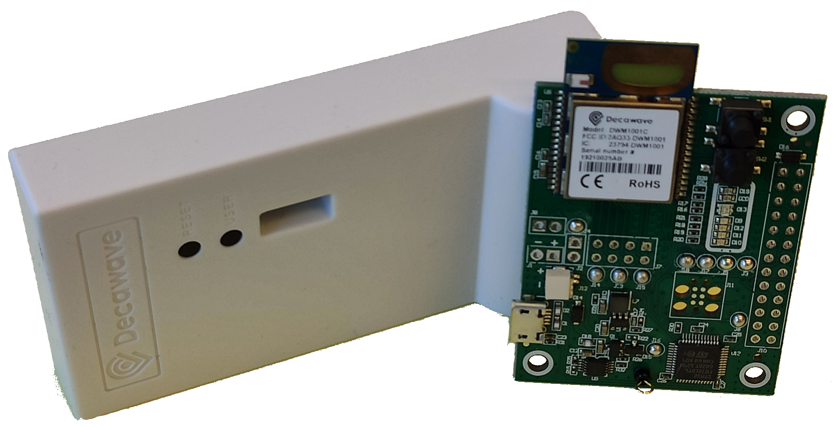
This autocalibration process has been implemented in C and the firmware for Decawave’s DWM1001 Development board, illustrated in Fig. 2, has been made publicly available in Github. Table 2 shows the difference in calibration accuracy between our firmware and Decawave’s DRTLS autopositioning system, the latter being a process that is triggered through the DRLTS mobile application. In our implementation, every time the autocalibration occurs, multiple measurements are taken and the average and standard deviation are shared with all other anchors to estimate each other’s positions. In Table 1, we show the latency when we take 5 or 50 measurements for each pair of anchors.
4 Experimental Results
In order to test the accuracy and usability of the autocalibration algorithm, we report two different types of results. First, we have measured the accuracy of UWB ranging with the DWM1001 transceiver, and the maximum error in which our autocalibration firmware incurs has been shown in Table 2. Second, we have utilized this data to study the localization accuracy in a simulation of a mobile deployment with multiple anchors and tags.
Regarding the measurements with the DWM1001 development board, we tested our autocalibration firmware to measure its latency and accuracy. The deployed network consisted of four anchors, one of which was placed in line of sight at different distances, ranging from 0.5 m to 22 m. The distances measured by the UWB modules during this experiment are depicted in Fig. 3. The results yielded from this experiment served to characterize the modules’ error.
In the simulation, we have also utilized 4 anchors. A minimum of three anchors is needed, but four anchors increase the system robustness in case one of the ranging measurements fail or the error is significant [15]. In addition, three tags were situated within the figure formed by the anchors to be localized. The movement of the anchors and the tags was generated following a constant direction with added random Gaussian noise. In every step, a random value in the interval was added to each anchor’s position, representing the error of the on-board position estimation utilized between calibrations. This range of values was chosen in order to have a significant error accumulated between calibrations and test the ability of the autocalibration process to bring the error down. The anchors’ calibration was performed every ten steps in the simulation. Both the calibration of the anchor positions and the positioning of the tags are done utilizing a least squares estimator, except for the initial positioning step before the movement starts.
The results of our simulation are shown in Fig. 4. Subfigures 4(a) and 4(b) show the error in anchors and tags positioning over 55 steps, respectively. It can be observed how calibration, performed every 10 steps, reduces significantly the anchors’ positional error. The number of steps shown in this figure is reduced for visualization purposes. We have carried out multiple simulations with hundreds of steps and observed the same behavior.
Finally, Fig. 5 shows the distribution of translation and rotation errors. The translation error was calculated for both anchors and tags and is illustrated in subfigure 5(a). The rotation error in subfigure 5(b) shows the error in the angle calculated between the x-axis and the line crossing the origin and Anchor 1. Note that Anchor 1 does not necessarily lie in the x-axis after the movement starts. In cases where the distance between these two anchors is enough this error is small. Therefore, the assumption that Anchor 1 defines the x-axis is only needed before the movement of the anchors starts.
5 Conclusion and Future Work
Motivated by the limitation on the applicability of UWB-based localization systems on dynamic scenarios, we have presented a mobile UWB-localization system with built-in autocalibration that can be deployed within a multi-robot system. The UWB anchors can be placed on mobile ground vehicles to support, for instance, the operation of UAVs and other robots in GNSS-denied environments. The key advantage of the proposed system is the periodic built-in self autocalibration of anchor positions. This allows for the localization error to stay within a certain tolerance even if the anchors are moving.
In future work, we will experiment with real multi-robot systems and provide a more exhaustive analysis of the usability of the proposed system in complex scenarios. We will also extend the calibration and localization approaches modelling the robots’ dynamics and their odometry algorithms.
References
- [1] First FCC. Report and order 02-48, 2002.
- [2] E. Karapistoli et al. An overview of the ieee 802.15. 4a standard. IEEE Communications Magazine, 48(1):47–53, 2010.
- [3] N. Macoir et al. Uwb localization with battery-powered wireless backbone for drone-based inventory management. Sensors, 19, 2019.
- [4] T. M. Nguyen et al. Integrated uwb-vision approach for autonomous docking of uavs in gps-denied environments. In ICRA. IEEE, 2019.
- [5] J. D. Taylor. Ultra-wideband radar technology. CRC press, 2018.
- [6] J. S. Furtado. Comparative analysis of optitrack motion capture systems. In Advances in Motion Sensing and Control for Robotic Applications. Springer, 2019.
- [7] L. Qingqing et al. Offloading Monocular Visual Odometry with Edge Computing: Optimizing Image Compression Ratios in Multi-Robot Systems. In The 5th ICSCC. IEEE, 2019.
- [8] V. K. Sarker et al. Offloading slam for indoor mobile robots with edge-fog-cloud computing. In 1st International Conference on Advances in Science, Engineering, Robotics Technology (ICASERT-2019), 2019.
- [9] K. Guo et al. Ultra-wideband and odometry-based cooperative relative localization with application to multi-uav formation control. IEEE transactions on cybernetics, 2019.
- [10] J. Peña Queralta et al. Communication-free and index-free distributed formation control algorithm for multi-robot systems. Procedia Computer Science, 2019. The 10th ANT Conference.
- [11] J. Peña Queralta et al. Distributed progressive formation control with one-way communication for multi-agent systems. In 2019 IEEE Symposium Series on Computational Intelligence, 2019.
- [12] J. Peña Queralta et al. Blockchain-powered collaboration in heterogeneous swarms of robots. Frontiers in Robotics and AI, 2020. Symposium on Blockchain for Robotic Systems, MIT Media Lab.
- [13] J. Peña Queralta et al. Collaborative mapping with ioe-based heterogeneous vehicles for enhanced situational awareness. In IEEE Sensors Applications Symposium (SAS), 2019.
- [14] F. Zafari et al. A survey of indoor localization systems and technologies. IEEE Communications Surveys & Tutorials, 21(3):2568–2599, 2019.
- [15] J. Peña Queralta et al. Uwb-based system for uav localization in gnss-denied environments: Characterization and dataset. arXiv preprint, 2020.
- [16] K. C. Cheok et al. Uwb tracking of mobile robots. In 21st Annual IEEE International Symposium on Personal, Indoor and Mobile Radio Communications, pages 2615–2620, 2010.
- [17] M. Hamer et al. Self-calibrating ultra-wideband network supporting multi-robot localization. IEEE Access, 6:22292–22304, 2018.
- [18] S. Güler et al. Real time onboard ultrawideband localization scheme for an autonomous two-robot system. In 2018 IEEE Conference on Control Technology and Applications (CCTA), pages 1151–1158, 2018.
- [19] B. Hepp, T. Nägeli, and O. Hilliges. Omni-directional person tracking on a flying robot using occlusion-robust ultra-wideband signals. In 2016 IEEE/RSJ International Conference on Intelligent Robots and Systems (IROS), pages 189–194, 2016.
- [20] S. Güler et al. Infrastructure-free multi-robot localization with ultrawideband sensors. In 2019 American Control Conference (ACC), pages 13–18, 2019.
- [21] P. Dawei et al. Design of indoor position system based on DWM1000 modules. 585:012067, aug 2019.
- [22] R. Mazraani et al. Experimental results of a combined tdoa/tof technique for uwb based localization systems. In ICC Workshops. IEEE, 2017.
- [23] Z. Wei et al. Joint positioning technique based on tof and tdoa. In 2018 IEEE International Instrumentation and Measurement Technology Conference (I2MTC), pages 1–6. IEEE, 2018.