Inter-orbital p- and d-wave pairings between and orbitals in Sr2RuO4
Weipeng Chen
National Laboratory of Solid State Microstructures And Department of Physics, Nanjing University, Nanjing 210093, China
Jin An
National Laboratory of Solid State Microstructures And Department of Physics, Nanjing University, Nanjing 210093, China
Collaborative Innovation Center of Advanced Microstructures, Nanjing University, Nanjing 210093, China
Abstract
We study the pairing symmetry of Sr2RuO4 through the group-theoretical approach. We emphasize the role of pairing interaction between the quasi-one-dimensional(Q1D) and quasi-two-dimensional(Q2D) orbitals. It is found that two degenerate inter-orbital time-reversal-invariant(TRI) p-wave pairings, one is spin-singlet and the other spin-triplet with out-of-plane -vector, could be the most promising candidates. Several important physical quantities are presented, including the near-nodal gap structure, the unchanged out-of-plane Knight shift, and no split transition under strain, which are consistent with the experiments. In addition, these p-wave pairings shed light on resolving the contradiction between the time-reversal breaking and reduced in-plane Knight shift measurements. As the system reaches the Van Hove singularity under applied strain, the pairing symmetry would become a d-wave pairing mainly consisting of inter-orbital components, which could be responsible for the strained 3 phase.
Introduction.—–Soon after the discovery of superconductivity() in Sr2RuO4, plenty of experiments have been made to catch its novel physics Ishida et al. (1998); Luke et al. (1998); Ishida et al. (2001); Laube et al. (2000); Suzuki et al. (2002); Nelson et al. (2004); Murakawa et al. (2004); Kidwingira et al. (2006); Xia et al. (2006); Jang et al. (2011). These experiments suggest the pairing order parameter(OP) be odd-parity, spin-triplet, and time-reversal-breaking(TRB), which leads to the widely accepted pairing state. However, this chiral order can’t resolve some apparently contradictory results Mackenzie and Maeno (2003); Maeno et al. (2011); Kallin (2012) such as: the nodal behaviors Graf and Balatsky (2000); NishiZaki et al. (2000); Bonalde et al. (2000); Ishida et al. (2000); Firmo et al. (2013); no split transition under applied symmetry-breaking fields Sigrist et al. (1987); Tsuchiizu et al. (2015); Mao et al. (2000); Yaguchi et al. (2002), and the missing chiral edge current Kirtley et al. (2007); Curran et al. (2011, 2014). It could also explain neither the Pauli limiting behavior nor the first-order transition Yonezawa et al. (2013); Kuhn et al. (2017). Recent studies on pressure effect provide a new insight Kittaka et al. (2010); Hicks et al. (2014); Burganov et al. (2016); Steppke et al. (2017); Barber et al. (2018). Tc increases slowly with small in-plane unaxial strain, indicating the absence of split transition, and then it reaches a sharp peak () at compression by 0.6%, accompanied by a strong enhancement of the z-axis upper critical fields . A promising proposal for this is that the OP of the 3K phase is even-parity, indicating an odd- to even-parity transition at an intermediate strain Steppke et al. (2017). The most interesting results come from the newest NMR measurements on superconducting Sr2RuO4, which obtained significant drops in the in-plane Knight shift for both unstrained and strained cases, ruling out the pairings with out-of-plane -vector Pustogow et al. (2019).
The puzzles above have triggered huge amount of theoretical works on the pairing mechanism Hasegawa et al. (2000); Raghu et al. (2010); Scaffidi et al. (2014); Huang et al. (2016); Zhang et al. (2017); Komendová and Black-Schaffer (2017); Huang and Yao (2018); Zhang et al. (2018); Wang et al. (2019), but the multi-orbital nature of the material makes this issue to be rather confused and unclear. There are three bands derived from the orbitals of Ru: , mainly from the Q1D and mainly from the Q2D . Most previous studies were focused on an active Q2D orbital Agterberg et al. (1997); Nomura and Yamada (2000); Wang et al. (2019), or the Q1D orbitals Raghu et al. (2010); Chung et al. (2012); Huang et al. (2016). We notice that pairings between the two kinds of orbitals have rarely been concerned, which could be owing to the general thought that the atomic spin-orbit couping(SOC) among the orbitals is too weak Yanase and Ogata (2003); Agterberg et al. (1997); Huang et al. (2016); Zhang et al. (2018). Recent theoretical and experimental results, however, support a much stronger SOC Veenstra et al. (2014); Zhang et al. (2016); Tamai et al. (2019), making this kind of pairings feasible. The possibility of such pairings in Sr2RuO4 has been discussed very recently Puetter and Kee (2012); Gingras et al. (2018); Huang et al. (2019); Kaba and Sénéchal (2019), but detailed investigations on them are still lacking.
In this letter, we highlight the role of the pairing interaction between the Q1D and Q2D orbitals and then make an analysis on the pairing symmetries in unstrained and strained Sr2RuO4. We find two degenerate inter-orbital TRI p-wave pairing states, one is spin-singlet and the other spin-triplet with out-of-plane -vector. Their physical quantities are consistent with several essential experimental facts: the vertical line nodes (near nodes) in the gap, the unchanged out-of-plane and reduced in-plane Knight shift, the Pauli limiting behavior, and the absence of split transition under uniaxial strain. These p-wave pairing states also shed light on explaining the observed time-reversal breaking. Furthermore, it is found that the strained Sr2RuO4 would undergo an odd-to-even OP transition as the system approaches the Van Hove singularity(VHS), suggesting that an inter-orbital-dominant d-wave pairing state could be the possible candidate of the strained 3K phase.
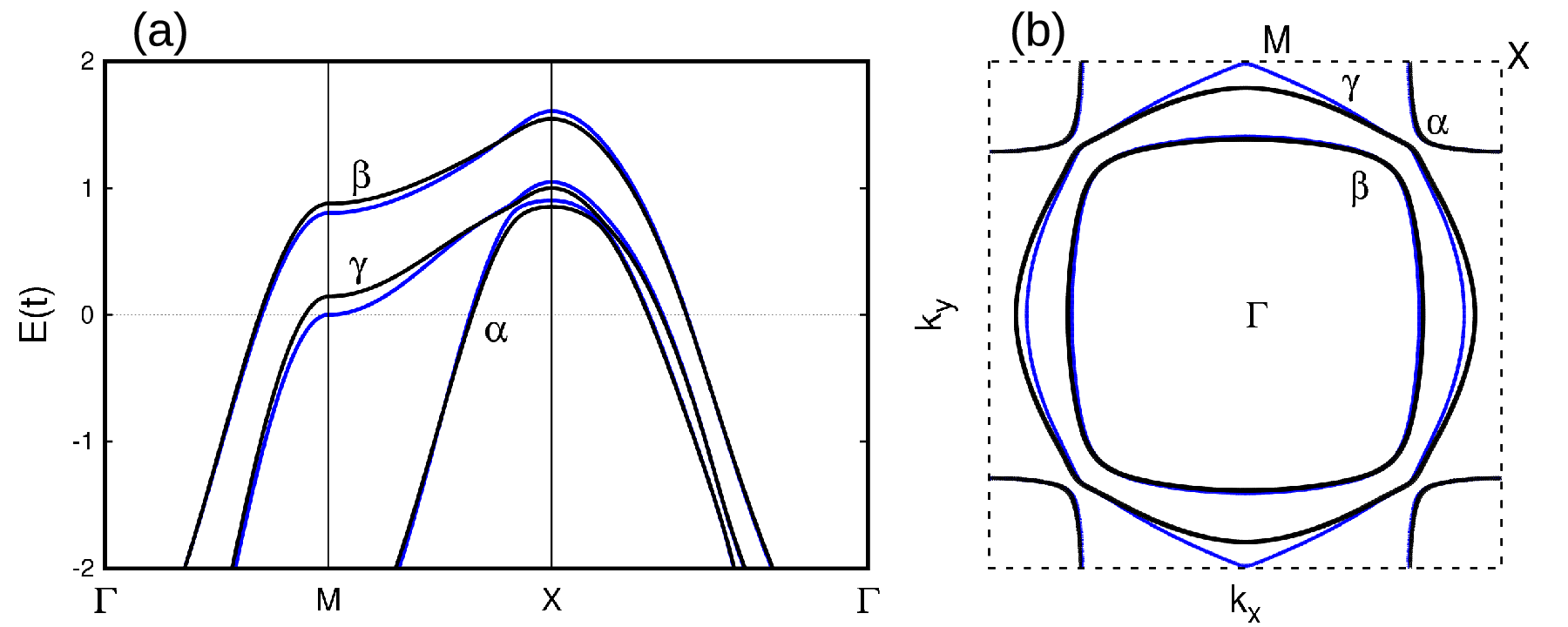
Figure 1:
(a) The fitted band structure. (b)2D FS of the normal Sr2RuO4. The black and blue lines correspond =0 and -0.75 %, respectively. The SOC strength is set to be .
Model and Method.—–
Based on the three orbitals, we construct a 2D tight-binding model to fit the Fermi surface(FS) revealed by the high-resolution photoemission Tamai et al. (2019); SM . The fitted energy band and FS of Sr2RuO4 are exhibited in Fig. 1. At zero strain, the 2D symmetry group of Sr2RuO4 could be or . Here we adopt the latter as in Ref. Zhang et al. (2014). We consider the -dependent pairings but ignore the on-site ones because of the deep gap minima observed in experiments Rastovski et al. (2013); Hassinger et al. (2017). For simplicity, only the nearest-neighbor(NN) pairings are involved in our paring symmetry analysis. Then the most favorable pairing state and its could be determined by solving the linearized gap equation
(1)
where is the normal states’ Matsubara Green functions, the gap matrix, the index combining the three orbitals and two spins. The pairing interaction could be expanded by the basis gap functions(BGFs) as follows
(2)
where represents the -th BGF for the irreducible representation(IR) , with being the corresponding coupling strength. The gap matrix could thus be written as a linear superposition of the BGFs and the coefficients are determined accordingly SM .
According to the crystalline symmetry Huang et al. (2016), is assumed to be independent of different IRs and only orbital dependent. It can be expressed by
(3)
where represents the intra(inter)-orbital pairing strength in the Q1D orbitals, between and , and that in , respectively. Because pairings within these two Q1D orbitals can never be dominant in our model, we simply set here, similar as employed in the work of Ref. Fukaya et al. (2018). For strained Sr2RuO4, should become anisotropic. While since the applied strains are small(denoted as ) Hicks et al. (2014); Steppke et al. (2017); Pustogow et al. (2019), the anisotropy is neglected so that Eq. (3) is assumed to be still valid in this situation.
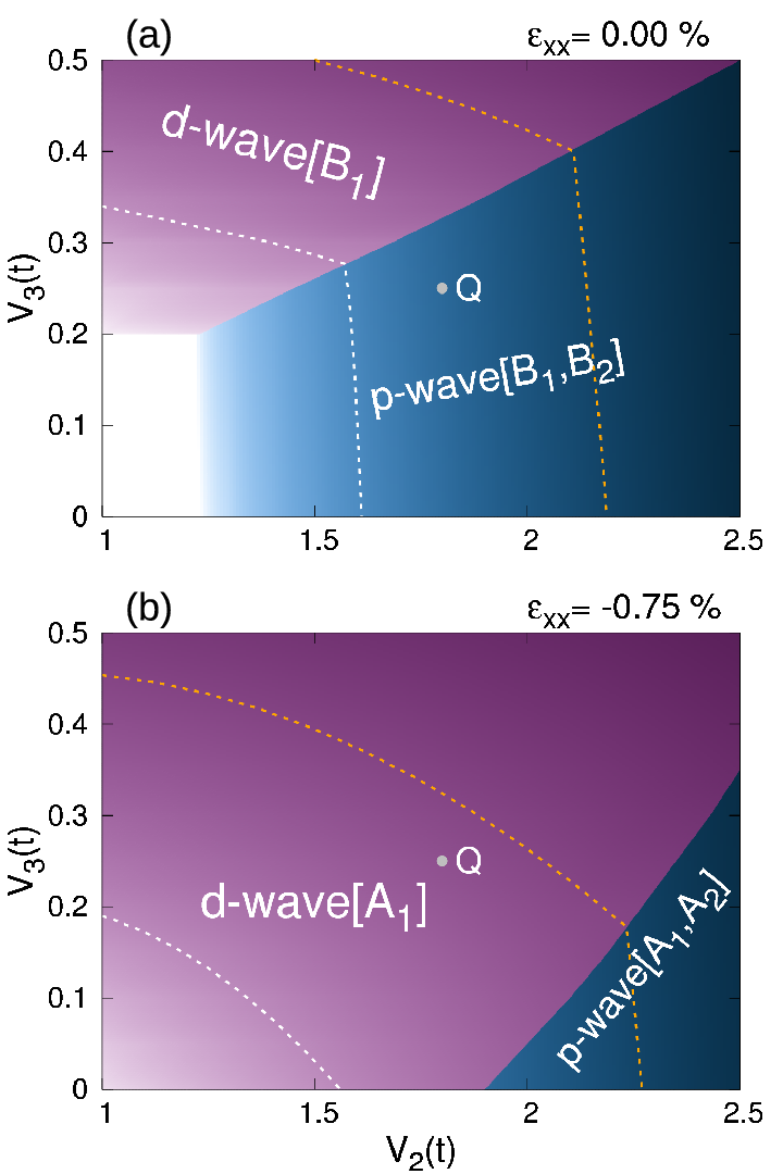
Figure 2:
Pairing phase diagrams with . (a)Unstrained Sr2RuO4. The upper regime denotes the d-wave pairing, while the lower one denotes two degenerate p-wave pairings belonging to and of . (b)Strained Sr2RuO4 with . Due to the reduced symmetry, the d-wave pairing belongs to , and the two p-wave pairings belong to and of . The white and orange dashed lines denote the regimes with and , respectively, assuming .
Phase diagram.—–Since the inter-orbital pairings between Q1D and Q2D orbitals are expected to play an important role, we assume to be the dominant coupling constant, much larger than the others. Our calculations demonstrate that the phase diagram is nearly unchanged as varies(), while it is very sensitive to the variation of . Therefore, in the following we are only focused on the parameter space with fixed . Fig. 2(a) shows the phase diagram of unstrained Sr2RuO4. There are two kinds of pairing states with distinct parities. One is a mixed TRI even-parity pairing state belonging to IR of , which is mainly composed of an inter-orbital d-wave pairing with an in-plane -vector , and an intra-orbital d-wave pairing. Although the latter is always a secondary component SM , it plays an essential role in stabilizing the phase. The other kind is the two degenerate TRI p-wave pairing states belonging to IR and . The leading component of the () p-wave order is an inter-orbital singlet(triplet) BGF, denoted by - [ - ]. Their degeneracy originates from a pseudo-spin-rotation symmetry of our Hamiltonian SM . Fig. 2(b) is the strained phase diagram at . Just like the unstrained case, only the d- and p-wave pairing states appear in the diagram. Under this unaxial strain, the point-group symmetry is reduced as and the corresponding IRs are transformed as , and Ramires and Sigrist (2019). Although the symmetry breaking causes additional admixtures among the BGFs, the leading components of the two orders in Fig. 2(a) are still dominant in Fig. 2(b) SM . The d-wave pairing now belongs to IR while the two degenerate p-wave pairings belong to and , respectively. For the p-wave case, our following related discussions will based on of (unstrained) and of (strained).
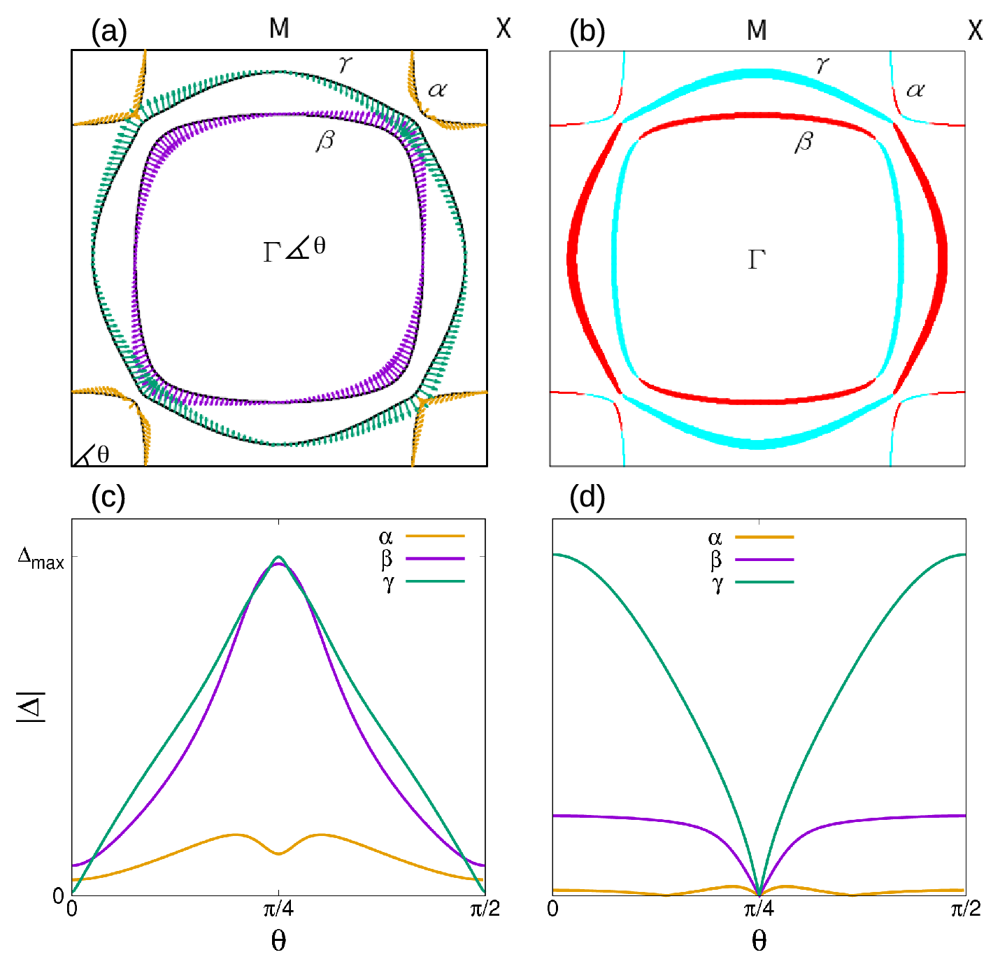
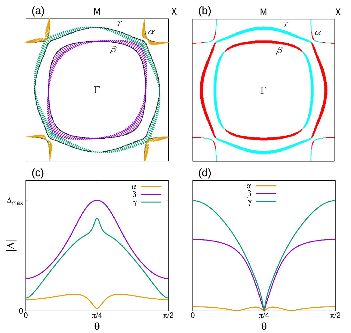
Figure 3:
Projected order parameters on the FS in the unstrained Sr2RuO4, with . (a) Projected -vectors of the p-wave pairing. (b) Projected of the d-wave pairing, where the red(cyan) line represents the gap sign () and the line width denotes the gap size. Their detailed gap-size dispersion on the FS are displayed in (c)(d), where is the azimuth angle around the FS pocket. The p-wave gaps have near nodes on all these three FS pockets at , while the d-wave cases have real nodes at .
Unstrained Sr2RuO4.—–Now we make gap projections of the two OPs without strain, and analyze their gap structures on the FS. It is found that, after the projection the p- and d-wave superconductivity remain TRI and emerge in the parallel and ‘anti-parallel’ pseudo-spin pairing channels, respectively SM . This allows us to describe the projected gap functions in a real -vector or form. The projected or pseudo--vectors on the three bands of the p-wave pairing are in-plane as depicted by Fig. 3(a). Gaps open mainly on and and have modulated helical p-wave forms, with their maxima(minima) living in the () directions. As shown in Fig. 3(c), all the three bands hold near nodes and the deepest ones give gaps about 1/60 of the maximum value.
Same as we did above, projected gaps of the d-wave pairing are shown in Fig. 3(b). Gap has the biggest magnitude and is much smaller, both of which take the form, while is rather tiny. All of them hold nodes along , as depicted by Fig. 3(d).
The anisotropic gaps revealed by the experiments support gap minima sitting on the sections Deguchi et al. (2004), indicating that the p-wave rather than the d-wave pairing could be a better candidate OP. To further confirm this one has to do more efforts on the physical properties for these two OPs. For the calculation details, one can refer to Ref. Wang et al. (2019). The temperature dependent gap sizes are obtained from the self-consistent gap equation Sigrist and Ueda (1991); SM .
Firstly, the specific heat divided by temperature are shown in Fig. 4(a). Both of the p- and d-wave pairings are nearly T-linear. Their specific heat jumps are 0.60 and 0.62, respectively, somewhat smaller than the experimental value 0.73 NishiZaki et al. (2000); Nomura and Yamada (2002); Deguchi et al. (2004).
At lower temperature(), however, the d-wave pairing shows a crossover behavior owing to the tiny gap on Agterberg et al. (1997), which is incompatible with the experiments mentioned above. The superfluid density are presented in Fig. 4(b). To compare our results with the experiment Bonalde et al. (2000), where the example has a , an estimated elastic scattering rate is taken into account Wang et al. (2019). These two OPs both display a quadratic behavior just as observed by the experiment below the temperature . Near , the d-wave pairing has a lower slope than the p-wave one, leading to an obvious downward concave character at about . Fig. 4(c) displays the spin-lattice relaxation rate. Comparing with the experiment in Ref. Ishida et al. (2000), where indicates a nodal structure, of our p-wave pairing shows a slight left shift, while that of the d-wave pairing yields a large deviation at the temperature . This is because the smallness of gap contributes a Korringa law , just like the normal state. It can be seen that the theoretical results of the p-wave pairing fits the experimental data better than the d-wave case, but still not good enough. We repeat these calculations using a larger SOC , with parameters modified to keep the nearly unchanged FS. Notice that the fit between our results and experiments for both the p- and d-wave pairings(the dashed blue and red lines in Fig. 4) are improved. However, the d-wave keeps far away from the experimental data. It can be seen that to fit these experimental data best an appropriate strong is required, which is coincident with our starting point.
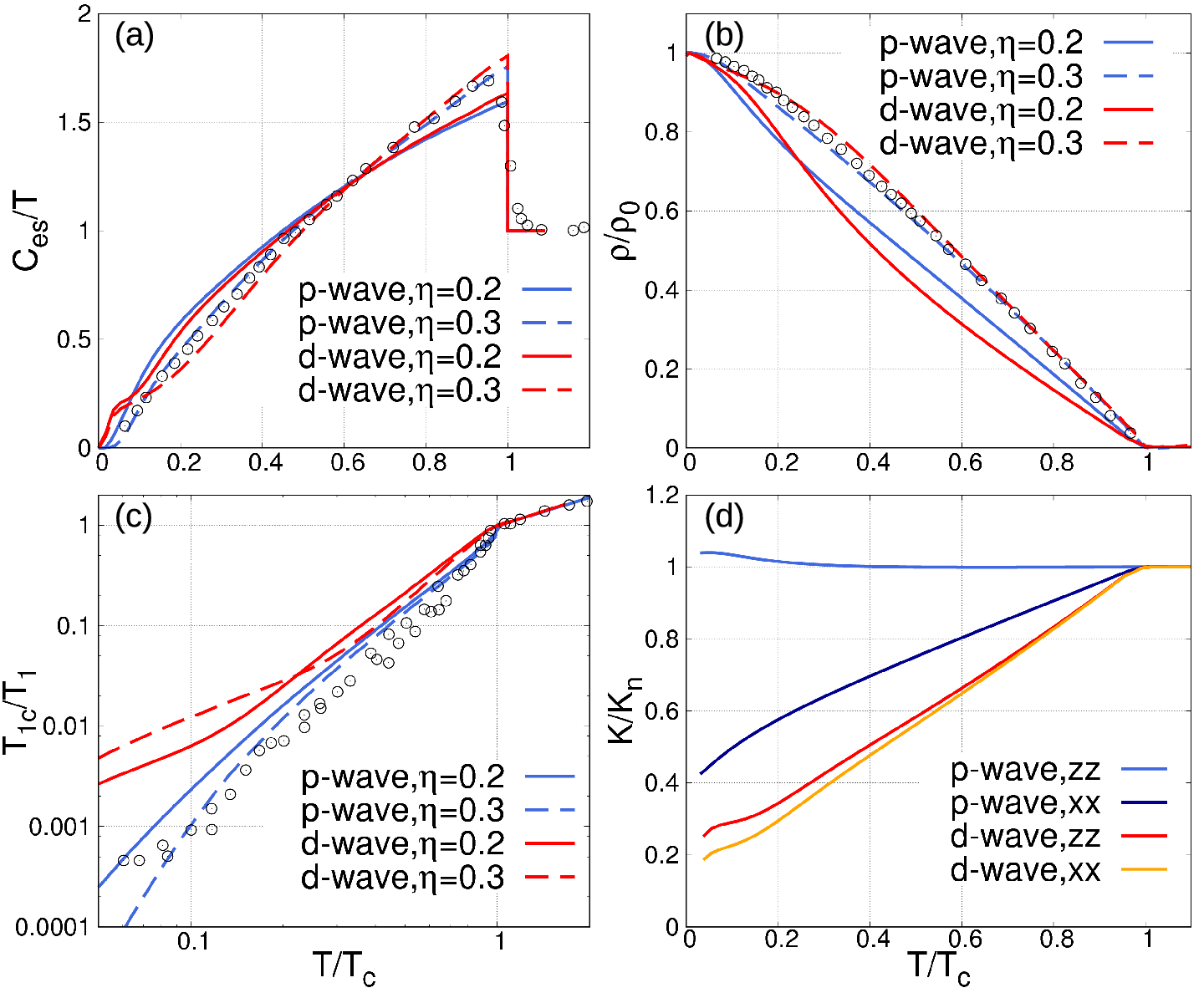
Figure 4:
Physical properties calculated for the two OPs in Fig. 2(a). (a) The electronic specific heat divided by temperature . (b) Superfluid density , (c) Spin-lattice relaxation rate . The blue(red) lines represent the p-wave(d-wave) case, in which the solid(dashed) one denotes the SOC strength . The circles are experimental data extracted from Ref. NishiZaki et al. (2000) for (a), Ref. Bonalde et al. (2000) for (b) and Ref. Ishida et al. (2000) for (c), respectively. (d) Normalized Knight shift . The blue(red) and dark-blue(orange) lines denote and of the p-wave(d-wave) pairing state, respectively.
Fig. 4(d) presents the normalized Knight shift , with being the normal value. In the d-wave case, and reduce as the temperature go through . This is similar to the behavior of a one-band d-wave model and qualitatively consistent with some theoretical results Yu et al. (2018); Røising et al. (2019).
In the p-wave case, shows nearly no change below but slightly increases near , while has a reduction about 58 % there. These characters are robust with respect to a small SOC variation and in agreement with the out-of-plane Knight shift experiments Ishida et al. (2001); Murakawa et al. (2004); Ishida et al. (2015) and very recent in-plane NMR measurements Pustogow et al. (2019); Ishida et al. (2019). We also apply the calculations on the p-wave pairing , and obtain exactly the same results. Notice that even these two degenerate p-wave pairings have different spin angular momentum: one is spin-singlet and the other spin-triplet, their projected -vectors are exactly the same: both in-plane and have a nodal structure(One can check this through the projection in SM ). Furthermore, our results are in agreement with the calculation of a helical pairing defined on the FS in Ref. Røising et al. (2019). This indicates that the Knight shift is strongly related to the projected -vectors. Given that a reduced Knight shift is always consistent with a Pauli limiting behavior, the projected -vectors could also be useful in describing the suppression of the in-plane upper critical field Rastovski et al. (2013); Amano et al. (2015); Ramires and Sigrist (2016); Zhang et al. (2018). In this sense, the projected gap functions could be treated as effective ones. It’s interesting to find that the original odd-parity OP, which is singlet or triplet with , will result in an unchanged , whereas the original even-parity OP, mainly triplet with in-plane -vector, gives sharply reduced Knight shift in any directions. These findings challenge the general concept of the relation between the pairing symmetry and Knight shift, indicating distinct magnetic-field responses of the inter-orbital pairings.
Strained Sr2RuO4.—–Now we turn to study the pairing OP of the strained Sr2RuO4. Stain drives the 1D IRs of to merge, which will induce additional mixing between the BGFs. For instance, the BGF will mix together with small amount of , resulting in a strained p-wave pairing which could be roughly denoted by with being different amplitudes of these two components. This demonstrates that there’s no splitting of the components under strain for our p-wave case, compatible with the observation Hicks et al. (2014); Steppke et al. (2017); Pustogow et al. (2019). The projected β, γV_iϵ_VT_c≃1.52 KT_c≃3.44 Kϵ_xx=ϵ_V3 K_2_4_2_4K_xxK_zz
Supplemental Materials
Table 1: The 6 independent BGFs and their relative amplitudes of a representative odd(even) pairing state of the unstrained Sr2RuO4, with the SOC strength . The bold gives amplitudes of the leading components.
Par
IR
Odd
-0.011
-0.054
-0.064
-0.044
-0.093
Par
IR
Even
0.003
-0.021
-0.030
0.184
Table 2: The 12 independent BGFs and their relative amplitudes of a representative odd(even) pairing state of the strained Sr2RuO4, with the SOC strength . The bold gives amplitudes of the leading components.
Par
IR
Odd
-0.017
0.017
0.004
-0.029
0.017
0.007
0.026
-0.020
0.089
0.047
-
Par
IR
Even
0.000
-0.022
0.113
0.003
-0.016
-0.015
0.019
-0.003
0.169
-0.011
-0.166
.1 Tight-binding model and Pairing Symmetry analysis
The FS sheets of Sr2RuO4 are derived from the orbitals , and of Ru, so we describe the 2D tight-binding Hamiltonian in a three-orbital representation as:
(4)
where the spinor is , with being electron annihilation operator and denoting the spin . The is given by
(5)
with
(6)
where denotes the SOC strength and the inter-orbital hopping term. represent the in-plane strain of Sr2RuO4 and are related by the Poisson’s ratio through , where . At zero strain, i.e., , parameters are set to fit the high-resolution photoemission
:. is chosen to make the first Lifshitz transition happen when . All the three energy bands and are two-fold degenerate due to the cooperation of space inversion and time-reversal symmetries.
The BdG Hamiltonian of the superconducting Sr2RuO4 is defined as
(7)
where is a matrix.
Because Sr2RuO4 is inversion-symmetric, pairings with different parities in momentum space could not mix together. In the basis of , can be divided into four subsectors as
(8)
If the even-parity are block off-diagonal(diagonal), then the odd-parity ones belonging to the same IR must be block diagonal(off-diagonal). To avoid confusion, we classify the gap functions by “even/odd” in momentum space rather than by “singlet/triplet” in spin space. As we will present, the former is not equivalent to the latter in a multiple-orbital pairing system, which is distinct from the one-band case. Because of the Fermi statistics, the superconducting gap matrix always obeys
(9)
Denote the pairing matrix between orbitals as
(10)
we have .
If the parity is even in momentum space, for instance, , then we have the orbital parity
(11)
else if the parity is odd, the following orbital parity must be satisfied:
(12)
We present all the nearest-neighbor pairing basis gap functions(BGFs) of the unstrained and strained Sr2RuO4 in Table 4 and Table 5, respectively. The BGFs may consist of pairings from different orbital channels and are shown in -vector or forms in these tables. In analogy with Eq. (10), the matrix can be defined, which gives accordingly and -vector . The only two nonzero elements of are: , , while those of can be given similarly. Function such as in these tables denotes the two pairings from different orbital channels mixing together symmetrically or antisymmetrically.
The total number of the -dependent BGFs of an -orbital system can be empirically expressed as , where is the number of the BGFs in the one-band case. Here for both and , so there are 72 BGFs in each table.
As the unaxial strain is applied, the point-group symmetry is reduced as and the corresponding IRs are transformed as , and . In the matrix form, each BGF is so normalized that:
(13)
where labels the BGF in IR and N is the number of unit cells in the system.
Table 1 and 2 show the relative amplitudes of each BGF for two representative pairing states without and under strain, respectively, with the normalization relation . The gap matrix can be expressed as a linear superposition of the BGFs in the IR :
(14)
where is the temperature dependent gap size. All in these tables are real, thus the obtained OPs here are TRI pairings£¬ indicating
(15)
with being the unitary factor relevant to the time-reversal operator. This relation can also be checked directly from the tables. We now make the following transformation of ,
(16)
where , with being the unitary matrix diagonalizing the normal-state Hamiltonian . Here denote the up, down pseudo-spin. Then the projected band gaps on the FS will be given by , where is the band index. The inter-band pairings are neglected due to the large energy separation between these bands. The corresponding pseudo--vector or on the band could also be defined through
(17)
Table 3: Same as Table 1 but the SOC strength is .
Par
IR
Odd
-0.026
-0.013
-0.022
-0.040
-
Par
IR
Even
0.00
-0.025
-0.032
0.099
We now prove that if the original pairing state is TRI, then the projected gaps on the FS will maintain this time-reversal symmetry.
In the basis of , can be reexpressed as with . The time-reversal invariance of the normal-state Hamiltonian can be written as , from which we get
(18)
For an arbitrary TRI pairing , the relation (15) leads to
In each equation we used twice of the Eq.(9), i.e., . These two equations guarantee the -vector or defined by Eq.(17) to be real, i.e., TRI.
.2 self-consistent gap equation
The temperature dependent gap function can be obtained from the mean-field self-consistent gap equation
where is the index combining the three orbitals and two spins, and the interaction terms could be expanded by all the BGFs as follows:
(23)
with being the pairing interaction for channel.
Multiplying by the two sides of equation (.2), then taking trace over indexes and making a sum over , we have
(24)
where is the temperature dependent gap amplitudes of each BGF defined through equation (14). Then the gap size and all these could be obtained by solving equation (24) through iteration.
.3 SOC strength
We also present the p- and d-wave gap structures in the unstrained Sr2RuO4 with a relatively larger SOC strength here, as shown in Fig. S5. To keep the FS nearly unchanged, the chemical potential and inter-orbital hopping strength are modified accordingly as . The corresponding relative amplitudes of each dominant BGF for a representative pairing state are given by Table 3. Compared to the case , although the ratios between BGFs of the p- or d-wave pairing vary a lot, the leading components are nearly the same, resulting in a similar gap structure. The p-wave pairing still holds minima along the direction on and , while it’s along on . It can be seen that this p-wave gap remains nearly nodal with an in-plane projected -vector. Gaps of the d-wave pairing are still d-wavelike and dominant on and .
Figure 5:
Projected OPs on the FS in the unstrained Sr2RuO4, with . (a) The projected -vectors of the p-wave pairing. (b) The projected of the d-wave pairing, where the red(cyan) line represents the gap sign () and the line width denotes the gap size. Their detailed gap-size dispersions on the FS are displayed in (c)(d).
Table 4: The 72 NN BGFs for the 2D point group . The 1st column shows the five
IRs. The symbol in the 2nd and 3rd columns denote the sign given by the basis functions under a fourfold rotation and mirror reflection, respectively. The symbol “” in 2D IR represents the two degenerate BGFs. The BGF can be described by a -vector or , which obeys for the even parity and for the odd parity. The red(blue) box denotes the dominant BGFs of the even(odd) pairing in Table 1.
Basis function
Even
Odd
+
+
+
+
Table 5: The 72 NN BGFs for the 2D point group . The 1st column shows the four IRs. The symbol in the 2nd and 3rd columns denote the sign given by the basis functions under a twofold rotation and mirror reflection, respectively. The orbitals involved in the pairing are displayed in the 4th column. The symbol “” in the 5th column represents two different BGFs(s- and d-wave) in the same IR. The BGF can be described by a -vector or , which obeys for the even parity and for the odd parity. The red(blue) box denotes the dominant BGFs of the even(odd) pairing in Table 2.
Orbital
Basis function
Even
Odd
+
+
()()()()()()
, ,
+
()()()()()()
, ,
()()()()()()
()()()()()()
.4 degeneracy of the order parameters
As we know, mixing of distinct BGFs could only occur within a definite IR .
However, our calculations reveal that the odd pairings belonging to and for are degenerate and thus could mix together. To understand it, one can define a pseudo-spin-rotation operator as
(25)
in the basis of three orbitals , where the spin of orbital is reversed. Since the pseudo-spin is conserved, the normal-state Hamiltonian is invariant under such a rotation about z axis. In the following, we take to demonstrate the degeneracy.
For the pairings with , , or , by making such a rotation, the gap function and -vector will transform as
(26)
indicating a z-axis rotation of the in-plane -vector. For instance, the BGF of IR for would be transformed to of IR . However, the ‘anti-parallel-spin’ pairings which is singlet, or triplet with out-of-plane -vector, would be invariant under the rotation.
On the other hand, when and or and , the same rotation will lead to
(27)
The parallel-spin pairings keep invariant under this rotation in this case. For the ‘anti-parallel-spin’ pairings, this transformation is highly nontrivial since it is between a singlet pairing and triplet pairing . This realization of transformation for the total spin of Cooper pairs from to is due to the fact that not spin but pseudo-spin is conserved. In this sense, the two components of p-wave pairing , are degenerate with those of , , respectively. For the same reason, the corresponding odd pairings of and for are degenerate too. Obviously, one can generalize this conclusion to the strained case, where the odd(even) pairings of are degenerate with that of for .
Despite the degeneracy between the odd pairings of different IRs discussed above, all the even pairings belonging to different 1D IRs for C4v should be non-degenerate since all these even pairing states are invariant under the rotation. Our detailed calculation of the linearized gap equation has also confirmed this.
References
Ishida et al. (1998)K. Ishida, H. Mukuda,
Y. Kitaoka, K. Asayama, Z. Mao, Y. Mori, and Y. Maeno, Nature 396, 658 (1998).
Luke et al. (1998)G. M. Luke, Y. Fudamoto,
K. Kojima, M. Larkin, J. Merrin, B. Nachumi, Y. Uemura, Y. Maeno, Z. Mao, Y. Mori, et al., Nature 394, 558 (1998).
Ishida et al. (2001)K. Ishida, H. Mukuda,
Y. Kitaoka, Z. Q. Mao, H. Fukazawa, and Y. Maeno, Phys.
Rev. B 63, 060507
(2001).
Bonalde et al. (2000)I. Bonalde, B. D. Yanoff,
M. B. Salamon, D. J. Van Harlingen, E. M. E. Chia, Z. Q. Mao, and Y. Maeno, Phys. Rev. Lett. 85, 4775 (2000).
Kirtley et al. (2007)J. R. Kirtley, C. Kallin,
C. W. Hicks, E.-A. Kim, Y. Liu, K. A. Moler, Y. Maeno, and K. D. Nelson, Phys. Rev. B 76, 014526 (2007).
Curran et al. (2011)P. J. Curran, V. V. Khotkevych, S. J. Bending, A. S. Gibbs,
S. L. Lee, and A. P. Mackenzie, Phys. Rev. B 84, 104507 (2011).
Curran et al. (2014)P. J. Curran, S. J. Bending,
W. M. Desoky, A. S. Gibbs, S. L. Lee, and A. P. Mackenzie, Phys.
Rev. B 89, 144504
(2014).
Kuhn et al. (2017)S. J. Kuhn, W. Morgenlander,
E. R. Louden, C. Rastovski, W. J. Gannon, H. Takatsu, D. C. Peets, Y. Maeno, C. D. Dewhurst, J. Gavilano, and M. R. Eskildsen, Phys. Rev. B 96, 174507 (2017).
Hicks et al. (2014)C. W. Hicks, D. O. Brodsky,
E. A. Yelland, A. S. Gibbs, J. A. Bruin, M. E. Barber, S. D. Edkins, K. Nishimura, S. Yonezawa, Y. Maeno, et al., Science 344, 283
(2014).
Burganov et al. (2016)B. Burganov, C. Adamo,
A. Mulder, M. Uchida, P. D. C. King, J. W. Harter, D. E. Shai, A. S. Gibbs, A. P. Mackenzie, R. Uecker, M. Bruetzam, M. R. Beasley, C. J. Fennie, D. G. Schlom, and K. M. Shen, Phys. Rev. Lett. 116, 197003 (2016).
Steppke et al. (2017)A. Steppke, L. Zhao,
M. E. Barber, T. Scaffidi, F. Jerzembeck, H. Rosner, A. S. Gibbs, Y. Maeno, S. H. Simon, A. P. Mackenzie, et al., Science 355, eaaf9398 (2017).
Pustogow et al. (2019)A. Pustogow, Y. Luo,
A. Chronister, Y.-S. Su, D. Sokolov, F. Jerzembeck, A. Mackenzie, C. Hicks, N. Kikugawa, S. Raghu, et al., Nature 574, 72
(2019).
Veenstra et al. (2014)C. N. Veenstra, Z.-H. Zhu,
M. Raichle, B. M. Ludbrook, A. Nicolaou, B. Slomski, G. Landolt, S. Kittaka, Y. Maeno, J. H. Dil, I. S. Elfimov, M. W. Haverkort, and A. Damascelli, Phys. Rev. Lett. 112, 127002 (2014).
Tamai et al. (2019)A. Tamai, M. Zingl,
E. Rozbicki, E. Cappelli, S. Riccò, A. de la Torre, S. McKeown Walker, F. Y. Bruno, P. D. C. King, W. Meevasana, M. Shi,
M. Radović, N. C. Plumb, A. S. Gibbs, A. P. Mackenzie, C. Berthod,
H. U. R. Strand, M. Kim, A. Georges, and F. Baumberger, Phys.
Rev. X 9, 021048
(2019).
(54)See Supplemental Material for details of the
tight-binding model, basis gap functions, gap projection, self-consistent gap
equation and analysis on the order parameter degeneracy.
Rastovski et al. (2013)C. Rastovski, C. D. Dewhurst, W. J. Gannon, D. C. Peets,
H. Takatsu, Y. Maeno, M. Ichioka, K. Machida, and M. R. Eskildsen, Phys. Rev. Lett. 111, 087003 (2013).
Hassinger et al. (2017)E. Hassinger, P. Bourgeois-Hope, H. Taniguchi, S. René de
Cotret, G. Grissonnanche, M. S. Anwar, Y. Maeno,
N. Doiron-Leyraud, and L. Taillefer, Phys. Rev. X 7, 011032 (2017).