Contract-based Methodology for Developing
Resilient Cyber-Infrastructure in the Industry 4.0 Era
Abstract
As the industrial cyber-infrastructure become increasingly important to realise the objectives of Industry 4.0, the consequence of disruption due to internal or external faults become increasingly severe. Thus there is a need for a resilient infrastructure. In this paper, we propose a contract-based methodology where components across layers of the cyber-infrastructure are associated with contracts and a light-weight resilience manager. This allows the system to detect faults (contract violation monitored using observers) and react (change contracts dynamically) effectively.
I Introduction
Industry 4.0 has the potential to radically improve the productivity of manufacturing systems. The next generation of smart factories can perform more efficiently, collectively and resiliently [1, 2, 3]. A resilient system has the ability to maintain and improve services even when challenged by failures and evolutionary changes. It indicates a system to be more flexible, more dynamic and less prescriptive than a traditional fault tolerant system [4].
Resiliency can be obtained using software or hardware based fault tolerance mechanisms. The latter solution demands physical redundancy such as replication of computational and communicational resources. For software based solutions, we find techniques such as replication of programs, checkpoints that act as restoration points and monitoring services that rely on timestamps [5] and fault trees, to detect faults. More recently, we see software adaptation techniques that switch between off-line generated code based on ontology [6] or application graphs [7], or dynamically create/modify code at runtime [2, 8].
Our cyber-infrastructure architecture follows the classical layered middle-ware with three different layers [3], see Fig. 1. The physical layer comprises physical components such as sensors, actuators, controllers and communication hardware. The platform layer embodies computational and communicational platforms such as operating systems and network managers. Finally, the application layer accommodates the software components which describe the behaviour of an application.
In [5] and [9], authors discuss an outline for a holistic approach for developing a resilient cyber-infrastructure that manages applications, devices, resources, deployment, security and time etc. However, [9] does not present any architecture details. In contrast, RIAPS [5] describes an architecture for developing a distributed resilient CPS. As an example, a resilient discovery service (DS) was explored; a failure of a publisher/subscriber pair is detected using heartbeat signals and timestamps. When a failure occurs, DS de-registers the pair from the list of registered services. A publisher/subscriber needs to re-register once they become active. The process of de-registering and re-registering is very time consuming and it also needs to be communicated with neighbouring nodes. In this scenario, the cause of the failure (e.g. intermittent fault in the physical layer) and the expected recovery time (e.g. 2 seconds or 2 hours) were not available to the DS manager residing in the platform layer. If the recovery time information was available to the DS manager, it can choose not to de-register a publisher/subscriber and avoid the unnecessary time consuming registration process across all neighbouring nodes. Thus, there is a need for communication across layers to improve resiliency.
I-A Problem statement
Existing resiliency techniques are inefficient due to two key limitations: (1) They do not consider cross-layer interactions of a cyber infrastructure [2, 6, 5, 7, 8]. (2) The techniques depend on a centralised decision-making component which collects information from other distributed components to detect faults [6, 7], except some which are tightly coupled to an industry standard [2, 8]. Both limitations (lack of cross-layer communication and centralised decision making) are not acceptable for Industry 4.0 where the cyber-infrastructure is heavily distributed and encourages attributes such as self-awareness where even the edge nodes of the network are expected to make decisions [1, 2]. This is unlike most existing pyramid-like infrastructure with predefined hierarchy of connections from sensors/actuators at the lowest levels and decision making software at the highest levels. Hence, there is a need for a new resilient methodology that allows for a more fine-grain distributed resilience management with cross-layer interactions and is aligned with the attributes of Industry 4.0.
I-B Proposed solution
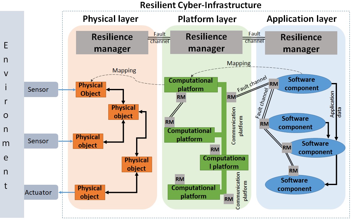
In this paper, we propose contract-based methodology where components across layers of the cyber-infrastructure are associated with contracts and a light-weight resilience manager, see Fig. 1. This allows the system to detect faults (contract violation detected using Timed or Hybrid Automata) and react (change contracts dynamically) effectively. When a component-level resilience manager is unable to provide any feasible solution to a fault, a layer-level resilience manager is informed. It has global-level understanding of the system and may find a feasible solution. We now discuss how the prosed methodology aligns with the attributes of Industry 4.0.
Self-reconfigurability: This refers to the ability for the individual node (or a component) to detect disturbances and apply corrective and pre-emptive measures. This attribute aligns with the core contribution of the proposed methodology. We use contracts to clearly define the functionality of a component. Any disturbances that violate the contracts are monitored using observers that run concurrently. As a recovery strategy a component switches between contracts (changing it’s behaviour) to contain faults, a step towards ensuring zero downtime production.
Self-optimisation: The availability of the resources in a cyber-infrastructure changes dynamically, detected using a discovery service [5]. The nodes are expected to self-optimise to improve performance. In order to maximise the performance, component manager tries to select the behaviour that locally maximises the use of available resources to yield the maximum Quality of Service (QoS). This may lead to a non-optimal solution, a limitation of our current work.
Peer-awareness: This refers to the ability to communicate with peers to collaboratively diagnose and respond to faults. In the proposed methodology, components communicate via fault communication channels to effectively deal with faults. For example when a producer that is publishing sensor data needs to be restarted, the consumer is informed that the producer is inactive and knows when it will be reactivated.
II Proposed contract-based resiliency
In this section, we describe a new methodology for developing distributed resilient architectures, called Contract-based Resiliency. It is motivated by component-based engineering which has been successfully used for large-scale system designs and the use of contract-based designs for explicitly pinpointing the responsibilities and assumptions of a component [10]. In our approach, we describe an application using a network of components and use contracts to capture the behaviour of the components. Finally, we detect failures (contract violation) and react (change contracts dynamically) to the disturbances, providing resiliency.
II-A Component architecture
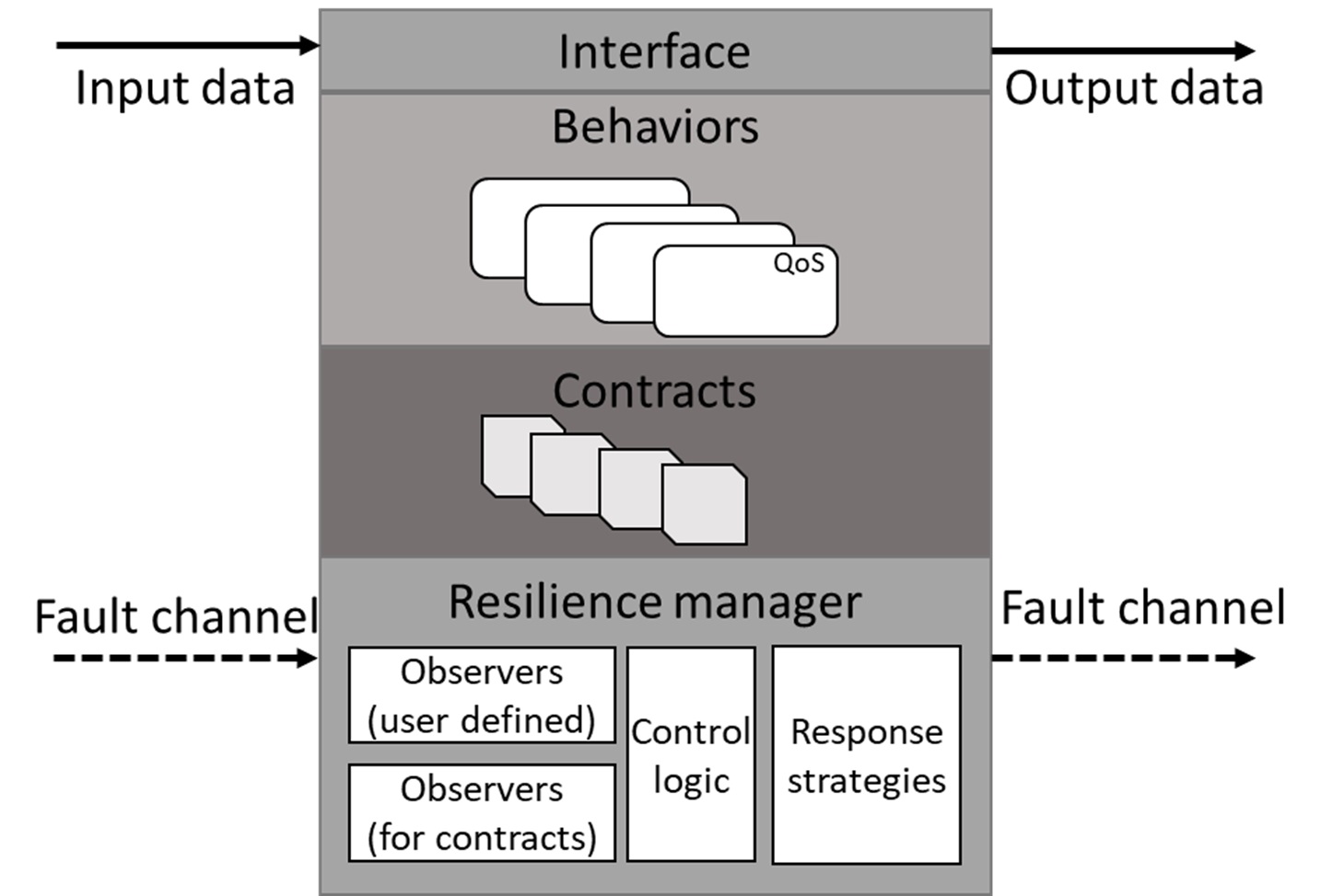
A component is an open system that receives inputs from the environment, executes a behaviour, and generates output to the environment. The environment could be the collection of other components or the physical world. An overview of a component is presented in Fig. 2.
-
•
Interface: It defines the Input/Output data channels of a component. Data is consumed through input interface, processed by the component, and output data is produced.
-
•
Behaviours: A component can be described using multiple behaviours. Each behaviour is associated with a QoS. At runtime, the resilience manager selects the behaviour of the component.
-
•
Contracts: A contract specifies assumptions on the behaviour of the environment, and guarantees about the behaviour of the component [10]. At runtime, the resilience manager can switch between contracts to react to the disturbances in the system.
-
•
Resilience manager: Detects faults (using Observers) and decides (control logic) the best course of action (response strategy). It also responds to the fault information from other components.
II-B Example application
Fig. 3 presents the running example, called Conveyor Belt Block Pick-up (CBBP). The application relies on the timing information from sensors S1 and S2 and then activate the robot at the right time to pick-up block from a moving conveyor belt.
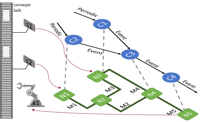
Application graph: The CBBP application is described as a set of connected components in the form of a graph, called application graph. The nodes of the graph are components and the edges represent communication between components. See the graph in Fig. 3 with components and . Component samples sensor () data periodically (). It applies different signal processing techniques (described using different component Behaviours, see Fig. 2) to extract the time () when the centre of a block is aligned with sensor . When the block is detected, the timing information () is sent to component . Similarly, component periodically samples sensor to compute and send the timing information () to component . Based on the received timing information, computes the time () when the robot needs to be activated and then sends it to component . Finally, the robot is activated to pick-up a block from the assembly line.
Mapping between application and platform layers: The platform layer comprises a set of computational platforms () and connecting communication platforms (). The mapping of the components in an application graph to computational platforms is shown in Fig. 3. E.g., component is mapped to computational platform . Assuming that has four possible behaviours (),
based on the mapping information we assume an execution time cost function is given. Furthermore, we assume the communication between components is handled by a network infrastructure. We assume a communication time cost function is given.
II-C Generating contracts from timing deadlines (off-line)
Using the speed of the conveyor belt we can compute the time taken for a block to travel from sensor (S1) to the actuator (robot), denoted as . We assume the decomposition of end-to-end timing constraints (e.g., 10 sec from S1 to robot) into deadlines for each component is given. For the CBBP example, we assume the end-to-end latency is decomposed as described by Eq. 1, where all terms are constants.
| (1) |
II-C1 Contracts to satisfy the timing constraint
Constant refers to the time taken for to read sensor and send the data to component . Based on existing notation [10], the first contract on , denoted by symbol is as follows.
Furthermore, we know that the sensors must be sampled periodically every . This requirement can be treated as a separate contract on , . In this case, both contacts can be composed 111Rules of composition is a part of the future work. They can be based on existing work [10]. .
II-C2 Contracts to satisfy the timing constraint
Constant refers to the time taken for to send the output data of to over a network and to send the data to .
Component has four behaviours with different execution times on , as described earlier. For each of the behaviours, we generate contracts. E.g., for behaviour the contract assumes nothing (represented using the symbol ) and guarantees execution of within .
We do not assume the communication delay to be a constant. At runtime, communication interface on and the network controller engage to create a contract that provides a time bound on the delivery of ’s data to .
Based on an expected time () for processing the received data on and sending it to , a single contract is created where it assumes nothing and guarantees the delivery within .
Finally, to monitor the timing constraint , observer executes on to monitor the timestamps on the data from to . Component was chosen since is mapped to . Note that if the observer was to execute on any other platform component such as , then timing information from need to be sent to . This unnecessarily increases the fault detection time of the architecture.
II-D Runtime reconfiguration
1. Application-level reconfiguration: The state of the application is described by an ordered set of contracts currently selected by the components to execute their behaviour. For the running example, the ordered set of components is . The initial state of the application can be . Any application-level reconfiguration is a transition from one application state to another. This state transition occurs when a fault is detected (violation of a contract) and a new contract is adopted by a software component.
2. Platform-level reconfiguration: As described earlier, the platform layer consists of computational and communicational platforms. Once again, the state of the platform can be described as an ordered set of contracts e.g., . Any platform-level reconfiguration is a transition from one platform state to another. E.g., due to high network traffic the contract needed to be re-negotiated to , representing a reconfiguration at platform level. Note, this may or may not lead to an application level reconfiguration.
III Fault-detection and Response
In the proposed resilience architecture, fault detection is tightly coupled with the contracts. A fault detection (violation of contracts monitored using observers) and response (change in contract by the resilience manger) will be managed efficiently. In the following, we discuss some of the faults experienced in distributed systems [11].
III-A Hanging processes
In this case, execution time of a process is longer than normal. For our example, component may take longer than expected. The time constraints are captured using the contract in Sec. II-C1. It states that the process must be completed within the duration of and the process must be executed every .
Fault detection technique: The contract is associated with an observer. The observer is implemented using timed automaton [12], see Figure 4.
Response to the fault: The observer failure is detected by the control logic of the resilience manager. As a response strategy, the component is restarted and the resilience manager of component is notified about the type of fault and the expected recovery time via the fault channel, see Fig. 2.
Based on the recovery time of a producer (e.g., ), the control logic of the consumer (e.g., ) may select different response strategies. For example, can reduce its execution time by selecting a different behaviour. In this case, based on the recovery time can be selected instead of . Of course, this reduces the quality of service. This response is achieved by switching the contracts at runtime from to , resulting in an application-level reconfiguration.
III-B Network outages
In this case, communication link has failed. For our example, consider the connection between and .
Fault detection technique: Using heartbeat signals component-level resilience managers of and periodically detect the status of the connection.
Response to the fault: Observers fail when the heartbeat signals are not received by the resilience managers of and . This triggers the control logic which can selects a response strategy such as switching from a wired to a wireless connection. Furthermore, if the component-level resilience managers were unable to re-establish the link, they would inform a layer-level resilience manager such as an SDN controller to find an alternative route.
IV Conclusions & Future work
We have presented a contract-based methodology for enabling resilient cyber-infrastructure for Industry 4.0. Applications are described as a set of modular components that are distributed over a network. Contracts are used for describing the component’s interaction with other components (and or across layers). Finally, the terms of the contract are monitored using observers. We detect failures (contract violation) and react (change contracts dynamically) to the disturbances, for providing resiliency.
In future, we plan to develop a multi-dimensional resilience metric to evaluate resilience with respect to different performance indicators such as security, safety, throughput, recovery time, etc. Furthermore, we plan to support parametrized contracts to automatically respond to faults across different components. E.g., if the robot is unable to meet the deadline to successfully pick-up blocks from the moving conveyor as a response the motor speed can be reduced (update contract w.r.t. conveyor speed). This idea is along our vision to support plug-n-produce which requires dynamic reconfiguration.
References
- [1] L. Jay, B. Behrad, and K. Hung-An, “A Cyber-Physical Systems architecture for Industry 4.0-based manufacturing systems,” Manufacturing Letters, vol. 3, pp. 18–23, Jan. 2015.
- [2] W. Dai, V. N. Dubinin, J. H. Christensen, V. Vyatkin, and X. Guan, “Toward Self-Manageable and Adaptive Industrial Cyber-Physical Systems With Knowledge-Driven Autonomic Service Management,” IEEE Transactions on Industrial Informatics, vol. 13, pp. 725–736, April 2017.
- [3] J. Sztipanovits and et al., “Toward a Science of Cyber-Physical System Integration,” Proceedings of the IEEE, vol. 100, pp. 29–44, Jan. 2012.
- [4] L. Strigini, “Fault Tolerance and Resilience: Meanings, Measures and Assessment,” in Resilience Assessment and Evaluation of Computing Systems (K. Wolter and et al., eds.), pp. 3–24, 2012.
- [5] E. Scott, I. Madari, A. Dubey, and G. Karsai, “RIAPS:Resilient Information Architecture Platform for Decentralized Smart Systems,” in International Symposium on Real-time Computing, IEEE, May 2017.
- [6] H. Oliver, I. Haris, S. Muhammad, and G. Radu, “A Self-Healing Framework for Building Resilient Cyber-Physical Systems,” in Proceedings of the Int. Symposium on Real-time Distributed Computing, IEEE, 2017.
- [7] M. G. Valls, I. R. Lopez, and L. F. Villar, “iLAND: An Enhanced Middleware for Real-Time Reconfiguration of Service Oriented Distributed Real-Time Systems,” IEEE Transactions on Industrial Informatics, vol. 9, pp. 228–236, Feb 2013.
- [8] W. Lepuschitz, A. Zoitl, M. Vallée, and M. Merdan, “Toward Self-Reconfiguration of Manufacturing Systems Using Automation Agents,” IEEE Transactions on Systems, Man, and Cybernetics, Part C (Applications and Reviews), vol. 41, pp. 52–69, Jan 2011.
- [9] G. Denker and et al., “Resilient dependable cyber-physical systems: a middleware perspective,” Journal of Internet Services and Applications, vol. 3, pp. 41–49, May 2012.
- [10] A. Benveniste and et al., “Contracts for Systems Design: Theory [Research Report] RR-8759,” tech. rep., 2015.
- [11] G. Kola, T. Kosar, and M. Livny, “Faults in Large Distributed Systems and What We Can Do About Them,” in Proc. of the Int. Euro-Par Conference on Parallel Processing, pp. 442–453, Springer-Verlag, 2005.
- [12] R. Alur and D. L. Dill, “A Theory of Timed Automata,” Theor. Comput. Sci., vol. 126, pp. 183–235, Apr. 1994.