Exact solutions for the wrinkle patterns of confined elastic shells
Abstract
Complex textured surfaces occur in nature and industry, from fingerprints to lithography-based micropatterns. Wrinkling by confinement to an incompatible substrate is an attractive way of generating reconfigurable patterned topographies, but controlling the often asymmetric and apparently stochastic wrinkles that result remains an elusive goal. Here, we describe a new approach to understanding the wrinkles of confined elastic shells, using a Lagrange multiplier in place of stress. Our theory reveals a simple set of geometric rules predicting the emergence and layout of orderly wrinkles, and explaining a surprisingly generic co-existence of ordered and disordered wrinkle domains. The results agree with numerous test cases across simulation and experiment and represent an elementary geometric toolkit for designing complex wrinkle patterns.
Introduction. Dried fruits wrinkle for the same reason that leaves and flowers do — mechanical instabilities arising from a mismatch in lengths Sharon et al. (2002); Cerda and Mahadevan (2003); Audoly and Pomeau (2010); Shyer et al. (2013); Gemmer et al. (2016); Xu et al. (2020); Fei et al. (2020). A similar mismatch manifests when a thin elastic shell adheres to a substrate of a different shape Hure et al. (2012); King et al. (2012); Paulsen (2019); Vella (2019); Timounay et al. (2021). Can such incompatibilities be used to design and control complex wrinkled surfaces at will? Wrinkles have been in the limelight for their theoretical importance in understanding geometric nonlinearities in elasticity Breid and Crosby (2013); Stoop et al. (2015); Reis (2015); Aharoni et al. (2017); Bella and Kohn (2017); Zhang et al. (2019); Davidovitch et al. (2019); Tovkach et al. (2020), and also for their practical significance in emerging engineering applications such as lithography-free micropatterning Pretzl et al. (2008); Yang et al. (2010); Chen and Yang (2012); Li et al. (2017). Yet, despite decades of study, a general predictive theory of confinement-induced wrinkling remains elusive. Such a theory would enable the creation of targeted yet reconfigurable wrinkle patterns, and could identify the broadest possible class of wrinkle morphologies that can be obtained through geometrically-incompatible confinement.
Predicting the wrinkling of confined elastic shells is a difficult problem of nonlinear mechanics. Basic theoretical issues stem from a lack of applied tensile forces that would act to organize the response. In problems dominated by tension, the guiding principle is known as tension field theory Wagner (1929); Pipkin (1986); Steigmann (1990), and solving it is the first step in the far-from-threshold expansion that has explained many tension-driven patterns Davidovitch et al. (2011); King et al. (2012); Bella and Kohn (2014); Hohlfeld and Davidovitch (2015); Vella et al. (2015); Taffetani and Vella (2017). Organized wrinkles nevertheless manifest in confined shells subject to weak or even zero tensile loads Hure et al. (2012); Aharoni et al. (2017), raising the question of what sets their features. Though theoretical methods beyond tension field theory have been devised Davidovitch et al. (2019), their use requires advance knowledge of the wrinkled topography. Here, we show using theory, experiment, and simulation that the wrinkles of confined shells are in fact predicted by a compact set of simple, geometric rules. We derive our rules using a stress-like Lagrange multiplier, that arises from a Maximum Coverage Problem for the macroscopic displacement of the shell (Eq. (3)).
These rules imply a string of predictions about the nature of confinement-driven wrinkling, which we confirm using experiments and simulations over a broad range of parameters and shell shapes. As we prove, a typical shell exhibits finitely many ordered wrinkle domains where the wrinkle layout is robust; the theory also anticipates the existence of disordered wrinkle domains, whose local features behave stochastically but whose location is well-defined (Fig. 1a,b). Second, the arrangement of these domains, and their division into ordered versus disordered, is fundamentally tied to the shell’s medial axis, a distinguished locus of points from geometry. Third, although the wrinkle amplitude depends on the details of the shell’s natural Gaussian curvature, within an ordered domain the wrinkle topography actually depends only on its sign. Finally, and perhaps most surprisingly, the wrinkle domains of oppositely curved shells are reciprocally related, so that the response of a given shell can be deduced from another. Although our study focuses on the model problem of a shallow shell confined to a plane, we imagine a similar approach can be taken to understand confinement-driven patterns more generally, including ones arising from differential growth or in response to external stimuli Amar and Jia (2013); Reis (2015); van Rees et al. (2017). We turn to introduce the setup of our study and to state our rules.
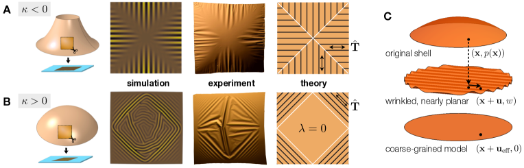
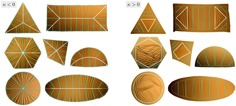
Confined shells. A prototypical setup for confinement-driven wrinkling is shown in Fig. 1a,b, where square domains are cut out from a thin saddle shell or spherical cap, and are confined to an initially planar liquid bath. By Gauss’s Theorema Egregium, no length-preserving map exists from a curved surface to the plane. Here, this geometric incompatibility manifests as a mechanical instability producing a wrinkle pattern. Figure 3 shows similar wrinkles obtained by altering the cutout shape from a square to a triangle, rectangle, ellipse, or some other shape altogether. The layout of the resulting patterns depends strongly on the chosen cutout shape, as well as on the sign of the shell’s initial Gaussian curvature , which is negative for saddle cutouts and positive for spherical ones. Complicating things further, the typical spherical shell exhibits a mixed “ordered–disordered” response: in disordered regions such as the central diamonds in Fig. 1b, the response is sensitive to perturbations and changes between trials; in ordered regions, the wrinkles are robust and repeatable.
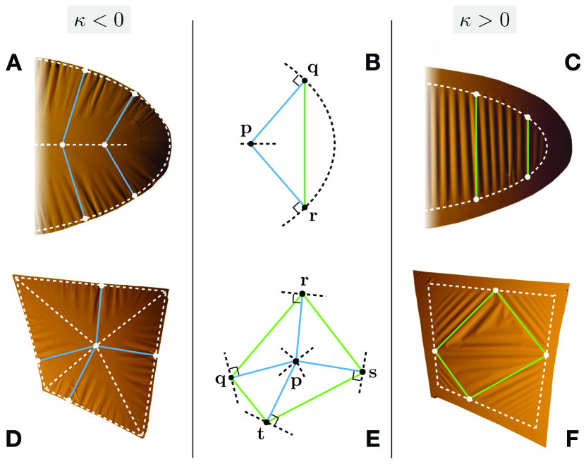
To decipher this zoo of patterns, look first at the wrinkles of the saddle cutouts in Figs. 1-3 (). Apparently, their wrinkles fall along paths of quickest exit from the cut out shape. Such paths are line segments that meet the boundary perpendicularly, and meet each other at the medial axis or skeleton of the shell — the locus of points equidistant by closest approach to multiple boundary points, in white. Now look at the spherical cutouts (). Their wrinkles are also set by the medial axis, although this fact is not immediately clear. The key is Fig. 2, which reveals that the wrinkles of saddle and spherical shells come in reciprocal pairs. Most points on the medial axis have exactly two closest boundary points, called and in panel (b). While saddle cutouts wrinkle along the segments and , spherical cutouts wrinkle along the segment . Taken together, the ordered wrinkles of saddle and spherical shells form the legs of a special family of isosceles triangles whose layout is determined by the medial axis as shown.
Notably, the legs of these isosceles triangles do not always cover the entire shell: there can exist “leftover” regions linked to exceptional points on the medial axis with three or more closest boundary points. Figure 2(e) shows one such and its four closest boundary points , , , and . While , , , and are along the ordered wrinkles of the saddle cutout, the polygon supports disorder for its spherical twin. In general, the convex hull of three or more closest boundary points can support disorder in a spherical cutout. The possibility of infinitely many closest boundary points occurs for a spherical disc: it is totally disordered in our simulations and experiments, save for a small flattened rim Timounay et al. (2021).
These simple rules successfully capture wrinkle patterns across experiments and several hundred more simulations. In the experiment, polystyrene films (Young’s modulus GPa, Poisson’s ratio ) of thickness nm are spin-coated on curved glass substrates. The spherical or saddle shape of the substrate imparts a finite rest curvature on the shell, with principal radii of curvature ranging from to mm. Cutouts of width mm are released onto a flat water bath with surface tension N/m and gravitational stiffness . The experiments reside in the limit of weak tension , moderately stiff substrate , and small bending stiffness where and are the stretching and bending moduli. Being shallow yet much larger than the characteristic substrate-dominated wrinkle wavelength, , the cutouts adopt approximately planar shapes and wrinkle as they float on the water bath, as shown in Figs. 1-3.
To probe the role of surface tension in setting the patterns, we perform ABAQUS simulations of shells on a liquid substrate in a similar parameter regime, but with the surface tension set to zero so that no forces are applied at the lateral shell boundary. The result is a “softly stamped” version of the well-known example of a plate pressed into a hard spherical mold Hure et al. (2012); Davidovitch et al. (2019). Similar patterns arise in the simulation and the experiment, with the layout of the ordered domains and the location of the disordered domains being the same (Fig. 1a,b). The conclusion, which should be compared against the paradigm of tension as an organizing force determining wrinkle patterns Pipkin (1986); Steigmann (1990), is that well-defined and spatially-complex patterns persist even without applied tensile forces. Simulations of shells with non-constant initial Gaussian curvatures reveal an even more curious fact: so long as the initial Gaussian curvature of a shell is of one sign — either positive or negative everywhere — the patterns are the same as for shells with approximately constant curvature (compare Figs. 3 and 4).
Minimizing energy by maximizing coverage. We turn to explain these remarkably robust features of confinement-driven wrinkling, and to derive our simple rules. We do so by analyzing a novel coarse-grained model for incompatibly confined shallow shells from Ref. Tobasco (2021), which we summarize now. Consider the setup in Fig. 1c, where a material point in the initial shell displaces to on the bath. The reference point is in the shell’s initial planform , e.g., a square in Fig. 1a,b. The displacements and are respectively parallel and perpendicular to the initial bath. Patterns manifest through minimization of the system energy, , where is the energy of bending and stretching the shell, and is the gravitational potential energy of the bath plus its liquid surface energy (the latter is set to zero in the simulations) Audoly and Pomeau (2010); Ciarlet (1997).

Energy minimizations of this type are usually solved using tension field theory Pipkin (1986); Steigmann (1990), which involves an expansion about a uniaxially or biaxially tensile effective displacement . This effective state is obtained by coarse-graining away the wrinkles from the shell’s physical displacement , in a limit where the wrinkle wavelength and amplitude go to zero (Fig. 1c). The typical explanation is that the direction of the wrinkles is set by tensile boundary loads, which stabilize their peaks and troughs. Yet, our patterns occur in confined shells subject to small or even zero boundary loads, suggesting an alternate expansion about a uniaxially or biaxially compressive state — one that is tension-free. To motivate this further, note that in such a situation, one may expect the stretching energy of the shell to be subdominant to its bending and substrate energies Davidovitch et al. (2019). Under a simplifying hypothesis guaranteeing this hierarchy, Ref. Tobasco (2021) obtained an expansion of the system energy about a general tension-free state. As obtained, this expansion is outside the parameter range of the experiments and simulations. Nevertheless, for each the energy was found to be proportional to with at leading order, up to a constant not depending on the effective state.
To bring this into a more useful form, note the strain , tends to zero in the expansion, so that the shell’s total area is asymptotically conserved:
| (1) |
Taking gives the following expression for the leading order energy of a confined shallow shell Tobasco (2021):
| (2) |
where is the outwards pointing unit normal to the boundary, . This way of writing the energy emphasizes the role of the difference between the shell’s initial area, , and the area covered by its infinitesimally wrinkled, perfectly planar limit, . This difference accounts for the area that is “lost” asymptotically to wrinkles. It sets the energy of confinement per Eq. (2). Notably, this energy is not proportional to the stretching modulus as significant tension is not involved. Indeed, (2) was found to hold even in situations lacking boundary loads () — a stark difference from tension field theory. And as we will show, the analysis of Eq. (2) leads to the patterns observed in our experiments and simulations, raising the question of whether it can be justified in a wider parameter range.
Optimizing the result of Eq. (2) determines the effective displacement of the shell. To help visualize this, imagine first projecting the shell directly into the plane, such that it is in a state of total compression. While this compression can be relieved by wrinkling, it can also be reduced by lateral displacements within the plane. These displacements take advantage of the liquid nature of the bath, which allows the shell to “get out of its own way”. Their typical magnitude is , making them much larger than the wrinkles, whose lateral oscillations are . The bulk lateral displacements are called in the coarse-grained theory and are selected to minimize the cost of their accompanying wrinkles, captured by .
Importantly, this minimization is done under the constraint that is tension-free, to prevent the shell from stretching at a higher energy cost. To enforce it, we use the effective strain gotten by setting and into the previous formula for the strain of a shallow shell. While the physical strain tends to zero, the effective strain is non-zero due to wrinkling. Its eigenvalues are constrained to be non-positive, a situation we denote by . As in tension field theory, a strictly negative eigenvalue indicates a length lost to wrinkles in the limit; a zero eigenvalue means that length is preserved. Thus, we arrive at the Maximum Coverage Problem from Tobasco (2021):
| (3) |
By minimizing the area lost to infinitesimal wrinkles, the coarse-grained shell covers a maximal area in the plane. Using this attractive geometric variational principle, we shall deduce the phenomenology of wrinkle domains.
The locking stress Lagrange multiplier. To uncover the patterns predicted by the Maximum Coverage Problem, we now introduce a notion of “effective stress” to pair with the effective strain. Recognizing the nonholonomic nature of the constraint , we replace it with a symmetric matrix-valued Lagrange multiplier field we call the locking stress (see the Discussion for the nomenclature). We require that , meaning its eigenvalues are non-negative. We define the Lagrangian
| (4) |
for all and , and seek a saddle point. Enforcing stationarity of , we find that in the shell and at its boundary . As discussed in the Methods, a relaxation of the boundary conditions ensures existence of a saddle point: we enforce them from the outside of the shell, but not necessarily from its inside. There, we also derive the orthogonality relation
| (5) |
relating the locking stress to the effective strain. At this point, we have everything we need to solve for the wrinkle domains. Indeed, while is not the true stress in the shell (neither is the true strain), knowledge of it reveals constraints on the patterns to the point that it is an order parameter for wrinkle domains.
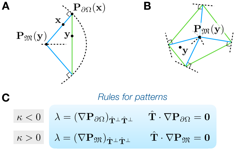
To explain this last remark further, note first that cannot vanish where the initial Gaussian curvature of the shell is non-zero. Due to the orthogonality in (5),
| (6) |
for some scalar and unit vector fields and which contain information about the patterns. In particular, by (5) and (6), these quantities obey
| (7) |
In regions where the -component of must vanish, indicating an ordered domain with wrinkle peaks and troughs along . Conversely, where the wrinkle direction is unconstrained, permitting a disordered response. The type and layout of a given shell’s wrinkle domains are predicted by the locking stress.
Remarkably, it is possible to find the locking stress of a shell without first determining its effective strain, an observation that leads to a complete derivation of our simple rules. Eliminating from the Lagrangian in (4) by minimization yields a separate, “dual” variational principle for (Methods Eq. (10)). We solve it exactly in the Supplementary Information, using convex Airy potentials and an inspired application of the Legendre transform. The resulting solution formulas determine and by one of two basic geometric operations, shown in Fig. 5. These formulas apply whenever the shell has no holes and if its initial Gaussian curvature is of one sign. They are the basis of our simple rules (compare Figs. 2 and 5). For instance, the fact that if explains why the wrinkles of negatively curved shells lie along directions of quickest exit to the shell boundary. The remaining rules are derived in the SI.
Coming back to our experiments and simulations, we now derive their patterns. In Fig. 3, cyan lines are drawn along the solved-for in the predicted ordered regions (where ). Each negatively curved shell is found to be completely ordered. Regions consistent with disorder (where ) exist for generic positively curved shells, and are shown as polygons bordered in white. The wrinkle domains are set by the shells’ medial axes following our simple rules.

Discussion. Given the success of our rules in capturing the wrinkles of confined shells, it is natural to consider other instances of reciprocity as well as graphical methods in mechanics more broadly. A well-known method is due to Maxwell Maxwell (1864) and also Taylor, whose reciprocal diagrams of forces and frames encode an elegant test of equilibrium for planar structures Timoshenko (1953). Our relations connecting the wrinkles of positively and negatively curved shells reveal a new class of reciprocal rules governing incompatible confinement. We wonder how far they generalize. Examples of shells for which we presently lack rules are in Fig. 6a,b. Finally, Fig. 6c highlights the fact that ordered wrinkles sometimes occur in regions the theory predicts to be consistent with disorder. Empirically, the presence of order versus disorder looks to depend on the finite wrinkle wavelength. Related to this is the question of the greatest parameter regime in which the Maximum Coverage Problem in Eq. (3) can be derived. Though it predicts the patterns in our simulations and experiments well, it has yet to be established for the parameter range they explore. We imagine a full proof of Eq. (3) will come from combining the “inverted tension field theory” of Davidovitch et al. (2019) with the ansatz-free arguments in Tobasco (2021).
We have shown how to predict the wrinkles of confined shallow shells, using a compact set of geometric rules gotten by solving the coarse-grained theory of Tobasco (2021). Our results point towards a general, diagrammatic method for benchmarking elastic patterns, which could prove useful for their rapid design. We highlight a promising connection with the theory of ideal locking materials — bulk materials whose microstructures facilitate extension with negligible elastic stress below a threshold strain Prager (1957). This limit is apparently approached in biology, by the mesentery membrane of rabbits Fung (1967); Prager (1969) and the capture silk of some spiders, the latter of which has recently inspired ultrastretchable wicked membranes Elettro et al. (2016); Grandgeorge et al. (2018). We view the wrinkles of confined shells as an emergent-yet-sacrificial microstructure enabling shape change. This underlies our terming the Lagrange multiplier from our solutions as the locking stress. It plays the role of an order parameter for predicting wrinkle domains. The extension of our rules beyond shallow shells and to patterns involving elements others than wrinkles, including crumples King et al. (2012); Timounay et al. (2020) and folds Pocivavsek et al. (2008); Brau et al. (2013); Paulsen et al. (2017), remains to be seen.
Methods.
Experiment. Dilute solutions of polystyrene ( kDa, kDa, Polymer Source) in toluene (99.9%, Fisher Scientific) are spin-coated onto glass substrates of various positive and negative Gaussian curvatures. The positively curved substrates are spherical optical lenses (Thorlabs, Inc.). Negatively curved shells were formed on a single negative-curvature substrate that is less controlled by comparison; its principal radii of curvature were measured from side-view images and are reported in Supplementary Table S1.
Film thickness is varied by changing the polymer concentration and spinning speed. Different shapes are cut out using a metal scribe. After preparing the glass substrates with a thin layer of poly(acrylic acid), the films are released by dissolving this sacrificial layer in water. The films are finally transferred to a pure water–air interface. Following the experiments, each film is captured and its thickness is measured using a white-light interferometer (Filmetrics F3).
The shells are shallow with and have non-dimensional bending modulus in the range . The non-dimensional substrate stiffness and non-dimensional surface tension obey and . Additionally, , , and . These ranges are in line with all but one of the assumptions used in Ref. Tobasco (2021) to derive Eq. (2) (they do not obey ). Specific parameters for the experiments shown in the main text are in Supplementary Tables S1-S2.
Simulation. Shells bonded to a planar liquid substrate without surface tension are simulated in the finite element package ABAQUS/Explicit. Four-node thin shell elements with reduced integration (element type S4R) are used. The confining force is specified as a non-uniform distributed pressure load over the surface of the shell, via a VDLOAD subroutine. Otherwise, free boundary conditions are used. Comparative non-linear geometric finite element analysis using linearly elastic and neo-Hookean hyperelastic materials show the results are largely independent of the model. Color-coding in the images corresponds to vertical deflections from the plane.
In the same non-dimensional groups as before, the simulations have , , , and . Additionally, and . As with the experiments, these ranges are in line with all but one of the assumptions of Ref. Tobasco (2021) (they do not obey ). Specific parameters for the simulations shown in the main text are in Supplementary Table S3.
Theory. Here we connect the Lagrangian in Eq. (4) of the main text to our coarse-grained fields. We assert the existence of a saddle point satisfying
| (8) |
for all and with Tobasco (2021). The key linking saddle points to the Maximum Coverage Problem (Eq. (3)) is that such points yield its solutions. To study saddles in detail, we evaluate the “min-max” and “max-min” procedures and .
First, consider the min-max: we claim that
| (9) |
where on the right the tension-free constraint is used. Eq. (9) states that solving the Maximum Coverage Problem is equivalent to finding the min-max of , and explains why its saddle points contain our effective displacements. To prove it, note the inner maximization over enforces the tension-free constraint: if a component of is positive, then by sending the same component of to infinity we get ; conversely, if is tension-free then and . Evidently, minimizing the maximum prefers tension-free states. It follows that saddle points achieve or, equivalently, that . Since the integrand is non-positive it must vanish, proving the orthogonality relation (5).
Next, consider the max-min: a computation in the SI using the divergence theorem gives
| (10) |
where in the resulting maximization is constrained to be a non-negative symmetric matrix-valued field equaling the identity exterior to , and that is weakly divergence-free on . This is the dual problem mentioned in the main text, and solving it gives the locking stress associated to and . The choice to extend beyond the shell relaxes its boundary conditions so that a maximizer always exists Tobasco (2021). The original boundary condition can be thought of as happening outside of an infinitesimally thin boundary layer at ; the inner boundary values of can then be optimized. This relaxation is crucial to capturing the patterns of positively curved shells (see Fig. 3). The dual problem for is discussed further in the SI, where we solve it using convex Airy potentials to derive our simple rules.
Data Availability. The parameters for the shells in Figs. 1-4 are in Supplementary Tables S1-S3. Dimensionless parameter ranges for the experiments and simulations are in the Methods. Individual parameters for all experiments are also provided as a Supplementary Datafile. All other data that support the findings of this study are available from the corresponding authors upon reasonable request.
Acknowledgements. We thank B. Davidovitch, V. Démery, C. R. Doering, G. Francfort, S. Hilgenfeldt, R. D. James, R. V. Kohn, N. Menon, P. Plucinsky, D. Vella, and A. Waas for helpful discussions. This work was supported by NSF awards DMS-1812831 and DMS-2025000 (IT); NSF award DMR-CAREER-1654102 (YT, JDP); NSF award PHY-CAREER-1554887, Univ. of Pennsylvania MRSEC award DMR-1720530 and CEMB award CMMI-1548571, and a Simons Foundation award 568888 (DT, EK).
Author Contributions. IT, EK, and JDP conceived and designed the research; IT developed and implemented the theory; DT and EK conducted and analyzed the simulations; YT, GCL, and JDP conducted and analyzed the experiments; IT, YT, DT, EK, and JDP wrote the manuscript.
Competing Interests. The authors declare no competing interests.
References
- Sharon et al. (2002) E. Sharon, B. Roman, M. Marder, G.-S. Shin, and H. L. Swinney, “Buckling cascades in free sheets,” Nature 419, 579–579 (2002).
- Cerda and Mahadevan (2003) E. Cerda and L. Mahadevan, “Geometry and physics of wrinkling,” Phys. Rev. Lett. 90, 074302 (2003).
- Audoly and Pomeau (2010) B. Audoly and Y. Pomeau, Elasticity and geometry: From hair curls to the non-linear response of shells (Oxford University Press, Oxford, 2010).
- Shyer et al. (2013) A. E. Shyer, T. Tallinen, N. L. Nerurkar, Z. Wei, E. S. Gil, D. L. Kaplan, C. J. Tabin, and L. Mahadevan, “Villification: How the gut gets its villi,” Science 342, 212–218 (2013).
- Gemmer et al. (2016) J. Gemmer, E. Sharon, T. Shearman, and S. C. Venkataramani, “Isometric immersions, energy minimization and self-similar buckling in non-Euclidean elastic sheets,” EPL 114, 24003 (2016).
- Xu et al. (2020) F. Xu, C. Fu, and Y. Yang, “Water affects morphogenesis of growing aquatic plant leaves,” Phys. Rev. Lett. 124, 038003 (2020).
- Fei et al. (2020) C. Fei, S. Mao, J. Yan, R. Alert, H. A. Stone, B. L. Bassler, N. S. Wingreen, and A. Košmrlj, “Nonuniform growth and surface friction determine bacterial biofilm morphology on soft substrates,” Proc. Natl. Acad. Sci. 117, 7622–7632 (2020).
- Hure et al. (2012) J. Hure, B. Roman, and J. Bico, “Stamping and wrinkling of elastic plates,” Phys. Rev. Lett. 109, 054302 (2012).
- King et al. (2012) H. King, R. D. Schroll, B. Davidovitch, and N. Menon, “Elastic sheet on a liquid drop reveals wrinkling and crumpling as distinct symmetry-breaking instabilities,” Proc. Natl. Acad. Sci. 109, 9716–9720 (2012).
- Paulsen (2019) J. D. Paulsen, “Wrapping liquids, solids, and gases in thin sheets,” Annu. Rev. Condens. Matter Phys. 10, 431–450 (2019).
- Vella (2019) D. Vella, “Buffering by buckling as a route for elastic deformation,” Nat. Rev. Phys. 1, 425–436 (2019).
- Timounay et al. (2021) Yousra Timounay, Alexander R. Hartwell, Mengfei He, D. Eric King, Lindsay K. Murphy, Vincent Démery, and Joseph D. Paulsen, “Sculpting liquids with ultrathin shells,” Phys. Rev. Lett. 127, 108002 (2021).
- Breid and Crosby (2013) D. Breid and A. J. Crosby, “Curvature-controlled wrinkle morphologies,” Soft Matter 9, 3624–3630 (2013).
- Stoop et al. (2015) N. Stoop, R. Lagrange, D. Terwagne, P. M. Reis, and J. Dunkel, “Curvature-induced symmetry breaking determines elastic surface patterns,” Nat. Mater. 14, 337–342 (2015).
- Reis (2015) P. M. Reis, “A perspective on the revival of structural (in)stability with novel opportunities for function: From buckliphobia to buckliphilia,” J. Appl. Mech. 82, 111001 (2015).
- Aharoni et al. (2017) H. Aharoni, D. V. Todorova, O. Albarrán, L. Goehring, R. D. Kamien, and E. Katifori, “The smectic order of wrinkles,” Nat. Commun. 8, 15809 (2017).
- Bella and Kohn (2017) P. Bella and R. V. Kohn, “Wrinkling of a thin circular sheet bonded to a spherical substrate,” Philos. Trans. R. Soc. A 375, 20160157 (2017).
- Zhang et al. (2019) X. Zhang, P. T. Mather, M. J. Bowick, and T. Zhang, “Non-uniform curvature and anisotropic deformation control wrinkling patterns on tori,” Soft Matter 15, 5204–5210 (2019).
- Davidovitch et al. (2019) B. Davidovitch, Y. Sun, and G. M. Grason, “Geometrically incompatible confinement of solids,” Proceedings of the National Academy of Sciences 116, 1483–1488 (2019).
- Tovkach et al. (2020) O. Tovkach, J. Chen, M. M. Ripp, T. Zhang, J. D. Paulsen, and B. Davidovitch, “Mesoscale structure of wrinkle patterns and defect-proliferated liquid crystalline phases,” Proc. Natl. Acad. Sci. 117, 3938–3943 (2020).
- Pretzl et al. (2008) M. Pretzl, A. Schweikart, C. Hanske, A. Chiche, U. Zettl, A. Horn, A. Böker, and A. Fery, “A lithography-free pathway for chemical microstructuring of macromolecules from aqueous solution based on wrinkling,” Langmuir 24, 12748–12753 (2008).
- Yang et al. (2010) S. Yang, K. Khare, and P.-C. Lin, “Harnessing Surface Wrinkle Patterns in Soft Matter,” Adv. Funct. Mater. 20, 2550–2564 (2010).
- Chen and Yang (2012) C.-M. Chen and S. Yang, “Wrinkling instabilities in polymer films and their applications,” Polym. Int. 61, 1041–1047 (2012).
- Li et al. (2017) Z. Li, Y. Zhai, Y. Wang, G. M. Wendland, X. Yin, and J. Xiao, “Harnessing surface wrinkling–cracking patterns for tunable optical transmittance,” Adv. Opt. Mater. 5, 1–7 (2017).
- Wagner (1929) H. Wagner, “Ebene blechwandträger mit sehr dünnem stegblech,” Z. Flugtech. Motorluftshiffahrt 20, 200 (1929).
- Pipkin (1986) A.C. Pipkin, “The relaxed energy density for isotropic elastic membranes,” IMA J. Appl. Math. 36, 85–99 (1986).
- Steigmann (1990) D. J. Steigmann, “Tension-field theory,” Proc. Roy. Soc. London Ser. A 429, 141–173 (1990).
- Davidovitch et al. (2011) Benny Davidovitch, Robert D. Schroll, Dominic Vella, Mokhtar Adda-Bedia, and Enrique A. Cerda, “Prototypical model for tensional wrinkling in thin sheets,” Proc. Natl. Acad. Sci. 108, 18227–18232 (2011).
- Bella and Kohn (2014) P. Bella and R. V. Kohn, “Wrinkles as the result of compressive stresses in an annular thin film,” Comm. Pure Appl. Math. 67, 693–747 (2014).
- Hohlfeld and Davidovitch (2015) E. Hohlfeld and B. Davidovitch, “Sheet on a deformable sphere: Wrinkle patterns suppress curvature-induced delamination,” Phys. Rev. E 91, 012407 (2015).
- Vella et al. (2015) D. Vella, J. Huang, N. Menon, T. P. Russell, and B. Davidovitch, “Indentation of ultrathin elastic films and the emergence of asymptotic isometry,” Phys. Rev. Lett. 114, 014301 (2015).
- Taffetani and Vella (2017) M. Taffetani and D. Vella, “Regimes of wrinkling in pressurized elastic shells,” Philos. Trans. Roy. Soc. A 375, 20160330 (2017).
- Amar and Jia (2013) Martine Ben Amar and Fei Jia, “Anisotropic growth shapes intestinal tissues during embryogenesis,” Proceedings of the National Academy of Sciences 110, 10525–10530 (2013).
- van Rees et al. (2017) Wim M van Rees, Etienne Vouga, and Lakshminarayanan Mahadevan, “Growth patterns for shape-shifting elastic bilayers,” Proceedings of the National Academy of Sciences 114, 11597–11602 (2017).
- Tobasco (2021) I. Tobasco, “Curvature-driven wrinkling of thin elastic shells,” Arch. Ration. Mech. Anal. 239, 1211–1325 (2021).
- Ciarlet (1997) Philippe G. Ciarlet, Mathematical elasticity. Vol. II, Studies in Mathematics and its Applications, Vol. 27 (North-Holland Publishing Co., Amsterdam, 1997) pp. lxiv+497, theory of plates.
- Maxwell (1864) J. C. Maxwell, “XLV. On reciprocal figures and diagrams of forces,” Philos. Mag. 27, 250–261 (1864).
- Timoshenko (1953) S. P. Timoshenko, History of strength of materials. With a brief account of the history of theory of elasticity and theory of structures (McGraw-Hill Book Company, Inc., New York-Toronto-London, 1953).
- Prager (1957) W. Prager, “On ideal locking materials,” Trans. Soc. Rheol. 1, 169–175 (1957).
- Fung (1967) Y. C. Fung, “Elasticity of soft tissues in simple elongation,” Am. J. Physiol. 213, 1532–1544 (1967).
- Prager (1969) W. Prager, “On the formulation of constitutive equations for living soft tissues,” Q. Appl. Math. 27, 128–132 (1969).
- Elettro et al. (2016) H. Elettro, S. Neukirch, F. Vollrath, and A. Antkowiak, “In-drop capillary spooling of spider capture thread inspires hybrid fibers with mixed solid–liquid mechanical properties,” Proc. Natl. Acad. Sci. 113, 6143–6147 (2016).
- Grandgeorge et al. (2018) P. Grandgeorge, N. Krins, A. Hourlier-Fargette, C. Laberty-Robert, S. Neukirch, and A. Antkowiak, “Capillarity-induced folds fuel extreme shape changes in thin wicked membranes,” Science 360, 296–299 (2018).
- Timounay et al. (2020) Yousra Timounay, Raj De, Jessica L. Stelzel, Zachariah S. Schrecengost, Monica M. Ripp, and Joseph D. Paulsen, “Crumples as a generic stress-focusing instability in confined sheets,” Phys. Rev. X 10, 021008 (2020).
- Pocivavsek et al. (2008) Luka Pocivavsek, Robert Dellsy, Andrew Kern, Sebastián Johnson, Binhua Lin, Ka Yee C. Lee, and Enrique Cerda, “Stress and fold localization in thin elastic membranes,” Science 320, 912–916 (2008).
- Brau et al. (2013) Fabian Brau, Pascal Damman, Haim Diamant, and Thomas A. Witten, “Wrinkle to fold transition: influence of the substrate response,” Soft Matter 9, 8177–8186 (2013).
- Paulsen et al. (2017) J. D. Paulsen, V. Démery, K. B. Toga, Z. Qiu, T. P. Russell, B. Davidovitch, and N. Menon, “Geometry-driven folding of a floating annular sheet,” Phys. Rev. Lett. 118, 048004 (2017).