Damping-like Torque in Monolayer 1T-TaS2
Abstract
A damping-like spin orbit torque (SOT) is a prerequisite for ultralow power spin logic devices. Here, we report on the damping-like SOT in just one monolayer of the conducting transition metal dichalcogenide (TMD) TaS2 interfaced with a NiFe (Py) ferromagnetic layer. The charge-spin conversion efficiency is found to be 0.250.03 and the spin Hall conductivity ( 2.63 105 m-1) is found to be superior to values reported for other TMDs. The origin of this large damping-like SOT can be found in the interfacial properties of the TaS2/Py heterostructure, and the experimental findings are complemented by the results from density functional theory calculations. The dominance of damping-like torque demonstrated in our study provides a promising path for designing next generation conducting TMD based low-powered quantum memory devices.
I Introduction
Spin-orbit torques ( SOTs) induced by spin currents are prerequisite to control the magnetization () in next generation non-volatile three terminal memory devices [Emori et al., 2013; Safeer et al., 2016; Garello et al., 2013] spin torque nano-oscillators for microwave assisted switching and neuromorphic computing Chen et al. (2016). SOT based magnetic memories are considered to be more reliable by utilizing low energy induced switching of the magnetization in contrast to the low endurance and low speed of two terminal spin transfer torque (STT) based random access memories. A spin current with spin polarization vector generated by the spin Hall effect (SHE) and/or the Rashba-Edelstein effect (REE) in presence of high spin-orbit coupling (SOC) in a material may give rise to two types of SOTs; damping-like () and field-like () torques, and have been reported for a number of heavy metals (HMs) [Garello et al., 2013; Kim et al., 2013; Zhang et al., 2015; Kurebayashi et al., 2014; Manchon et al., 2019]. In contrast to STT devices where the spin polarization of the charge current passing through the free layer enforce the switching of the magnetization, the physical origin of SOTs is the transfer of spin and orbital angular momenta through exchange interaction process[Manchon et al., 2019] the latter via contributions mainly from different d orbitals such as dxy, dxz, dyz, d, d [Mahfouzi et al., 2020]. The SOT in HMs is reported to be a bulk-like phenomenon, which requires the thickness of the HM layer to be larger than its spin diffusion length in order to produce appreciable torque [Berger et al., 2018]. However, it is difficult to control the crystallinity of the HM in the low thickness regime. Recently, very large SOT has been reported in topological insulators (TIs) [Mellnik et al., 2014,Khang et al., 2018] but the topological surface states are quenched if the TI is deposited next to a metallic ferromagnet and hence a ferromagnetic insulator is required to render high SOTs [Li et al., 2019], which implies industrial compatibility issues [Pai, 2018].
To overcome the bulk-like effect in HMs, with perseved industrial compatibility, two-dimensional transition metal dichalcogenides (2D-TMDs) were proposed a few years ago for spintronic applications [Feng et al., 2017; Husain et al., 2018; Guimaraes et al., 2018; Lv et al., 2018]. By replacing the HMs with TMDs, one can anticipate two positive outcomes for spin devices. Firstly, a pure spin current can be produced by just a monolayer thick TMD without any bulk-like effect. Secondly, being a layered material, it is possible to realize smooth surfaces with atomic-scale flatness, i.e., in the Ångström scale. Although, there are few reports on the observation of SOTs in TMDs [Lv et al., 2018,Shao et al., 2016] they are, however, encountered with the problem of a dominating field-like torque due to their semiconducting nature [Khang et al., 2018,Husain et al., 2018]. The surface quality of TMD exfoliated films grown by chemical vapour deposition is also compromised due to high roughness and strain [You et al., 2018,Yun et al., 2015]. TMD films produced in this way exhibit inhomogeneity and are thus not suitable for spintronic device applications. Thus, we are forced to face two challenges to realise the requirement of dominating damping-like torques in TMDs. One is to grow large area TMDs directly on SiO2 substrates and concomitantly to provide large damping-like torques by using conducting TMD/ferromagnet bilayers. Keeping in mind the growth problem of conducting TMDs, the 1T-tantalum-disulphide (TaS2) system is yet to be explored which can be easily fabricated by sputtering technique along with the distinctive plasma sulphurization process. Being conducting with high SOC [Sanders et al., 2016], the 1T-TaS2 system also possesses exotic temperature dependent properties owing to several charge density wave (CDW) transitions [Wang et al., 2018], thus contributing with the rich physics of CDWs to the field of SOTs. Previously, researchers have reported the growth of TaS2 by various methods [Wang et al., 2018; Navarro-Moratalla et al., 2016; Fu et al., 2016], which were limited to growth of TaS2 flakes, which are yet to be explored for spin orbitonic applications.
Here, we report a dominating damping-like torque in conducting TaS2/Permalloy ( Ni81Fe19) bilayer heterostructures. The high quality large area TaS2 monolayer has been prepared by ion-beam sputtering combined with plasma-assisted sulfurization ( see methods and materials for details in supplementary information S1) . The damping-like torque has been studied in lithographically patterned bilayer devices of size 100 20 m2 by spin torque ferromagnetic resonance ( ST-FMR) , current induced switching in an in-plane magnetic field and angle dependent planar Hall effect measurements. The damping-like torque efficiency has been evaluated from the change of the effective damping induced by the applied dc-current in ST-FMR measurements. All measurements were performed at room temperature. Micromagnetic simulations corroborate the experimental results for the dc-current dependent effective damping. First principles calculations based on density functional theory envisage the possible source of the damping-like torque in the TaS2/Py heterostructures.
II Monolayer characteristics
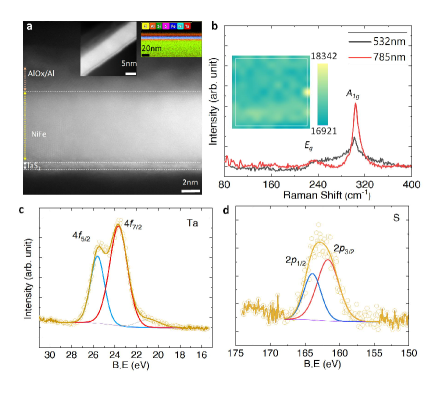
Figure 1 shows the transmission electron microscopy ( TEM) cross sectional image of the Py/TaS2/Al heterostructure. The thickness of the individual layers are found to be similar to the nominal ones. Notably, the thickness of the TaS2 layer is found to be equivalent to one monolayer. In the left inset, the large scale TEM image shows a uniform film and sharp interface of TaS2 in contact with Py layer. Elemental mapping of the stack also supports the uniform growth of all layers in the stack used for device preparation and confirms its composition without interface diffusion or any other impurities. It also confirms that our ferromagnet layer shows less affinity to sulfur because metals having large affinity to sulfur can degrade the 2D characteristics of TMDs [Wu et al., 2019]. Figure 1(b) shows the room temperature Raman spectra recorded on a single layer TaS2 film using two different lasers. Strong fundamental peaks are observed at 305 cm-1 and 231 cm-1 corresponding to the 1T-TaS2 phase [Hirata and Ohuchi, 2001]. The uniformity of the film can be seen in the Raman mapping as recorded around the most intense Raman peak (shown in the inset). Elemental analysis has been performed by X-ray photoelectron spectroscopy (XPS) as presented in Figs. 1(c) and 1(d) for Ta and S, respectively. Observed peaks are de-convoluted into the two spin-orbit split peaks which confirm the TaS2 formation without residual phases [Tison et al., 2004,Zeng et al., 2014]. Further, surface topography and step height scans were also recorded using atomic force microscopy and confirm the monolayer thickness and the smooth interface with Ångström scale flatness of the TaS2 layer (see Supplementary information S4).
III Spin torque ferromagnetic measurements
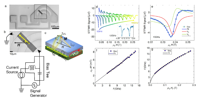
The magnitude of the SOT efficiency governed by the spin torque efficiency ( ) was measured using ST-FMR on the photo-lithographically patterned Py/TaS2 device of size 10020m2. The applied field makes an angle of 45∘ with respect to the current as shown in Fig. 2(a) (scanning electron microscopic (SEM) image of the device). Note that the top Al layer has been removed during the device fabrication process to avoid current shortening from Al (see growth section for details). A SEM image of the measurement circuit is shown in Fig. 2(b). A schematic of the torques acting on the magnetization due to the microwave current IRF is shown in Fig. 2(c). The ST-FMR measurements were performed in field-sweep mode in the frequency range of 5-16 GHz. We have used a lock-in detection technique with an IRF current frequency modulation of 1000 Hz at 9 dB microwave power (see Supplementary information S4 and S5 for details of the measurements and calibration).
The rf current generates an Oersted field as well as spin-orbit torques in presence of the magnetic field and acts as torques on the magnetization of Py. The IRF induced torque acting on the Py layer generates a sustained precession of the magnetization, which mixes with the anisotropic magnetoresistance and spin Hall magnetoresistance of Py creating a dc mixing voltage Vmix. This rectified mixing voltage provides the information of the material parameters and torques acting on the magnetization, which is written as [Kumar et al., 2017], . Here, V0 is the amplitude of the mixing voltage and and are symmetric and antisymmetric Lorentzian functions, respectively. and are symmetric and antisymmetric weight factors, respectively, where , , , , , , and are the magnetic permeability in free space, electronic charge, thickness of ferromagnet layer, rf-spin current density, saturation magnetization, microwave field, resonance field and effective magnetization, respectively.
Figure 2 (d) shows the ST-FMR spectra together with fits using the equation for Vmix, which give the line-shape parameters. The ST-FMR spectra for positive and negative magnetic field scans are shown in the inset (at 12 GHz). It is to be noted that the peak changes its sign on changing the direction of the external magnetic field indicating a damping-like torque () and ruling out the possibility of a dominating Oersted field generated torque (). The symmetric and anti-symmetric amplitudes have been separately fitted to the spectra; an example for the spectrum recorded at 15 GHz is shown in Fig. 2(e). The effective damping () of the TaS2/Py bilayer is evaluated by fitting the H versus data (as shown in Fig. 2(f)) using the equation , where is the linewidth contribution from inhomogeneity in the magnetic film and is the angular microwave frequency. From the fitting, the values of effective damping is found to be 0.00670.0007, which matches well with the bulk value of Py [Zhao et al., 2016]. The inhomogeneous linewidth is found be 0.200.02mT, which is quite small and indicative of a smooth and clean interface of the Py/TaS2 heterostructure. Further, and the anisotropy field () values have been calculated by fitting the versus data to the Kittel equation, = , yielding 0.9020.004T and 1.80.4mT, respectively. The values of of TaS2/Py is measured using a QD-MPMS setup and found to be 1.000.02 T (see supplementary information S5 for details), which is consistent with the value extracted from the ST-FMR results considering the out-of-plane anisotropy field contribution to the effective magnetization.
From the line-shape parameters, the value of the spin torque efficiency is evaluated using the standard line-shape analysis method [Liu et al., 2011], and found to be 0.0230.01. However, in this method it is assumed that the symmetric component is purely from a damping-like torque, disregarding a possible contribution from spin pumping due to the inverse spin Hall effect and can therefore yield erroneous values for the SOT efficiency [Tserkovnyak et al., 2002; Demasius et al., 2016; Saitoh et al., 2006]. Concomitantly, the antisymmetric component is considered as an Oersted field generated torque component but it is again a naive approximation [Demasius et al., 2016]. Moreover, line-shape analysis also shows a frequency dependency [Liu et al., 2011], which may lead to the wrong estimation of the effective spin torque efficiency. Hence, to determine a reliable value of the effective spin torque efficiency and evidence of damping-like torque, we use the so called damping modulation scheme by applying a dc-current during the ST-FMR measurement, where spin pumping due to the inverse spin Hall effect and field-like contributions are insignificant.
IV Current induced modulation/changes of effective damping in TaS2/Py device
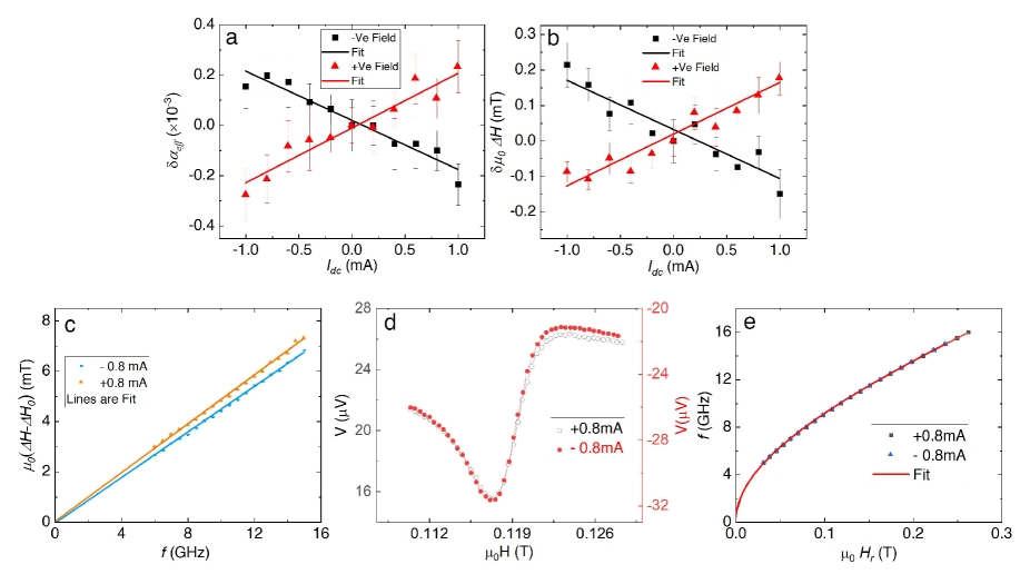
In this method, the dc-current induced non-equilibrium spin accumulation at the interface, resulting due to the spin Hall effect in TaS2 , acts as a torque on the Py magnetization resulting in a change of the effective damping as described by[Liu et al., 2011,Demasius et al., 2016], . The effective spin torque efficiency using the dc-current induced change of the damping is defined as the ratio of spin to charge current density, . Here, , where RPy, R and Ad are the resistances of permalloy and TaS2, respectively, and the cross sectional area of the device. is the angle between the magnetization and the applied field which is 45∘ in our case. Figure 3(a) shows the change/modulation of effective damping as a function of the dc-current (Idc). For comparison, the values are plotted for the two directions of magnetic field scan. The corresponding changes of with dc-current, i.e., are shown in Fig. 3(b). The slopes of the versus Idc curves for the two field directions are almost equal, which confirm that the damping-like torque acting on the magnetization in our Py/TaS2 bilayer is due to the SHE generated spin current. The slope of the change in with dc-current () is 2.170.2110-4/mA and 1.950.1710-4/mA for positive and negative applied fields, respectively. Using the measured resistance values of Py (225 ) and TaS2 (952 ) (see Supplementary information S6 for details of the resistance measurements) in the equation for JC,dc, the value is found to be 0.250.03. Within the experimental uncertainty, the values of the spin torque efficiency are same for both positive and negative field scans. The obtained value is better than values reported for other TMDs [Zhao et al., 2020; Shi et al., 2019; Xu et al., 2020]. The intercept with the current axis is known as the critical current density for auto-oscillations and is estimated to be 5.131010 A/m2. The spin Hall conductivity () in units of /2e is found to be 2.63105 /2e , which is about 50 times smaller than the value reported for the topological insulator Bi0.9Sb0.1/MnGa [Khang et al., 2018], 100 times larger than for the field-like torque dominated semiconducting TMDs MoSe2 and WS2 [Shao et al., 2016], 10 times larger than for the conducting TMD NbSe2[Guimaraes et al., 2018] and comparable to that of the Pd1-xPtx alloy reported to exhibit a strong damping-like SOT [Zhu et al., 2019]. Topological insulators suffer from issues realted to industrial compatibility [Pai, 2018], while heavy metals and alloys have limitations with respect to the spin diffusion length due to the spin relaxation being controlled by the Elliot-Yafet [Zimmermann et al., 2012] and Dyakonov-Perel [Long et al., 2016] scattering mechanisms. The conducting TMD 1T-TaS2 investigated in this work is an industrial compatible material as well as easy to fabricate for SOT devices and therefore avoid such limitations. Moreover, 1T-TaS2 provides rich physics due to its inherent property of charge density wave fluctuations where electrons collectively may carry a charge current in a highly correlated fashion.
The dc-current induced changes of the effective damping can also be seen in the versus results shown in Fig. 3(c) for positive and negative dc-currents. The current distribution in the heterostructure was evaluated and it was found that 19% of the current is flowing through the 1T-TaS2 layer (see Supplementary information S8). Consequently, the Oersted field in the 1T-TaS2 layer is found to be 0.012mT/mA, which is very small, and it is therefore concluded that the field-like torque contribution generated by dc-current passing through TaS2 layer can be neglected. The ST-FMR spectra and resonance field plots shown for two currents in Figs. 3(d) and 3(e), respectively, show no change during current polarity reversal, which is indicative of negligible field-like torque contributions. However, a small field-like torque contribution can arise from the unavoidable interface symmetry breaking [Amin and Stiles, 2016a,Amin and Stiles, 2016b], which is discussed in Supplementary information S10.
V Validation of dc-current induced damping-like torque in TaS2/Py device
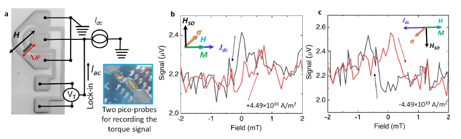
Magnetization switching in presence of in-plane field at constant dc-current In presence of a charge current, the magnetization dynamics is described by the modified Landau-Lifshitz-Gilbert equation and follows the Slonczewski model where the additional torque is added due to the spin-orbit interaction (SOI) induced SHE and can be expressed as [Liu et al., 2011,Slonczewski, 2002], . Here, the first and second terms account for the precessional motion and relaxation of the magnetization towards the equilibrium direction, respectively. The third and fourth terms represent the damping-like and field-like torques, respectively, induced by the charge current. These torques are orthogonal to the normalized magnetization , and and are the damping-like and field-like torque weight factors, respectively. The total field is given by , where and are the Rashba-Edelstein and Oersted field contributions, respectively. Symbols , , and are used as notations for the spin polarization, gyromagnetic ratio, effective field and charge current density, respectively. The damping-like torque acts as an out-of-plane magnetic field, [Khang et al., 2018], whose amplitude can be evaluated from . Using the values for the charge-spin conversion efficiency (0.25), dc-current density (4.49 1010A/m2 at 4 mA dc-current) and the saturation magnetization (820 kA/m) of Py, the value of is found to be 324 A/m. Here, the transverse voltage signal has been measured in an in-plane magnetic field at two (positive and negative) dc-currents (see Supplementary information S1 for details of the measurement). Figures 4(b) and 4(c) show the voltage signal recorded at positive and negative current densities, respectively. At +4.491010 A/m2, a traditional hysteresis loop is formed while changing the dc-current to -4.491010A/m2, both and HSO reverse directions yielding an inverted hysteresis loop, which is in consonance with the behaviour of the SOT [Khang et al., 2018,Li et al., 2018,Fan et al., 2013]. This magnetization switching indicates a sizable damping-like toque in Py/TaS2. The Hall voltage hysteresis was also recorded using a Hall bar structure as is shown in Supplementary information S11. Further, using micromagnetic simulations, the switching of the in-plane magnetization for different current amplitudes has also been studied (Supplementary information S12), which supports the observation of inverted hysteresis loops in experiments.
Angular dependent Planar Hall Effect (PHE) for spin-orbit torques Planar Hall effect (PHE) measurements have received much attention for characterizing the spin orbit torques (SOTs) in the in-plane magnetized systems [Fan et al., 2013,Mahendra et al., 2018,Kawaguchi et al., 2013]. Figure 5(a) shows a scanning electron microscope (SEM) image of the Hall device used for planar Hall effect measurements. A schematic of the measurement circuit has been added to the image. In the planar Hall measurement, the sample is rotated 360 degrees at fixed dc-current. The vector representation of the planar Hall effect is shown in Fig. 5(b), where is the angle between the current direction and the applied field and is the angle between the current direction and the magnetization vector. The theoretical background of the planar Hall effect is discussed in Supplemenetary information S11. Figure 5(c) shows the planar Hall effect signal () versus recorded for two dc-currents of same magnitude but of opposite polarity. A magnetic field of 0.4 T was used for the measurements, which was enough for suppressing the field-like torque contribution.
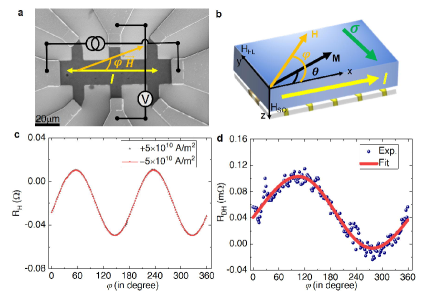
The planar Hall Effect measured at different magnetic fields and currents are discussed in the Supplementary information S11. The difference between the curves () is plotted as a function of in Fig. 5(d), which embraces the dominance of the damping-like torque. The versus curve was fitted using Eq. S12 (see Supplementary information S11) with and as fitting parameters. The field determines the amount of damping-like torque acting on the ferromagnetic layer. The value is found to be 2.5 Oe per 1010 A/m2, from which the spin torque efficiency () has been obtained by using the expression, . The field-like contribution has been found to be -0.02 Oe per 1010 A/m2. The dc-current density can be calculated by considering the dimensions of the device and the conductivity values at a dc-current value of 4.5 mA, yielding a dc-current density of 5 1010 A/m2. Using the thickness and saturation magnetization of the Py layer, is found to be 0.43 which is larger then the value obtained using the ST-FMR analysis. Therefore, it is confirmed without doubt that a monolayer of 1T-TaS2 produces a damping-like torque acting on the Py magnetization.
VI Discussion
It is to be pointed that the possibility of a finite field-like torque contribution is not ruled out (see Supplementary information S10) in this work, which is reasonable and cannot be disentangled in SOT based systems [Amin and Stiles, 2016a,Amin and Stiles, 2016b,Kim et al., 2017]. There has been no clear evaluation of the critical current density and spin torque efficiency in previously reported results for TMD/FM heterostructures [Guimaraes et al., 2018,Shao et al., 2016]. The quantitative estimation of the spin Hall conductivity and auto-oscillations current density in our Py/TaS2 hold valuable information for several spintronic applications. Evidently, the interface of our Py/TaS2 bilayer, as confirmed by cross-sectional TEM and supported by parameters extracted from X-ray reflectivity measurements, is clean in contrast to other works using exfoliated sheets and non-uniform growth where extrinsic contributions from strain and defect related issues [Guimaraes et al., 2018,Xu et al., 2020,Zibouche et al., 2014] reduce the charge-spin conversion efficiency.
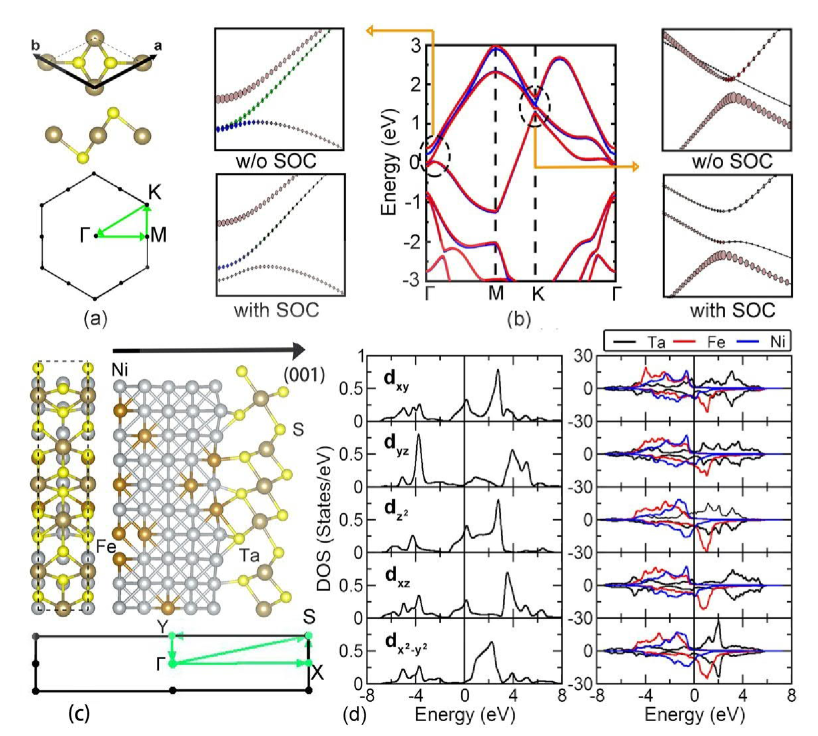
First principles calculations based on density functional theory reveal the role of SOC for lifting the degeneracy in the band structure of TaS2/Py. Figure 6 shows the energy band structures without and with the inclusion of SOC for both pristine TaS2 and Py/ TaS2 systems. A detailed discussion of the structural and electronic properties is presented in the Supplementary information S2. For pristine TaS2, the effects of SOC are clearly observed at and K points (see the expanded views). Specifically, at the point, the degenerate dxz and dyz bands are split due to SOC. It should be noted that this degeneracy is already lifted by the lower symmetry present at the the interface between TaS2 and Py due to the distorted atomic structures. On top of that, further splitting occurs due to the presence of SOC. Therefore, one can conclude that a sizeable redistribution of band structure and hence the splitting of states due to the interface occurs, which becomes responsible for a prominent damping like torque. To highlight the contribution from different d-orbitals, we show in Fig. 6(d) the orbital projected DOSs of Ta in pristine TaS2 and also for the TaS2/Py bilayer. Moreover, projected DOSs of d-orbitals of Fe and Ni in Py are shown to reveal features of hybridization. As our energy range of interest is in the vicinity of the Fermi level, we will consider the electronic states within that energy range. It is observed that in the pristine material, dxy, d and dxz are the orbitals of interest. However, for the bilayer, the d orbital for both spin channels is quite prominent at the Fermi level and its vicinity. Moreover, for the spin-down channel, a hybridization between the d orbitals of Ta and Ni is seen for the spin-down channel.
VII Conclusions
In conclusion, the damping-like spin torque efficiency has been carefully investigated in the Py/TaS2 bilayer using spin-torque ferromagnetic resonance and Hall effect measurements. Employing effective damping modulation or changes with dc-current, the effective spin torque efficiency is found to be 0.250.03. Angle dependent planar Hall effect measurements verify the spin-torque efficiency and clearly reveal the dominance of damping-like torque in our TaS2/Py bilayer. Further, the microscopic origin of the observed dominance of damping-like torque has been substantiated by DFT calculations. The observation of a dominating damping-like torque in just one monolayer provides a path for how to use TaS2 in future spin-orbitronic devices.
Acknowledgements.
The Swedish Research Council ( VR) supports this work, grant no: 2017-03799. Authors thank Seda Ullusoy for SEM imaging. We thank CWT for providing cross section TEM measurements.References
- Emori et al. (2013) S. Emori, U. Bauer, S.-M. Ahn, E. Martinez, and G. S. Beach, Nature materials 12, 611 (2013).
- Safeer et al. (2016) C. Safeer, E. Jué, A. Lopez, L. Buda-Prejbeanu, S. Auffret, S. Pizzini, O. Boulle, I. M. Miron, and G. Gaudin, Nature nanotechnology 11, 143 (2016).
- Garello et al. (2013) K. Garello, I. M. Miron, C. O. Avci, F. Freimuth, Y. Mokrousov, S. Blügel, S. Auffret, O. Boulle, G. Gaudin, and P. Gambardella, Nature nanotechnology 8, 587 (2013).
- Chen et al. (2016) T. Chen, R. K. Dumas, A. Eklund, P. K. Muduli, A. Houshang, A. A. Awad, P. Dürrenfeld, B. G. Malm, A. Rusu, and J. Åkerman, Proceedings of the IEEE 104, 1919 (2016).
- Kim et al. (2013) J. Kim, J. Sinha, M. Hayashi, M. Yamanouchi, S. Fukami, T. Suzuki, S. Mitani, and H. Ohno, Nature materials 12, 240 (2013).
- Zhang et al. (2015) W. Zhang, W. Han, X. Jiang, S.-H. Yang, and S. S. Parkin, Nature Physics 11, 496 (2015).
- Kurebayashi et al. (2014) H. Kurebayashi, J. Sinova, D. Fang, A. Irvine, T. Skinner, J. Wunderlich, V. Novák, R. Campion, B. Gallagher, E. Vehstedt, et al., Nature nanotechnology 9, 211 (2014).
- Manchon et al. (2019) A. Manchon, J. Železnỳ, I. M. Miron, T. Jungwirth, J. Sinova, A. Thiaville, K. Garello, and P. Gambardella, Reviews of Modern Physics 91, 035004 (2019).
- Mahfouzi et al. (2020) F. Mahfouzi, R. Mishra, P.-H. Chang, H. Yang, and N. Kioussis, Physical Review B 101, 060405 (2020).
- Berger et al. (2018) A. J. Berger, E. R. Edwards, H. T. Nembach, O. Karis, M. Weiler, and T. Silva, Physical Review B 98, 024402 (2018).
- Mellnik et al. (2014) A. Mellnik, J. Lee, A. Richardella, J. Grab, P. Mintun, M. H. Fischer, A. Vaezi, A. Manchon, E.-A. Kim, N. Samarth, et al., Nature 511, 449 (2014).
- Khang et al. (2018) N. H. D. Khang, Y. Ueda, and P. N. Hai, Nature materials 17, 808 (2018).
- Li et al. (2019) P. Li, J. Kally, S. S.-L. Zhang, T. Pillsbury, J. Ding, G. Csaba, J. Ding, J. Jiang, Y. Liu, R. Sinclair, et al., Science advances 5, eaaw3415 (2019).
- Pai (2018) C.-F. Pai, Nature materials 17, 755 (2018).
- Feng et al. (2017) Y. P. Feng, L. Shen, M. Yang, A. Wang, M. Zeng, Q. Wu, S. Chintalapati, and C.-R. Chang, Wiley Interdisciplinary Reviews: Computational Molecular Science 7, e1313 (2017).
- Husain et al. (2018) S. Husain, A. Kumar, P. Kumar, A. Kumar, V. Barwal, N. Behera, S. Choudhary, P. Svedlindh, and S. Chaudhary, Physical Review B 98, 180404 (2018).
- Guimaraes et al. (2018) M. H. Guimaraes, G. M. Stiehl, D. MacNeill, N. D. Reynolds, and D. C. Ralph, Nano letters 18, 1311 (2018).
- Lv et al. (2018) W. Lv, Z. Jia, B. Wang, Y. Lu, X. Luo, B. Zhang, Z. Zeng, and Z. Liu, ACS applied materials & interfaces 10, 2843 (2018).
- Shao et al. (2016) Q. Shao, G. Yu, Y.-W. Lan, Y. Shi, M.-Y. Li, C. Zheng, X. Zhu, L.-J. Li, P. K. Amiri, and K. L. Wang, Nano letters 16, 7514 (2016).
- You et al. (2018) J. You, M. D. Hossain, and Z. Luo, Nano convergence 5, 26 (2018).
- Yun et al. (2015) S. J. Yun, S. H. Chae, H. Kim, J. C. Park, J.-H. Park, G. H. Han, J. S. Lee, S. M. Kim, H. M. Oh, J. Seok, et al., ACS nano 9, 5510 (2015).
- Sanders et al. (2016) C. E. Sanders, M. Dendzik, A. S. Ngankeu, A. Eich, A. Bruix, M. Bianchi, J. A. Miwa, B. Hammer, A. A. Khajetoorians, and P. Hofmann, Physical Review B 94, 081404 (2016).
- Wang et al. (2018) X. Wang, H. Liu, J. Wu, J. Lin, W. He, H. Wang, X. Shi, K. Suenaga, and L. Xie, Advanced Materials 30, 1800074 (2018).
- Navarro-Moratalla et al. (2016) E. Navarro-Moratalla, J. O. Island, S. Manas-Valero, E. Pinilla-Cienfuegos, A. Castellanos-Gomez, J. Quereda, G. Rubio-Bollinger, L. Chirolli, J. A. Silva-Guillén, N. Agraït, et al., Nature communications 7, 1 (2016).
- Fu et al. (2016) W. Fu, Y. Chen, J. Lin, X. Wang, Q. Zeng, J. Zhou, L. Zheng, H. Wang, Y. He, H. He, et al., Chemistry of Materials 28, 7613 (2016).
- Wu et al. (2019) R. J. Wu, S. Udyavara, R. Ma, Y. Wang, M. Chhowalla, T. Birol, S. J. Koester, M. Neurock, and K. A. Mkhoyan, Physical Review Materials 3, 111001 (2019).
- Hirata and Ohuchi (2001) T. Hirata and F. Ohuchi, Solid state communications 117, 361 (2001).
- Tison et al. (2004) Y. Tison, H. Martinez, I. Baraille, M. Loudet, and D. Gonbeau, Surface science 563, 83 (2004).
- Zeng et al. (2014) Z. Zeng, C. Tan, X. Huang, S. Bao, and H. Zhang, Energy & Environmental Science 7, 797 (2014).
- Kumar et al. (2017) A. Kumar, S. Akansel, H. Stopfel, M. Fazlali, J. Åkerman, R. Brucas, and P. Svedlindh, Physical Review B 95, 064406 (2017).
- Zhao et al. (2016) Y. Zhao, Q. Song, S.-H. Yang, T. Su, W. Yuan, S. S. Parkin, J. Shi, and W. Han, Scientific reports 6, 22890 (2016).
- Liu et al. (2011) L. Liu, T. Moriyama, D. Ralph, and R. Buhrman, Physical review letters 106, 036601 (2011).
- Tserkovnyak et al. (2002) Y. Tserkovnyak, A. Brataas, and G. E. Bauer, Physical review letters 88, 117601 (2002).
- Demasius et al. (2016) K.-U. Demasius, T. Phung, W. Zhang, B. P. Hughes, S.-H. Yang, A. Kellock, W. Han, A. Pushp, and S. S. Parkin, Nature communications 7, 1 (2016).
- Saitoh et al. (2006) E. Saitoh, M. Ueda, H. Miyajima, and G. Tatara, Applied physics letters 88, 182509 (2006).
- Zhao et al. (2020) B. Zhao, D. Khokhriakov, Y. Zhang, H. Fu, B. Karpiak, A. M. Hoque, X. Xu, Y. Jiang, B. Yan, and S. P. Dash, Physical Review Research 2, 013286 (2020).
- Shi et al. (2019) S. Shi, S. Liang, Z. Zhu, K. Cai, S. D. Pollard, Y. Wang, J. Wang, Q. Wang, P. He, J. Yu, et al., Nature nanotechnology 14, 945 (2019).
- Xu et al. (2020) H. Xu, J. Wei, H. Zhou, J. Feng, T. Xu, H. Du, C. He, Y. Huang, J. Zhang, Y. Liu, et al., Advanced Materials , 2000513 (2020).
- Zhu et al. (2019) L. Zhu, K. Sobotkiewich, X. Ma, X. Li, D. C. Ralph, and R. A. Buhrman, Advanced Functional Materials 29, 1805822 (2019).
- Zimmermann et al. (2012) B. Zimmermann, P. Mavropoulos, S. Heers, N. H. Long, S. Blügel, and Y. Mokrousov, Physical review letters 109, 236603 (2012).
- Long et al. (2016) N. H. Long, P. Mavropoulos, D. S. Bauer, B. Zimmermann, Y. Mokrousov, and S. Blügel, Physical Review B 94, 180406 (2016).
- Amin and Stiles (2016a) V. P. Amin and M. D. Stiles, Physical Review B 94, 104419 (2016a).
- Amin and Stiles (2016b) V. Amin and M. Stiles, Physical Review B 94, 104420 (2016b).
- Slonczewski (2002) J. Slonczewski, Journal of magnetism and magnetic materials 247, 324 (2002).
- Li et al. (2018) P. Li, W. Wu, Y. Wen, C. Zhang, J. Zhang, S. Zhang, Z. Yu, S. A. Yang, A. Manchon, and X.-x. Zhang, Nature communications 9, 1 (2018).
- Fan et al. (2013) X. Fan, J. Wu, Y. Chen, M. J. Jerry, H. Zhang, and J. Q. Xiao, Nature communications 4, 1 (2013).
- Mahendra et al. (2018) D. Mahendra, R. Grassi, J.-Y. Chen, M. Jamali, D. R. Hickey, D. Zhang, Z. Zhao, H. Li, P. Quarterman, Y. Lv, et al., Nature materials 17, 800 (2018).
- Kawaguchi et al. (2013) M. Kawaguchi, K. Shimamura, S. Fukami, F. Matsukura, H. Ohno, T. Moriyama, D. Chiba, and T. Ono, Applied Physics Express 6, 113002 (2013).
- Kim et al. (2017) K.-W. Kim, K.-J. Lee, J. Sinova, H.-W. Lee, and M. D. Stiles, Physical Review B 96, 104438 (2017).
- Zibouche et al. (2014) N. Zibouche, A. Kuc, J. Musfeldt, and T. Heine, Annalen der Physik 526, 395 (2014).