Comparison of Constrained and Unconstrained Human Grasp Forces Using Fingernail Imaging and Visual Servoing
Abstract
Fingernail imaging has been proven to be effective in prior works [1, 2] for estimating the 3D fingertip forces with a maximum RMS estimation error of 7%. In the current research, fingernail imaging is used to perform unconstrained grasp force measurement on multiple fingers to study human grasping. Moreover, two robotic arms with mounted cameras and a visual tracking system have been devised to keep the human fingers in the camera frame during the experiments. Experimental tests have been conducted for six human subjects under both constrained and unconstrained grasping conditions, and the results indicate a significant difference in force collaboration among the fingers between the two grasping conditions. Another interesting result according to the experiments is that in comparison to constrained grasping, unconstrained grasp forces are more evenly distributed over the fingers and there is less force variation (more steadiness) in each finger force. These results validate the importance of measuring grasp forces in an unconstrained manner in order to study how humans naturally grasp objects.
I INTRODUCTION
The complexity of a human hand and the fact that it can reach so many degrees of freedom make it difficult to study its motor behavior during a grasp or manipulation task. There is a significant gap in our understanding of how the human brain can learn and execute these motor behaviors. In order to address this gap and understand the sensorimotor control mechanisms that are employed by the central nervous system, the force collaboration strategies among the fingers must be studied in a totally natural manner. Improvement in our knowledge of human grasp strategies may be used almost immediately in different areas, including robotics, haptics, human-robot interactions, rehabilitation, and bioengineering [3, 4, 5, 6]. Moreover, The increased understanding of precision grasping will result in more accurate mathematical modeling of dexterous grasping [7].
The main concern in human grasp force study is to measure the applied forces at the fingerpad on multiple fingers under natural conditions during experiments i.e., without restricting the human’s haptic senses or constraining how the human grasps an object. Classical methods of studying human grasping require fingers to be placed on a set of pre-specified locations on an instrumented object where force sensors are mounted [8, 9]. In these methods, finger contact positions are defined by the locations of the force sensors along the sides of the object to be grasped. Previous studies have shown that unlike the unconstrained posture, constraining the finger placement can create a meaningful difference in force distribution over the fingers [10]. However these studies only involved the index finger and thumb, since their instrumented objects cannot allow for independent measurement of multiple unconstrained finger forces. Considering the fact that humans do finger placement so efficiently, it is necessary to measure grasp forces on multiple fingers in an unconstrained manner. There have been several methods developed for unconstrained grasp force measurement [11, 12, 13]. However, these techniques are either not capable of measuring shear forces, or may interfere with hand movements and haptic sense due their complex de,sign, and cannot be used for the purpose of studying grasp force. Thus, the goal of this paper is to conduct multifingered grasping experiments under both constrained and unconstrained conditions to study the effect of these conditions on the observed force synergies. For this purpose, we have used the fingernail imaging method, which has been developed by the authors, as a tool for measuring the forces.
I-A Fingernail Imaging
The fingernail imaging technique, which has been developed in the previous works, is an effective method of 3D fingertip force estimation without imposing any constraint on finger placement [1]. For this method, forces are estimated by analyzing the coloration patterns on fingernail due to the blood flow change in tissues beneath the nail when the fingertip comes in contact with objects. This method is capable of estimating fingertip forces along all three directions simultaneously with a maximum estimation RMS error of N, which was 7% of the full range of forces measured. [14, 15, 16]
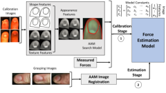
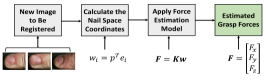
The capability of the fingernail imaging method is, however, limited by the ability to maintain a proper view of the human fingernails with one or more cameras as the fingernails translate and rotate within a workspace during a dynamic grasping task. To overcome this problem, cameras can be mounted on the end-effectors of robotic arms, and a visual servoing tracking system can be employed to ensure that the fingers are in the camera view all times. As a result, grasp force estimation using fingernail imaging is a two-step process (Fig. 1): 1) building a force estimation model based on a collected set of calibration data including fingernail images and applied forces 2) applying the force estimation model on the new images captured during the grasping experiments. These two steps will be explained in the following sections.
II Experimental Procedure
In order to study the grasp forces under both constrained and unconstrained grasping conditions, data from 6 human subjects (3 male and 3 female) with different fingernail size and texture was recorded.
II-A Training Data Collection
The training data was collected using an automated calibration platform that was developed in the previous work [1]. The data collection experimental setup includes a Magnetic Device (MLDH) that exerts desired force levels according to a hybrid position-force controller with feedback linearization. The calibration desired force space is a Cartesian grid that includes normal force between 0N to 18N and shear forces in the range -3N to 3N and -6N to 6N along x and y axis, respectively. Forces were recorded using a 6-axis force sensor, while fingernail images were captured by an RGB camera. To eliminate the ambient light and to provide uniform lighting during the data collection, an LED lightbox was installed above the human hand to remove any glare on the fingernail. Each of the index, middle, ring and thumb fingers were calibrated individually per each human subject and about 6725 to 7050 images and corresponding forces were recorded for each individual finger.
II-B Grasping Experiments
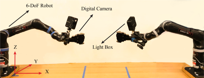
For the grasping experiments, it is desired to keep the fingernails centered in the field of view of the camera and to keep the camera at a preferential distance to the fingernails (to maximize the size of the nails in the image). Using a stationary camera, human subjects cannot be relied upon to keep their fingernails in the camera view. This restriction would limit further research. Therefore, we have employed an autonomous visual tracking system to allow a camera mounted on a robot to track the fingernails during a grasping task. Two 6-DOF robotic arms were chosen for this task. Two PointGrey Flea3 digital cameras mounted on the last link of each robot were also selected for the purpose image capturing during the grasping experiments one with a view of the thumb and the other, the fingers. Two LED light boxes were attached to each robot end-effector to provide the same lighting condition as the one used in calibration experiments. Fig. 2 shows the experimental setup for grasping experiments.
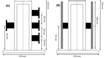
In order to perform grasping tests with both constrained and unconstrained conditions, two grasping objects have been created. The first object is an instrumented T-shaped apparatus with precise grasping locations, where four force sensors are used for measuring the contact forces and validating the estimated forces found by fingernail imaging (Fig. 3(a)). Previous studies have shown that little finger forces are small enough during grasping, that they can be neglected [9]. Hence, only four-fingered grasping has been studied in this research. The second grasping object, which has been designed for unconstrained grasping tests, is the same T-shaped object but, with no pre-defined grasping points, such that the fingers may contact anywhere along the pads on both sides as shown in Fig. 3(b). Moreover, a sticky tape covered the finger placement locations on both objects to increase friction and prevent the fingers from sliding.
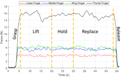
Two sets of grasping tests were carried out to investigate the effect of constraining the grasp, including one with the constrained object and one with the unconstrained object. In both tests, the experimental procedure for each test subject includes reaching for the object, grasping it, lifting it up to 25 cm from its initial position, holding it for 10 sec and replacing the object in its initial position. Subjects could see the instructions for each phase of the experiment as well as an online video of their fingers on a screen in front of them. First, the test subjects were instructed to stand in front of the table with their shoulder aligned with the object, and to have the corresponding hand 20-30 cm from the object. After 5 seconds, they were instructed to put their fingers on the object. After another 3 seconds, which is required to make sure that the fingernails are inside of the camera frame, the subjects were asked to lift the object. The total time needed for this experiment could vary between 45 to 55 secs per each subject and each test was repeated two times per each human subject. To give a better understanding of the four grasping phases, Fig. 4 shows the normal force per each finger over the entire grasping experiment time for one of the human subjects.
III Method and Data Analysis
After data collection for each test subject from both calibration and grasping experiments, the grasp forces are estimated from the fingernail images. In this section, the steps that are needed for force estimation using the fingernail imaging method will be discussed. Moreover, the visual servoing system used for finger tracking will be explained.
III-A Force Estimation Model
Before building any force estimation model, all the fingernail images must be registered and warped to a template to compensate for any scaling, rotation, and translations on the images. The same registration method that was developed in previous works [17] is used in this paper which iteratively uses Active Appearance Models (AAM) to register all of an individual’s data. AAM is the combination of shape and texture models. Thus, each of those models should be determined separately (using Principal Component Analysis (PCA)) and then combined together. Once the shape and texture parameters vectors have been found, the AAM search model can be formed using the following equation:
| (1) |
Where b is the appearance model which is the combination of shape and texture models. and c are defined in [1]. For each new image chosen to be registered, the finger mean shape is found and is placed in an estimated location on the image. Then, the AAM Search Model is applied to find the final location of the finger shape. Finally, the image is warped to the template using a piecewise linear transformation.
Once a new image is warped, the EigenNail Magnitude Model [14] is used to create a force estimation model, which forms a relating mapping between the images coordinates to the force in Nail Space. As the first step, PCA is performed on the calibration images to find the eigenvectors of the data set. The first eigenvectors, which are responsible for 99% of the data variation, will be kept. Then, to find the Nail Space coordinates (), each image is projected onto their eigenvectors. Finally, a least-squares regression is performed to relate the Nail coordinates to the 3D forces. Fig. 5 shows the overall process of force estimation, where images Nail Space coordinates are used as inputs for force estimation model according to the following equation:
| (2) |
Where f is the vector of estimated force, and , and are the coefficients found by multivariable regression.
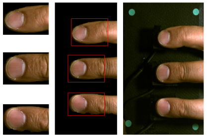
Since each finger has a different force estimation model, fingers must be first detected on each of the captured images from grasping tests (index, middle and ring fingers are in one image) to be used by the estimation model. For this purpose, a simple thresholding color segmentation in HSV color space is used, where fingers are detected by considering a threshold for the H values of the skin color. Finally, the images must be appropriately labeled by order of the fingers. Since the order is always index, middle, and ring (from top to the bottom of the image), it is only necessary to check the order of the detected fingers on the image and label them accordingly. After detecting and labeling each individual finger, a region with the size of pixels around each detected fingernail is cropped and will be used as an input to the force estimation model as shown in Fig. 6.
III-B Visual Servoing
During the grasping experiments, a visual tracking system on each robot controls their motion using feedback information extracted from an image and is based on a mapping between the object features in the image plane and the object’s motion (image-based visual servoing) to ensure that the two robotic arms can follow the fingers all times. Using the eye-in-hand setup allows the same camera that is being used to track the fingers to be simultaneously utilized to capture images of the fingernails for force estimation.
The control scheme used in this paper is based on the principles described in [18]. The controller is designed to use the image-space approach, which ensures that the robot will take the shortest path in image space. The image features that are used for tracking are the centers of a set of four dots that are placed on four corners of the grasping objects. The visual servoing runs at 1KHz, while the images are captured with a frequency of 20Hz with the resolution of pixels. The two robots are controlled independently, while the image capturing of the two cameras is synchronized using a TCP/IP connection between them.
IV Results and Discussion
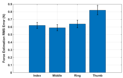
As the first result, Fig. 7 shows the RMS validation error between the measured (using the force sensors) and the estimated forces in both normal and shear directions during the constrained grasping. The RMS estimation errors for each of the fingers are N (the thumb), N (index finger), N (middle finger), and N (ring finger). A Mann-Whitney u test indicates that there is no significant difference in the errors between the estimated and measured forces among each of the four fingers (, ).
![[Uncaptioned image]](/html/2004.02311/assets/x8.png)
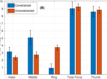
Fig. 8(a) and (b) show the average normal and shear estimated forces for each finger during the 10 seconds hold phase. Since the forces are static during the hold phase, The total force (the overall force applied by the three fingers) must be equal to the thumb force. According to Fig. 8(a) and (b), there is a maximum difference between the total force and the thumb force along both normal and lateral directions which validates the force estimation accuracy. Another interesting result is the force magnitude change in each finger by switching from constrained to unconstrained condition. It can be seen from the figures that the force distribution among the three fingers changes based on the grasping condition and positions of the fingers.
![[Uncaptioned image]](/html/2004.02311/assets/x10.png)
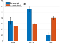
The pairwise u test has been performed on the 10-second average force across all 12 trials (2 trials per each subject) among all three fingers for the two different grasping conditions (Table I). The results indicate that there is a significant difference with confidence in the force magnitude when the grasping condition changes from constrained to unconstrained. However, the results indicate that there is no significant change in the total finger force or thumb force when the condition changes. The change in the thumb force is N for the normal and N for the shear forces, respectively (less than of the overall force range). This indicates that while the overall force required to grasp the object is not significantly affected by constraining the grasp, the distribution of forces among the individual fingers is. Moreover, It may be also seen from the error bars that there is more force variation in fingers across the subjects/trials for constrained grasping. Comparing the pairwise u test result for the variance of each group, shows that there is a significant difference in each finger force variance between the two grasping conditions. In order to better explain the force disstribution change over the three fingers, each finger force has been normalized by the total force of each trial, and then the average normalized forces for three fingers are plotted as a percentage in Fig. 9(a) and (b). It may be seen that the index finger ( for normal and for shear) and the middle finger forces ( for normal and for shear) have decreased, while the ring finger force ( for normal and for shear) has increased by switching to the unconstrained condition.
![[Uncaptioned image]](/html/2004.02311/assets/x12.png)
| Normal Force | Shear Force | |
|---|---|---|
| Index | , | , |
| Middle | , | , |
| Ring | , | , |
| Thumb | , | , |
From Fig. 9, it can be observed that the forces are more evenly distributed among the three fingers for unconstrained grasping. Force variance (across the fingers) in each trial is considered as a metric of balance. The average force variances are found as and for constrained condition, and and for unconstrained condition. the pairwise u test for the two groups of constrained and unconstrained variances shows that there is a significant difference with confidence in force balance among the three fingers.
![[Uncaptioned image]](/html/2004.02311/assets/x14.png)
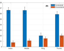
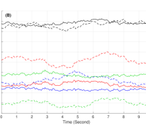
Another interesting result from the grasping tests is the steadiness of the applied forces during the hold phase in each finger. Fig. 10(a) and (b) show the average force variation over the 10 seconds period for each individual finger under the two grasping conditions. It can be observed that the forces are more steady during the unconstrained test. The variance (over time) of each finger force during the hold phase in each trial is considered as a metric of steadiness ( and ). Fig. 11(a) and (b) compare the average of these variances ( and ) for the two grasping conditions. The result of the u test for the two groups of constrained and unconstrained variances indicates that there is a significant difference with confidence in force steadiness by switching from constrained to the unconstrained condition.
V CONCLUSIONS
This paper demonstrates the effectiveness of the fingernail imaging method in studying the unconstrained grasp forces as well as the effect of grasping constraints on force synergy among fingers. To overcome the problem of keeping fingers in the field of view of the cameras, two six degree-of-freedom robotic arms with the eye-in-hand camera setup and a visual servoing tracking system have been devised to ensure that there always exists a proper view of the human fingernails during the grasping experiments. The preliminary experimental results show the accuracy of force measurement based on fingernail imaging for estimating dynamic grasping forces with a maximum RMS error of N force over the four fingers, which is comparable to prior fingernail imaging work on quasi-static forces [1, 2].
The experimental results have also demonstrated a never-before-seen comparison of constrained vs. unconstrained grasp force distributions during a dynamic grasping task. Based on the experimental results, the main conclusions are: (1) Although the total grasp force is not significantly affected, the individual finger forces are significantly different for the two grasping conditions. The index and the middle finger forces have decreased, while the ring finger force has increased by switching to the unconstrained condition. (2) The forces are more evenly distributed (more balanced) among the three fingers under the unconstrained condition compared to the constrained grasping. (3) There is more consistency/repeatability in finger forces across the subjects/trials for unconstrained grasping. (4) By looking just at a single finger, it can be concluded that there is more force variation in constrained grasping over time. In other words, the unconstrained forces are more steady versus time. The combined observations that unconstrained grasp forces are more evenly distributed, repeatable, and steady is strong evidence that it is important to not constrain grasping in order to accurately study the natural grasping synergies of humans.
Future work will include the study of dynamic force behaviors during a manipulation task, which consists of both grasping and positioning stages. Additionally, the effect of changing the object center of mass on digit placement both before and during the grasping task will be studied in future research. Finally, it is the authors’ goal to design a system of multiple collaborative robots to interactively work with a human subject in a workspace based on the estimated applied finger forces, while tracking their hands.
References
- [1] T. R. Grieve, J. M. Hollerbach, and S. A. Mascaro, “3-d fingertip touch force prediction using fingernail imaging with automated calibration,” IEEE Transactions on Robotics, vol. 31, no. 5, pp. 1116–1129, 2015.
- [2] T. R. Grieve, J. M. Hollerbach, and S. A. Mascaro, “Optimizing fingernail imaging calibration for 3d force magnitude prediction,” IEEE transactions on haptics, no. 1, pp. 69–79, 2016.
- [3] A. S. Gailey, S. B. Godfrey, R. E. Breighner, K. L. Andrews, K. D. Zhao, A. Bicchi, and M. Santello, “Grasp performance of a soft synergy-based prosthetic hand: a pilot study,” IEEE Transactions on Neural Systems and Rehabilitation Engineering, vol. 25, no. 12, pp. 2407–2417, 2017.
- [4] P. Polygerinos, F. Sebastian, Q. Fu, and M. Santello, “Soft robotic haptic interface with variable stiffness for rehabilitation of sensorimotor hand function,” June 6 2019. US Patent App. 16/212,205.
- [5] M. Santello, M. Bianchi, M. Gabiccini, E. Ricciardi, G. Salvietti, D. Prattichizzo, M. Ernst, A. Moscatelli, H. Jörntell, A. M. Kappers, et al., “Hand synergies: integration of robotics and neuroscience for understanding the control of biological and artificial hands,” Physics of life reviews, vol. 17, pp. 1–23, 2016.
- [6] S. B. Godfrey, K. D. Zhao, A. Theuer, M. G. Catalano, M. Bianchi, R. Breighner, D. Bhaskaran, R. Lennon, G. Grioli, M. Santello, et al., “The softhand pro: Functional evaluation of a novel, flexible, and robust myoelectric prosthesis,” PloS one, vol. 13, no. 10, p. e0205653, 2018.
- [7] K. Mojtahedi, Q. Fu, and M. Santello, “Extraction of time and frequency features from grip force rates during dexterous manipulation,” IEEE Transactions on Biomedical Engineering, vol. 62, no. 5, pp. 1363–1375, 2015.
- [8] J. F. Soechting and M. Flanders, “Sensorimotor control of contact force,” Current opinion in neurobiology, vol. 18, no. 6, pp. 565–572, 2008.
- [9] Q. Fu, W. Zhang, and M. Santello, “Anticipatory planning and control of grasp positions and forces for dexterous two-digit manipulation,” Journal of Neuroscience, vol. 30, no. 27, pp. 9117–9126, 2010.
- [10] J. R. Lukos, J. Y. Choi, and M. Santello, “Grasping uncertainty: effects of sensorimotor memories on high-level planning of dexterous manipulation,” Journal of neurophysiology, vol. 109, no. 12, pp. 2937–2946, 2013.
- [11] Y. Tanaka, A. Sano, M. Ito, and H. Fujimoto, “A novel tactile device considering nail function for changing capability of tactile perception,” in International Conference on Human Haptic Sensing and Touch Enabled Computer Applications, pp. 543–548, Springer, 2008.
- [12] A. Naceri, A. Moscatelli, M. Santello, and M. O. Ernst, “Coordination of multi-digit positions and forces during unconstrained grasping in response to object perturbations,” in Haptics Symposium (HAPTICS), 2014 IEEE, pp. 35–40, IEEE, 2014.
- [13] E. Battaglia, M. Bianchi, A. Altobelli, G. Grioli, M. G. Catalano, A. Serio, M. Santello, and A. Bicchi, “Thimblesense: a fingertip-wearable tactile sensor for grasp analysis,” IEEE transactions on haptics, vol. 9, no. 1, pp. 121–133, 2016.
- [14] T. R. Grieve, J. M. Hollerbach, and S. A. Mascaro, “Force prediction by fingernail imaging using active appearance models,” in World Haptics Conference (WHC), 2013, pp. 181–186, IEEE, 2013.
- [15] N. Fallahinia, S. Harris, and S. Mascaro, “Grasp force sensing using visual servoing and fingernail imaging,” in ASME 2018 Dynamic Systems and Control Conference, pp. V001T04A010–V001T04A010, American Society of Mechanical Engineers, 2018.
- [16] N. Fallahinia and S. Mascaro, “Feasibility study of force measurement for multi-digit unconstrained grasping via fingernail imaging and visual servoing,” in Proceedings of the ASME 2019 Dynamic Systems and Control Conference, vol. 3, American Society of Mechanical Engineers, 10 2019.
- [17] T. R. Grieve, J. M. Hollerbach, and S. A. Mascaro, “Fingernail image registration using active appearance models,” in Robotics and Automation (ICRA), 2013 IEEE International Conference on, pp. 3026–3033, IEEE, 2013.
- [18] F. Chaumette and S. Hutchinson, “Visual servo control. i. basic approaches,” IEEE Robotics & Automation Magazine, vol. 13, no. 4, pp. 82–90, 2006.