Elusive Dzyaloshinskii-Moriya interaction in Fe3GeTe2 monolayer
Abstract
Using symmetry analysis and density functional theory calculations, we uncover the nature of Dzyaloshinskii-Moriya interaction in Fe3GeTe2 monolayer. We show that while such an interaction might result in small distortion of the magnetic texture on the short range, on the longrange Dzyaloshinskii-Moriya interaction favors in-plane Néel spin-spirals along equivalent directions of the crystal structure. Whereas our results show that the observed Néel skyrmions cannot be explained by the Dzyaloshinskii-Moriya interaction at the monolayer level, they suggest that canted magnetic texture shall arise at the boundary of Fe3GeTe2 nanoflakes or nanoribbons and, most interestingly, that homochiral planar magnetic textures could be stabilized.
Introduction -
Magnetism in low dimensions has received renewed interest in the past few years with the experimental observation of remnant magnetization in two-dimensional van der Waals materials such as CrI3 Huang2017b , VTe2 Li2018f , CrTe2 Sun2019 , and Fe3GeTe2 Deng2018 . The emergence of robust magnetic order at room temperature is appealing for spintronics applications, and among the ever-increasing family of candidate materials Fe3GeTe2 stands out as a solid paradigm Deng2018 ; Zhang2020a ; Park2020 . As a matter of fact, this material hosts interesting promises: spin-orbit torque Alghamdi2019 ; Wang2019c and anomalous Nernst effect Xu2019 ; Fang2019 have been observed in bilayer heterostructures, and magnetoresistance has been reported in spin-valves Wang2018c ; Albarakati2019 .
Besides these experimental achievements, the recent reports of magnetic skyrmions and other chiral textures in thick Fe3GeTe2 layers Wang2019d ; Ding2019 ; Park2019 are intriguing. As a matter of fact, stable and metastable chiral magnetic textures require the existence of an antisymmetric exchange interaction, called Dzyaloshinskii-Moriya interactionDzyaloshinskii1957 ; Moriya1960 . This interaction only exists in materials lacking inversion symmetry and the specific structure of this interaction determines the nature of the chiral magnetic structures it can stabilize Nagaosa2013 . For instance, in magnetic multilayers the interfacial symmetry breaking promotes the onset of an interfacial Dzyaloshinskii-Moriya interaction of the form that favors Néel skyrmions (e.g., see Ref. Chen2015b, ). Therefore, the observation of Néel-type skyrmions in thick Fe3GeTe2 layerWang2019d ; Ding2019 ; Park2019 is unexpected as the point group of Fe3GeTe2 monolayer prevents the onset of ”interfacial” Dzyaloshinskii-Moriya interaction. However, the point group of Fe3GeTe2 monolayer does not entirely forbid the emergence of chiral effects. As pointed recently by Johansen et al.Johansen2019 , point group symmetry analysis shows that Fe3GeTe2 monolayer exhibits a damping-like spin-orbit torque, while the field-like torque is zero. Since Dzyaloshinskii-Moriya interaction and damping-like torque are related to each other Freimuth2014 , one can expect a non-vanishing Dzyaloshinskii-Moriya interaction but of completely different nature compared to the interfacial one.
In this work, using symmetry analysis and density functional theory (DFT) calculations, we investigate the nature of Dzyaloshinskii-Moriya interaction in Fe3GeTe2 monolayer. We show that while such an interaction might result in small distortion of the magnetic texture on the short range, on the long-wavelength limit Dzyaloshinskii-Moriya interaction favors in-plane Néel spin-spirals along equivalent directions of the crystal structure. Whereas these results show that the observed Néel skyrmions cannot be explained by the Dzyaloshinskii-Moriya interaction at the monolayer level, they suggest that canted magnetic texture shall arise at the boundary of Fe3GeTe2 nanoflakes or nanoribbons and that homochiral planar magnetic textures can be stabilized.
Long-wavelength behavior -
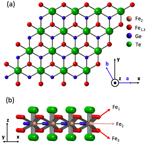
Let us first consider the crystal structure of Fe3GeTe2 monolayer, depicted on Fig. 1. The crystal adopts the point group and can be seen as a stack of three Fe hexagonal lattices in A-B-A configuration. In the following the central Fe element is denoted Fe2 and the Fe elements on the top and bottom planes are referred to as Fe1,3, respectively. One can see by inspection on Fig. 1 that all the three inequivalent Fe elements are located in a chemical environment that lacks inversion symmetry. Therefore, one can expect each magnetic element to experience chiral effects such as Dzyaloshinskii-Moriya interaction and spin-orbit torques in the presence of spin-orbit coupling. However, Fe1 and Fe3 are mirror partners, i.e., related by mirror symmetry. Therefore, any chiral physical quantity on one element is opposite on the other element. In contrast, Fe2 is located in the mirror plane of the crystal and therefore should experience such chiral effects.
As a matter of fact, a first indication of the existence of spin-orbitronics effects was provided by analyzing the point group of Fe3GeTe2 monolayer. For instance, applying these symmetries [improper six-fold rotation about (001), mirror symmetry normal to (110)] to the current-driven field response tensor Zelezny2017 , one obtains a vanishing field-like torque but an unusual non-zero damping-like torque (see also Ref. Johansen2019, )
| (1) |
In this expression, is the torque response coefficient and is the applied electric field. This torque is particularly interesting as it behaves like a non-equilibrium anisotropy energy term Johansen2019 . Of major interest to the present work, one can show that in the limit of small spatial gradients, i.e., in the long-wavelength limit, the Dzyaloshinskii-Moriya tensor has the same symmetry as the damping-like torque response Freimuth2014 . In fact, defining the torque response tensor as and the Dzyaloshinskii-Moriya tensor as , the linear response theory yields . In other word, the torque tensor reads
| (2) |
One can deduce the Dzyaloshinskii-Moriya energy,
| (3) |
Hence, since the Dzyaloshinskii-Moriya interaction is a total derivative, it does not stabilize chiral textures in the long-wavelength limit. However, one could wonder whether this interaction can stabilize magnetic twists at the edges of the magnetic layer, as discussed recently Raeliarijaona2018 ; Hals2017 ; Rohart2013 . To investigate this possibility, let us a magnetic ribbon with easy-plane anisotropy and embedded between two boundaries normal to the direction . The system is translationally invariant along and therefore, spatial gradients are only allowed along , , where is the coordinate along n. In the bulk of the nanoribbon, the magnetization minimizes the energy functional , where is the exchange and the easy plane anisotropy. The general solution is , where is expressed in the frame (, , ). The boundary condition reads Hals2017 ,
| (4) |
where is the boundary-induced Dzyaloshinskii-Moriya field, defined , with being the Dzyaloshinskii-Moriya energy. Solving Eq. (4) at the positions and , we obtain two coupled equations
| (5) | |||
| (6) |
yielding the solution, . However, the total energy of this spin spiral is , which is minimized for . Therefore, the Dzyaloshinskii-Moriya interaction given by Eq. (3) does not favor chiral magnetic textures, even in the case of a planar ferromagnet. We emphasize that the present discussion only concerns the interaction derived in the limit of small spatial gradients. It does not address the possible existence of short-wavelength magnetic textures.
Structural analysis -
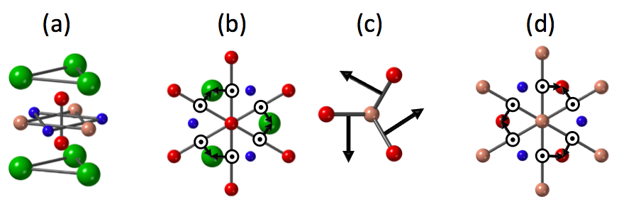
Let us now take a different perspective and consider the atomistic Dzyaloshinskii-Moriya interaction between neighboring magnetic moments. The relevant pairs of neighboring moments are displayed on Fig. 2 together with the Dzyaloshinskii-Moriya vector , defined in the atomistic spin limit . The Dzyaloshinskii-Moriya vector is determined by Moriya’s rules Moriya1960 .
We first consider the Fe1-Fe3 pair, located on each side of the (001) mirror plane [Fig. 2(a)]. Since the axis on which this pair lies has a three-fold rotational symmetry, the Dzyaloshinskii-Moriya vector is necessarily along the axis (5th Moriya rule). But since this axis also possesses a mirror symmetry perpendicular to it, the Dzyaloshinskii-Moriya vector must be also perpendicular to the axis (1st Moriya rule). As a result, there is no Dzyaloshinskii-Moriya interaction between Fe1 and Fe3. Let us now consider the interaction between two Fe1 (or, equivalently, two Fe3) belonging to the same layer [Fig. 2(b)]. Since a mirror plane passes perpendicularly through the center of the Fe1-Fe1 axis, the Dzyaloshinskii-Moriya vector lies along the plane (1st Moriya rule). Considering the three-fold rotational symmetry around , we deduce that the Dzyaloshinskii-Moriya vector is necessarily along . Notice that the Dzyaloshinskii-Moriya vector also possesses an in-plane component that has three-fold symmetry. We now move on to the Fe1-Fe2 pair, depicted on [Fig. 2(c)]. Here, the same symmetry principles apply and we find that the Dzyaloshinskii-Moriya vector must be perpendicular to the Fe1-Fe2 segment. Notice that in the case of the Fe3-Fe2 pair, the Dzyaloshinskii-Moriya vector adopts the opposite orientation. Finally, the interaction between Fe2-Fe2 [Fig. 2(d)] is similar to the one obtained for Fe1-Fe1 so that the Dzyaloshinskii-Moriya vector possesses a constant component and a staggered planar component.
To understand what is the overall influence of these different Dzyaloshinskii-Moriya vectors, one needs to remark that the Dzyaloshinskii-Moriya interactions involving either Fe1 or Fe3 are systematically opposite to each other because of the mirror symmetry normal to the (001) plane. Therefore, one might expect small magnetization canting at the level of the unit cell but no overall effect on the long range. This remark coincides with the absence of long-wavelength interaction emphasized in the previous section. Furthermore, the possible small canting of the magnetic moments in the unit cell could be an explanation for the topological Hall effect reported in Ref. You2019, .
What is particularly interesting is that whereas the in-plane component of the Dzyaloshinskii-Moriya vector is staggered, the perpendicular () component of the Fe2 layer remains constant over the unit cell. Therefore, one expects that at intermediate range (i.e., beyond the size of a unit cell), the atomistic Dzyaloshinskii-Moriya energy reads . This interaction is carried by the central Fe elements and its magnitude is therefore associated with the electrostatic environment of Fe2. The latter remark is important because the only heavy element of the structure is Te, which is located further apart from Fe2. Therefore, one would expect the overall magnitude of the Dzyaloshinskii-Moriya interaction to remain small.
Spin spiral calculations -
To confirm the analysis provided above, we performed DFT calculations on Fe3GeTe2. We used the full-potential linearized augmented-plane-wave (FLAPW) method as implemented in the FLEUR software Fleur . Applying the generalized Bloch theorem Kurz2004 , we first self-consistently compute the total energy of the system for spin spirals with different wavelengths including the scalar-relativistic effects but in the absence of spin-orbit coupling, . Then, we turn on the spin-orbit coupling and compute the spin spiral dispersion at the first order only, . The scalar-relativistic dispersion provides the magnetic exchange parameter , while the difference provides a measure of the magnetic anisotropy (at =0) and Dzyaloshinskii-Moriya interaction Heide2009 ; Ferriani2008 ; Belabbes2016 .
For the structural relaxation, we employed the generalized gradient approximation (GGA) Perdew1996 , obtaining a relaxed lattice constant of 4.01 Å for Fe3GeTe2 monolayer. For the magnetic calculations, we used the local density approximation (LDA) Perdew1981 . In all calculations, we selected the radii of muffi-tin spheres around 2.1 a.u for Ge and Fe, and 2.6 a.u for Te, where a.u is the Bohr radius. The linearized augmented plane-wave basis functions included all wave vectors up to = 3.8 a.u-1 in the interstitial region and in the muffin-tin spheres, and basis functions including spherical harmonics up to = 8 were taken into account. For collinear (non-collinear + spin-orbit coupling), the calculations were performed on a dense mesh of 512 (1024) -points in the full two-dimensional Brillouin zone.
| Element | Spin moment | Orbital moment |
|---|---|---|
| Te1,2 | -0.024 | -0.02 |
| Fe1,3 | 2.267 | 0.083 |
| Fe2 | 1.287 | 0.19 |
| Ge | -0.06 | 0.0065 |
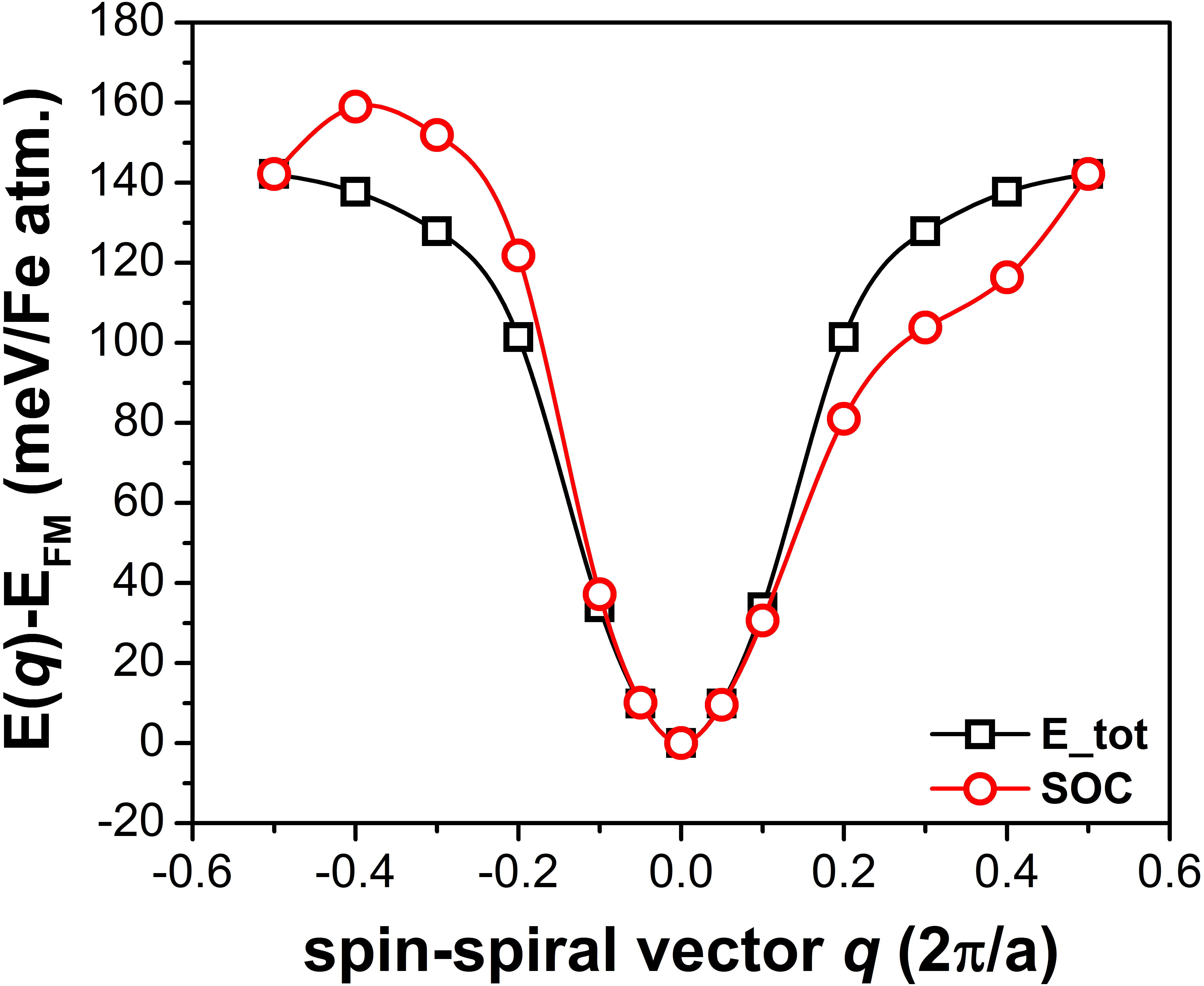
Based on the procedure described above, we obtain the spin- and orbital-resolved magnetic moments displayed in Table 1 and a perpendicular magnetic anisotropy =1.3 meV/Fe. We have performed spin spiral dispersion calculation for the three standard spin spiral configurations: (a) Néel out-of-plane, (b) Bloch out-of-plane and (c) Néel in-plane (see Ref. Belabbes2016b for an explicit representation of these configurations). We found that only the Néel in-plane spin spiral displays Dzyaloshinskii-Moriya interaction, as expected from the previous analysis. For this spiral, the magnetic exchange parameter is =47 meV/Fe. The corresponding spin spiral dispersion along the path is represented on Fig. 3, with (red) and without (black) spin-orbit coupling. One clearly sees that turning on spin-orbit coupling distorts the spin spiral dispersion in an antisymmetric manner. In contrast, neither Néel nor Bloch out-of-plane spin spirals display any antisymmetric contribution upon turning on the spin-orbit coupling (not shown), indicating that the Dzyaloshinskii-Moriya vector does not possess in-plane components.
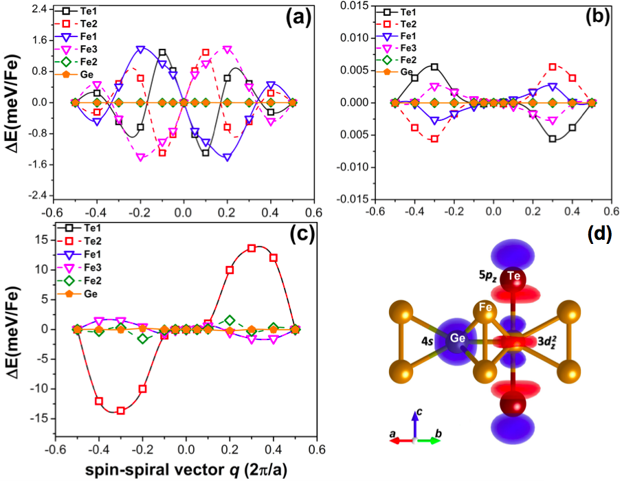
In order to given a complete picture of the microscopic origin of the perpendicular Dzyaloshinskii-Moriya interaction, we analyzed the contribution of the various elements (Fe1,3, Fe2, Te and Ge) on the antisymmetric spin spiral dispersion for the three configurations. The results are displayed on Fig. 4. In the case of Néel out-of-plane spin spiral [Fig. 4(a)], the main contributions come from top and bottom Fe1,3 as well as from the top and bottom Te elements. Interestingly, these contributions are sizable in magnitude but cancel each other by symmetry. In the case of Bloch out-of-plane spin spiral [Fig. 4(b)], we obtain the same cancellation by symmetry but the magnitude of the individual contributions remain extremely small (a few eV/Fe). Such a small magnitude is below the accuracy of our calculations and is therefore insignificant. Finally, for the Néel in-plane spin spiral [Fig. 4(b)], the antisymmetric dispersion is dominated by the hybridization between the 5 orbitals of Te and the 3 orbitals of the central Fe2 element [see Fig. 4(b)]. This hybridization induces a large orbital momentum on Fe2 (0.19), as displayed in Table 1, that is responsible for the observed Dzyaloshinskii-Moriya interaction. In contrast, the Fe1,3 elements have a much smaller contribution. In fact, although they also experience a perpendicular Dzyaloshinskii-Moriya vector [see Fig. 2(b)], they chemical environment does not promote a large orbital moment (0.083) and therefore yields a small Dzyaloshinskii-Moriya interaction.
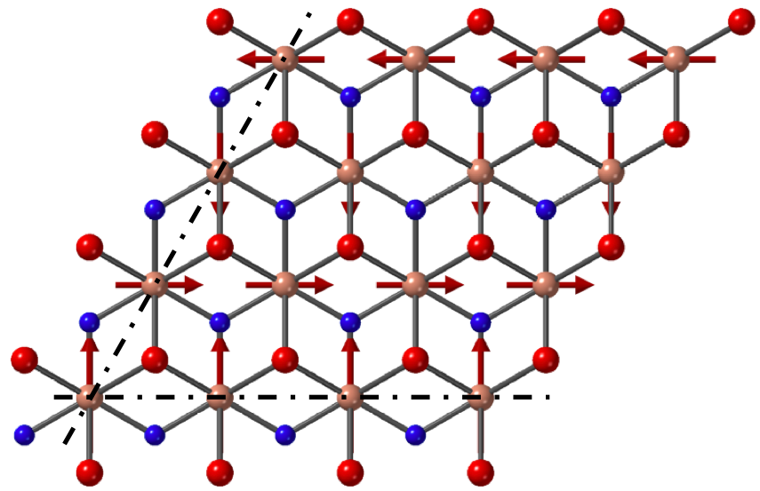
We complete this analysis by discussing the potential influence of the perpendicular Dzyaloshinskii-Moriya interaction of the stabilization of magnetic textures. It is clear that the large perpendicular magnetic anisotropy of Fe3GeTe2 (=1.3 meV/Fe) hinders the stabilization of Néel in-plane spin spirals. Nevertheless, for the sake of the discussion let us disregard the role of the magnetic anisotropy and only focus on the influence of the Dzyaloshinskii-Moriya interaction itself. What is particularly remarkable is that the antisymmetric dispersion is quite different from the dispersion obtained at, e.g., transition metal interfaces Ferriani2008 ; Kashid2014 ; Belabbes2016 . In the latter, the antisymmetric contribution of the dispersion has a large slope around , from which the long-wavelength Dzyaloshinskii-Moriya coefficient is usually extracted. In Fig. 3, the slope close to vanishes and the antisymmetric dispersion only takes off aways from the origin. This feature means that the Dzyaloshinskii-Moriya interaction has no impact in the long wavelength limit and is unlikely to stabilize large (10 nm) chiral textures. Nonetheless, it does tend to stabilize short-wavelength spin spirals. Indeed, the dispersion is peaked around . Considering that this dispersion is computed along the path, it means that Dzyaloshinskii-Moriya interaction tends to stabilize planar homochiral spin spirals propagating along a low symmetry direction of the Fe3GeTe2 crystal. Figure 5 shows such a planar spin spiral extended along the (100) direction of the crystal (dashed lines). The (100) direction is indeed characterized by broken mirror symmetry and therefore favors perpendicular Dzyaloshinskii-Moriya interaction, consistently with the analysis provided above.
Conclusion -
Using both symmetry arguments and first principle calculations, we have shown that the Dzyaloshinskii-Moriya interaction of Fe3GeTe2 adopts the form , with a Dzyaloshinskii-Moriya vector perpendicular to the (001) plane. This interaction is unable to stabilize the Néel skyrmions reported recently in thick Fe3GeTe2 layers, but it possesses remarkable characteristics. It vanishes in the long wavelength limit and only survives for small textures as it tends to stabilize planar spin spiral with wavevector and propagating along (100) direction, i.e., perpendicular to the (110) mirror plane direction. Nonetheless, in realistic situations, the large perpendicular magnetic anisotropy of Fe3GeTe2 monolayers prevents the formation of such planar spin spirals, at least in the monolayer limit. Cancelling this perpendicular anisotropy by surface engineering represents an appealing challenge both experimentally and theoretically as it could open avenues for the generation of unusual chiral textures.
Acknowledgements.
S.L. and A.M. thank G. Bihlmayer and S. Blügel for useful discussions. This work was supported by the King Abdullah University of Science and Technology (KAUST) through the Office of Sponsored Research (OSR) [Grant Number OSR-2017-CRG6-3390]. K.-W. K acknowledges support from the KIST institutional program and the National Research Foundation of Korea (2020R1C1C1012664)References
- (1) Huang et al., Nature 546, 270 (2017).
- (2) Bonilla et al., Nature Nanotechnology 13, 289 (2018).
- (3) Li et al., Advanced Materials 30, 1801043 (2018).
- (4) Sun et al., arXiV:1909.09797v1 (2019).
- (5) Deng et al., Nature 563, 94 (2018).
- (6) Li et al., ACS Applied Materials & Interfaces 11, 10729 (2019).
- (7) Zhang et al., Applied Physics Letters 116, 042402 (2020).
- (8) Park et al., Nano Letters 20, 95 (2020).
- (9) Alghamdi et al., Nano Letters 19, 4400 (2019).
- (10) X. Wang, J. Tang, X. Xia, C. He, J. Zhang, and Y. Liu, Science Advances 5, eaaw8904 (2019).
- (11) J. Xu, W. A. Phelan, and C.-l. Chien, Nano Letters 19, 8250 (2019).
- (12) Fang et al., Applied Physics Letters 115, 212402 (2019).
- (13) Z. Wang, D. Sapkota, T. Taniguchi, K. Watanabe, D. Mandrus, and A. F. Morpurgo, Nano Letters 18, 4303 (2018).
- (14) Albarakati et al., Science Advances 5, eaaw0409 (2019).
- (15) Wang et al., arXiv:1907.08382 (2019).
- (16) Ding et al., arXiv:1912.11228 (2019).
- (17) Park et al., arXiv:1907.01425 (2019).
- (18) I. Dzyaloshinskii, Soviet Physics JETP 5, 1259 (1957).
- (19) T. Moriya, Physical Review 120, 91 (1960).
- (20) N. Nagaosa and Y. Tokura, Nature nanotechnology 8, 899 (2013).
- (21) G. Chen, A. Mascaraque, A. T. N?Diaye, and A. K. Schmid, Applied Physics Letters 106, 242404 (2015).
- (22) O. Johansen, V. Risinggard, A. Sudbo, J. Linder, and A. Brataas, Physical Review Letters 122, 217203 (2019).
- (23) F. Freimuth,S. Blügel, and Y. Mokrousov, Journal of Physics: Condensed Matter 26, 104202 (2014).
- (24) Zelezny et al., Physical Review B 95, 014403 (2017).
- (25) A. Raeliarijaona, R. Nepal and A. A. Kovalev, Physical Review Materials 2, 124401 (2018).
- (26) K. M. D. Hals and K. Everschor-Sitte, Physical Review Letters 119, 127203 (2017).
- (27) S. Rohart and A. Thiaville, Physical Review B 88, 184422 (2013).
- (28) You et al., Physical Review B 100, 134441 (2019).
- (29) http://www.flapw.de
- (30) P. Kurz, F. Förster, L. Nordström, G. Bihlmayer, and S. Blügel, Physical Review B 69, 024415 (2004).
- (31) M. Heide, G. Bihlmayer, and S. Blügel, Physica B: Condensed Matter 404, 2678 (2009).
- (32) Ferriani et al., Physical Review Letters 101, 027201 (2008).
- (33) A. Belabbes, G. Bihlmayer, F. Bechstedt, S. Blügel, and A. Manchon, Physical Review Letters 117, 247202 (2016).
- (34) J. P. Perdew, K. Burke, and M. Ernzerhof, Physical Review Letters 77, 3865 (1996).
- (35) J. P. Perdew and A. Zunger, Physical Review B 23, 5048 (1981).
- (36) A. Belabbes, G. Bihlmayer, S. Blügel, and A. Manchon, Scientific Reports 6, 24634 (2016).
- (37) Kashid et al., Physical Review B 90, 054412 (2014).