On Delay-limited Average Rate of HARQ-based Predictor Antenna Systems
Abstract
Predictor antenna (PA) system is referred to as a system with two sets of antennas on the roof of a vehicle, where the PAs positioned in the front of the vehicle are used to predict the channel state observed by the receive antennas (RAs) that are aligned behind the PAs. In this work, we study the effect of spatial mismatch on the accuracy of channel state information estimation, and analyze the delay-constrained average rate of hybrid automatic repeat request (HARQ)-based PA systems. We consider variable-length incremental redundancy (INR) HARQ protocol, and derive a closed-form expression for the maximum average rate subject to a maximum delay constraint. Moreover, we study the effect of different parameters such as the vehicle speed, the antenna distance and the rate allocation on the system performance. The results indicate that, compared to the open-loop case, the delay-limited average rate is considerably improved with our proposed PA-HARQ scheme.
I Introduction
One of the main use cases of future wireless networks is vehicle communications. In such setups, channel state information at the transmitter side (CSIT) plays a key role in the system design and optimization schemes. However, due to the mobility of the users, the typical channel estimation methods may be inaccurate as the position of the transmit/receive antennas may change quickly. For this reason, the predictor antenna (PA) concept has been proposed and evaluated in, e.g., [1, 2, 3, 4, 5]. Here, the PA setup refers to as a system where two sets of antennas are deployed on the roof of a vehicle, and the PA(s) positioned at the front of the vehicle are used to predict the channel observed by the receive antennas that are positioned behind the PA(s).
Typical PA systems have two problems, namely, spatial mismatch and spectral efficiency, compared to a static multiple input multiple output (MIMO) system with as many antenna elements. Specifically, due to, e.g., speed change or feedback/processing delay, the RAs may not reach the same point as the PA when they receive data, leading to imperfect CSIT. This spatial mismatch problem has been studied in [2, 3, 4] where different techniques are applied to compensate for this effect. Moreover, while the PA is mainly used to improve the CSIT, using one of the antennas only for CSIT estimation may not be efficient, in terms of spectral efficiency. This becomes important especially when we remember that, with a PA setup on top of buses/trains, the PA should serve a large number of users inside the vehicle, e.g., watching videos. In such cases, we have a delay-limited system in which a certain number of information bits should be transferred within a limited period of time.
From another perspective, hybrid automatic repeat request (HARQ) is a well-known technique to improve the data transmission reliability and efficiency. The main idea of HARQ is to retransmit the message that experienced poor channel conditions, reducing the outage probability [6, 7]. As the PA system includes the feedback link, i.e., from the PA to the base station (BS), HARQ can be supported by the PA structure in high mobility scenarios. That is, the BS could potentially adjust the transmit rate/power to the RA based on the feedback from the PA. In this way, it is expected that such a joint implementation of the PA and the HARQ scheme can improve the system efficiency and reliability.
In this paper, we develop an HARQ-based scheme for delay-limited PA systems where we need to transfer a certain number of bits within a limited period of time. The goal is to maximize the delay-constrained average rate in the presence of imperfect CSIT. We model the spatial mismatch of the PA system as an equivalent non-central Chi-squared channel with known part from the PA-BS channel and uncertainties from spatial mismatch, and perform rate adaptation analysis. Particularly, using the incremental redundancy (INR) protocol and variable-length coding, we derive closed-form expressions for the maximum delay-limited average rate as well as for the optimal rate allocation. Finally, we evaluate the effect of different parameters such as transmission delay and the vehicle speed on the average rate.
As opposed to [1, 2], where numerical and test-bed based analysis are presented, in this work we model the PA system analytically, and design an HARQ-based PA scheme. Moreover, our problem setup is different from the ones in [3, 4, 5] because of the HARQ setup and variable-length coding. Finally, our discussions on the average rate of the HARQ-assisted PA systems with imperfect CSIT have not been presented before.
The analytical and simulation results show that, while an HARQ-assisted PA system leads to considerable performance improvement, compared to the open-loop case, the average rate is remarkably affected by the spatial mismatch and delay constraint. Moreover, while our proposed scheme provides the same CSIT accuracy as typical PA setups, it gives the chance to better utilize the PA setup and improve the average rate. Finally, for a broad range of vehicle speeds/delay constraints, the optimal average rate scales with signal-to-noise ratio (SNR) almost logarithmically.
II System Model
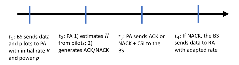
In the standard PA setup, proposed in [1, 2, 3, 4], the PA at the front of the vehicle111In the analysis, we consider a forward direction of the vehicle such that the front and the backward antennas work as the PA and the RA, respectively. With a reverse direction, the role of the antennas will be switched. is used only for channel estimation. As opposed, here, we develop a setup where the PA is used for both channel estimation and initial data transmission under frequency-division duplex (FDD). Our proposed setup and its timing can be seen in Figs. 1 and 2, respectively. Here, at the BS sends pilots as well as the encoded data with certain initial rate and power to the PA. Then, at , the PA estimates the BS-PA channel from the received pilots. At the same time, the PA tries decoding the data and generates an acknowledgement (ACK) if the decoding of the data is successful. Otherwise, a negative acknowledgement (NACK) will be fed back. ACK or NACK is sent to the BS at . In case of an NACK, the PA also sends CSIT feedback to the BS so that it gets an estimation of . Define . Based on the received feedback, the BS decides whether or not to retransmit the message with an adapted rate. Finally, at and with NACK, the BS sends data to the RA with an adapted rate. For simplicity of presentations, we assume the feedback link to be perfect. This is motivated by the fact that, compared to the direct BS-PA link, considerably lower rate is required in the feedback link. Finally, one can follow the same procedure as in [4] to model the quantization feedback error as an extra additive Gaussian noise.
In this way, the signals received by the PA and the RA in the first and second rounds are
| (1) |
and
| (2) |
respectively, where is the transmit power while and are the transmitted message with unit variance, and represents the independent and identically distributed (IID) complex Gaussian noise added at the receiver side. Also, represents the BS-RA channel coefficient. Note that, as explained in the following, the signals and may be of different lengths, as functions of the channel quality and maximum delay constraint.
We assume that the vehicle moves through a stationary electromagnetic standing wave pattern, and the system is moving in a straight line. Because of the short control-loop delay, the moving distance is in the order of centimeter so the moving direction is almost linear. This assumption has been experimentally verified in, e.g., [8]. Thus, if the RA reaches exactly the same position as the position of the PA when receiving the pilots, it will experience the same channel, i.e., , and the CSIT will be perfect. However, if the RA does not reach the same point as the PA, due to, e.g., the BS processing delay is not equal to the time that we need until the RA reaches the same point as the PA, the RA may receive the data in a place different from the one in which the PA was receiving the pilots. Such spatial mismatch may lead to CSIT inaccuracy, which affects the system performance considerably.
Let us define as the effective distance between the place where the PA estimates the channel at time , and the place where the RA reaches at time . Then, we have
| (3) |
where is the displacement of the vehicle during time interval , and is the velocity of the vehicle. Then, is the antenna separation between the PA and the RA. We assume to be known by the BS.
Using the classical Jake’s correlation model and assuming a semi-static propagation environment, i.e., assuming that the coherence time of the propagation environment is larger than , the channel coefficient of the BS-RA downlink can be modeled as [3, eq. (5)]
| (4) |
Here, which is independent of the known channel value , and spatial correlation factor is a function of the effective distance as
| (5) |
Furthermore, and , where is from Jake’s model
| (6) |
where has independent circularly-symmetric zero-mean complex Gaussian entries with unit variance, and is the channel correlation matrix with the -th entry
| (7) |
Here, represents the -th order Bessel function of the first kind. Moreover, denotes the carrier wavelength, i.e., where is the speed of light and is the carrier frequency. Note that if, instead of uniform Jake’s model, we consider different scattering models [9, Table 6.2] to study the effect of spatial correlation, (7) is changed to
| (8) |
for Gaussian scattering, and
| (9) |
for rectangular scattering (see Section IV for discussions).
From (4), for a given and , follows a Rician distribution. Let us define the channel gains between BS-PA and BS-RA as and , respectively. Then, the probability density function (PDF) of is given by
| (10) |
which is non-central Chi-squared distributed with the cumulative distribution function (CDF)
| (11) |
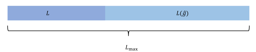
with being the Marcum-Q-function. As shown in Fig. 3, let us denote the maximum acceptable delay constraint by channel use. That is, gives the maximum acceptable delay, or the maximum possible coding length, for data transmission. We present the block length allocated to the first and the second transmission signals by and , respectively, with . Here, is optimized based on average performance, and is based on the instantaneous channel quality . This is because we do not have instantaneous CSIT in Round 1, and, therefore, we should send the data with a fixed rate which is determined based on all possible values of channel realization weighted by the channel distribution. However, in the second round, the sub-codeword length is adapted based on the instantaneous channel quality available at the BS. In the following, we optimize the average rate in the presence of variable-length coding and a maximum delay constraint.
III Analytical Results
Let us denote the initial rate by nats per channel use (npcu), where is the number of nats222Here, the results are presented in terms of nats, i.e., symbols. It is straightforward to represent the results in terms of bits by scaling the rate terms by . per codeword. Here, the results are presented for the cases with moderate/long codewords, which is of interest in moving relays [2]. In such cases, the error probability converges to the outage probability and we can follow the same information theoretical approach as in [6, 7] to analyze the system performance. Then, in the first transmission, if the instantaneous channel gain supports the rate, i.e., or equivalently, where , an ACK is sent back to the BS and the transmission stops. On the other hand, if , an NACK as well as the instantaneous channel gain are sent back to the BS. Then, in Round 2, we determine the required rate as
| (12) |
which is equivalent to
| (13) |
with being the length of the redundancy bits sent in the second round. Let us denote which is limited by the delay constraint . If , with , leading to , no signal is sent in the second round because the maximum delay constraint can not be satisfied. Otherwise, if , we send a sub-codeword with length . Note that, following the standard INR protocol [6, 7], in the retransmissions only redundancy bits are sent and one can follow the state-of-the-art variable-length coding schemes developed for INR, e.g., [7, 10], to generate them.
In this way, the average rate, for given , is obtained as
| (14) |
Here, is the indicator function and is the event that the message is decoded in the second round. Note that, with the rate allocation scheme of (12), it is straightforward to show that occurs if and only if . In this way, (14) can be rewritten as
| (15) |
Finally, averaging the system performance over all possible , we can obtain the average rate as follows.
Theorem 1.
The average rate of the proposed PA-HARQ scheme is approximately given by (III).
Proof.
Using (15) and taking average over , whose PDF is given by , we have
| (16) |
Here, is obtained by for small/moderate values of , using [11, Eq. (A-3-2)]
| (17) |
and [12, Eq. (9.7.1)]. Then, in we use linear approximation of at , with and . Moreover, is obtained by defining and as
| (18) |
and
| (19) |
with some manipulations. Here, represents the exponential integral, and is the error function. ∎
Using (III), the optimal average rate can be found as . Setting the derivative of (III) with respect to equal to zero, the optimal transmit rate is found by numerical solution of
| (20) |
which is a one-dimensional equation and can be solved effectively by, e.g., bisection method.
Finally, to evaluate the effectiveness of the proposed setup, we consider following benchmarks:
- •
-
•
Basic ARQ: Here, we follow the same method as in the proposed scheme, except that in the second round exactly the same signal is retransmitted and the receiver does not combine the two copies of the signal. Then, (15) is rephrased as
(22) and one can follow the same method as in Theorem 1 to derive the average system performance.
-
•
Diversity-based transmission: Here, we send the same signal in two spectrum resources simultaneously, and do maximum ratio combing (MRC) at the receiver. Then, the throughput is given by
(23)
IV Simulation Results
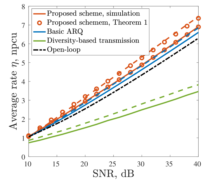
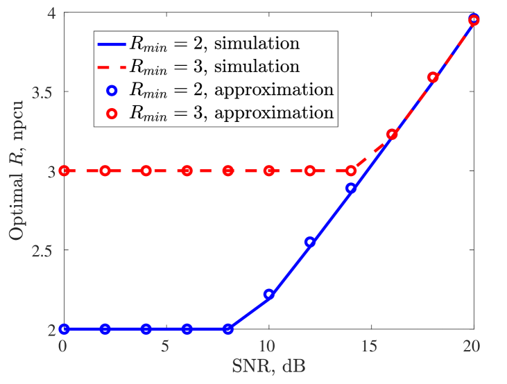
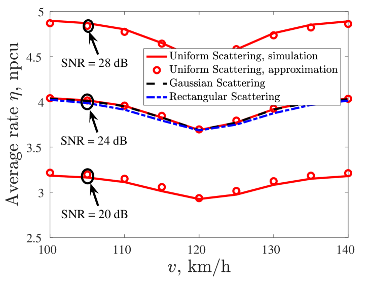
In the simulations, we set = 5 ms, carrier frequency = 2.68 GHz with being the carrier wavelength, and , which affect the spatial correlation factor as given in (5). In Fig. 4, we demonstrate the optimal average rate in npcu with different cases for a broad range of SNRs which, because the noise has unit variance, we define as . Here, we set npcu which corresponds to a delay constraint (cf. Sec. III), and . The approximation values are obtained by Theorem 1, and the results are compared with the benchmark schemes given in (21)-(23). Figure 5 presents optimal values of initial rate allocation for different values of as a function of the SNR. Here, we set npcu, and . Then, the optimal average rate as a function of the vehicle velocities is illustrated in Fig. 6, with npcu, and SNR = 20, 24, and 28 dB. Moreover, we present the approximation values from Theorem 1. Here, as explained in [3, Section II], manipulating is equivalent to changing the level of spatial correlation for given values of , and in (4). Finally, we study the effect of different scattering models on the system performance, i.e., uniform scattering (7), Gaussian scattering (8), and rectangular scattering (9).
According to the figures, we can conclude the following:
- •
- •
-
•
For a broad range of parameter settings and SNRs, the optimal rate increases with SNR, in the log domain, almost linearly (Fig. 5). As increases, i.e., with more stringent delay-constraint, higher initial transmission rate is required for the optimal average rate, as can be seen in the low-SNR range of the figure.
-
•
In Fig. 6, there is a minimum value for the average rate. This is intuitively because at low and high speeds, i.e., km/h and km/h, we have larger , which although it reduces the CSIT accuracy, provides higher average rate since it gives better spatial diversity. The lowest value of is observed at around 120 km/h, which matches our straightforward calculation from . Moreover, the effect of different scattering models on the system performance is relatively negligible (Fig. 6). Thus, the analytical and the simulation-based conclusions hold for different scattering models.
V Conclusion
We proposed an HARQ-based approach in order to compensate for the spatial mismatch and spectral under-utilization of PA systems. We designed the system such that the feedback from the PA can be used to adjust the codeword length in order to improve the average rate. The simulation and analytical results show that, while HARQ-assisted PA systems lead to considerable performance improvement, compared to different benchmark systems, the average rate is remarkably affected by the spatial mismatch, the SNR as well as the delay constraint.
References
- [1] M. Sternad, M. Grieger, R. Apelfröjd, T. Svensson, D. Aronsson, and A. B. Martinez, “Using predictor antennas for long-range prediction of fast fading for moving relays,” in Proc. IEEE WCNCW, Paris, France, Apr. 2012, pp. 253–257.
- [2] D.-T. Phan-Huy, M. Sternad, and T. Svensson, “Making 5G adaptive antennas work for very fast moving vehicles,” IEEE Intell. Transp. Syst. Mag., vol. 7, no. 2, pp. 71–84, Apr. 2015.
- [3] H. Guo, B. Makki, and T. Svensson, “Rate adaptation in predictor antenna systems,” IEEE Wireless Commun. Lett., vol. 9, no. 4, pp. 448–451, Apr. 2020.
- [4] H. Guo, B. Makki, M.-S. Alouini, and T. Svensson, “A semi-linear approximation of the first-order Marcum -function with application to predictor antenna systems,” Jan. 2020, available at: https://arxiv.org/abs/2001.09264.
- [5] ——, “Power allocation in HARQ-based predictor antenna systems,” Apr. 2020, available at https://arxiv.org/abs/2004.01421.
- [6] G. Caire and D. Tuninetti, “The throughput of hybrid-ARQ protocols for the Gaussian collision channel,” IEEE Trans. Inf. Theory, vol. 47, no. 5, pp. 1971–1988, Jul. 2001.
- [7] S. Sesia, G. Caire, and G. Vivier, “Incremental redundancy hybrid ARQ schemes based on low-density parity-check codes,” IEEE Trans. Commun., vol. 52, no. 8, pp. 1311–1321, Aug. 2004.
- [8] N. Jamaly, R. Apelfröjd, A. Belen Martinez, M. Grieger, T. Svensson, M. Sternad, and G. Fettweis, “Analysis and measurement of multiple antenna systems for fading channel prediction in moving relays,” in Proc. IEEE EuCAP, The Hague, The Netherlands, Apr. 2014, pp. 2015–2019.
- [9] A. Goldsmith, Wireless Communications. Cambridge University Press, 2005.
- [10] L. Ma, J. Xiong, and Y. Wei, “An incremental redundancy HARQ scheme for Polar code,” Aug. 2017, available at: https://arxiv.org/abs/1708.09679.
- [11] M. Schwartz, W. R. Bennett, and S. Stein, Communication Systems and Techniques. John Wiley & Sons, 1995.
- [12] M. S. Abramowitz and I. Stegun, “Handbook of Mathematical Functions with Formulas, Graphs, and Mathematical Tables,” New York: Dover, 1972.
- [13] R. M. Corless, G. H. Gonnet, D. E. Hare, D. J. Jeffrey, and D. E. Knuth, “On the Lambert function,” Advances in Computational Mathematics, vol. 5, no. 1, pp. 329–359, Dec. 1996.