Control of a filter cavity with coherent control sidebands
Abstract
For broadband quantum noise reduction of gravitational-wave detectors, frequency-dependent squeezed vacuum states realized using a filter cavity is a mature technique and will be implemented in Advanced LIGO and Advanced Virgo from the fourth observation run. To obtain the benefit of frequency-dependent squeezing, detuning and alignment of the filter cavity with respect to squeezed vacuum states must be controlled accurately. To this purpose, we suggest a new length and alignment control scheme, using coherent control sidebands which are already used to control the squeezing angle. Since both squeezed vacuum states and coherent control sidebands have the same mode matching conditions and almost the same frequency, detuning and alignment of the filter cavity can be controlled accurately with this scheme. In this paper, we show the principle of this scheme and its application to a gravitational-wave detector.
I Introduction
Gravitational waves (GW) were first detected by Advanced LIGO in 2015 Abbott et al. (2016) and since then many more GW observations have been performed by Advanced LIGO and Advanced Virgo Abbott et al. (2019). To increase the number of detections, the sensitivity of the detectors must be constantly improved. One of the main noise sources which limits the sensitivity of GW detectors is the so-called quantum noise. Quantum noise is divided into shot noise, which limits the sensitivity at high frequency and radiation pressure noise, which limits the sensitivity at low frequency. An effective way to reduce quantum noise is to inject squeezed vacuum states into the interferometer Caves (1981). The reduction of quantum noise with squeezing was realized for the first time at GEO600 Abadie et al. (2011), and it has been recently implemented also in Advanced LIGO and Advanced Virgo since the beginning of the third observation run (O3) Tse et al. (2019); Acernese et al. (2019). However, conventional frequency-independent phase squeezed vacuum states increases radiation pressure noise at low frequency while it reduces shot noise at high frequency. For broadband quantum noise reduction, frequency-dependent squeezing produced with a filter cavity is the most promising technique Kimble et al. (2001). Advanced LIGO and Advanced Virgo plan to implement frequency-dependent squeezing with 300 m filter cavities from the fourth observation run (O4) Abbott et al. . In order to achieve the frequency dependence below 100 Hz, the cavity has to be operated in a detuned configuration which means off resonance of the carrier and it needs a storage time of about 3 ms.
Demonstration of frequency-dependent squeezing below 100 Hz, necessary for broadband quantum noise reduction in GW detectors, has been recently achieved Zhao et al. (2020); McCuller et al. (2020).
One of main challenges in the production of frequency-dependent squeezing by using filter cavities is the length and alignment control of the filter cavity itself. In fact, since squeezing is a vacuum state with no coherent amplitude, it is not suitable to provide the error signals necessary for the control. The use of auxiliary fields is therefore needed. In previous experiments Zhao et al. (2020), the filter cavity was controlled with an auxiliary green field with a wavelength of 532 nm while the squeezed field is at the GW detector laser wavelength, 1064 nm. However, controlling length and alignment of the filter cavity with the green field does not ensure the alignment of squeezed field to the filter cavity, since the overlap of the green and squeezed field can drift. In addition, fluctuation of the relative phase delay between green and infrared field induced by anisotropies or temperature dependency of the cavity mirror coating can lead to a detuning fluctuation Macleod (2018). Another challenge of the filter cavity control with the green field is that phase/frequency noise on the green field creates real length noise in the filter cavity due to feedback control McCuller et al. (2020).
The squeezed field is produced by a parametric down-conversion process inside an optical parametric oscillator (OPO). The use of an auxiliary field, which resonates inside the OPO, ensures that it is perfectly spatially overlapped with the squeezed field. For the length control of the filter cavity, a recent work has successfully tested a scheme which uses an additional auxiliary field injected into the OPO with a small frequency offset with respect to the squeezed field McCuller et al. (2020).
In this paper, we suggest a new length and alignment control scheme whose error signal is provided by the so-called coherent control (CC) field. Such field is included in all the squeezed vacuum sources for GW detectors and it is used to control the squeezing angle Chelkowski et al. (2007). Since the coherent control sidebands (CCSB) are produced inside the OPO together with the squeezed vacuum states, they have the same mode matching conditions and almost the same frequency. The relative frequency of carrier and CCSB can be controlled accurately with a frequency offset phase locked loop and can be tuned so that carrier is properly detuned. Such difference is only a few MHz which makes any possible effect due to the coating negligible. Therefore, length and alignment control with CCSB ensure proper detuning and alignment of the squeezed vacuum states to the filter cavity.
This paper is organized as follows: in section II.1 and II.2, the error signal for the length and alignment control of the filter cavity are theoretically derived. In section II.3, the application of such control scheme to a GW detector is presented. In section II.4, the coupling between the coherent control loop and the filter cavity length control loop is studied. In section II.5, reshaping of frequency-dependent phase noise and an updated squeezing degradation budget with this control scheme are presented. In section III, the computation of noise requirements to ensure the feasibility of such technique is presented.
II Principle
II.1 Filter cavity length signal
When coherent control field, which is detuned by with respect to carrier frequency , is injected into OPO, a sideband which is detuned by is generated by the pump field whose frequency is 2 Chelkowski et al. (2007). The coherent control field passing through OPO can be written as Oelker (2016)
| (1) | |||||
where is the amplitude of the coherent control field without the pump field, is the OPO nonlinear factor and , are the common and relative phase of the coherent control field and its sideband generated by OPO respectively. Note that (1) assumes that is much lower than the OPO bandwidth , . The OPO nonlinear factor can be written as
| (2) |
where is the power of the pump field, is the OPO threshold power, and is the nonlinear gain. and are determined by the amplitude and phase of the pump field, respectively. The nonlinear gain is related to the generated squeezing without losses as follows Oelker (2016):
| (3) |
and are controlled by the coherent control loops to control the squeezing angle. The squeezing angle is the relative phase between the local oscillator and the average of CCSB and can be written as
| (4) |
where is the phase of the local oscillator (LO). There are two coherent control loops (we call them CC1 and CC2 in this paper) and is kept constant by CC1 and the relative phase between LO and CC is kept constant by CC2 to make the squeezing angle constant. In this paper, we assume that is kept 0, but has residual noise around 0, .
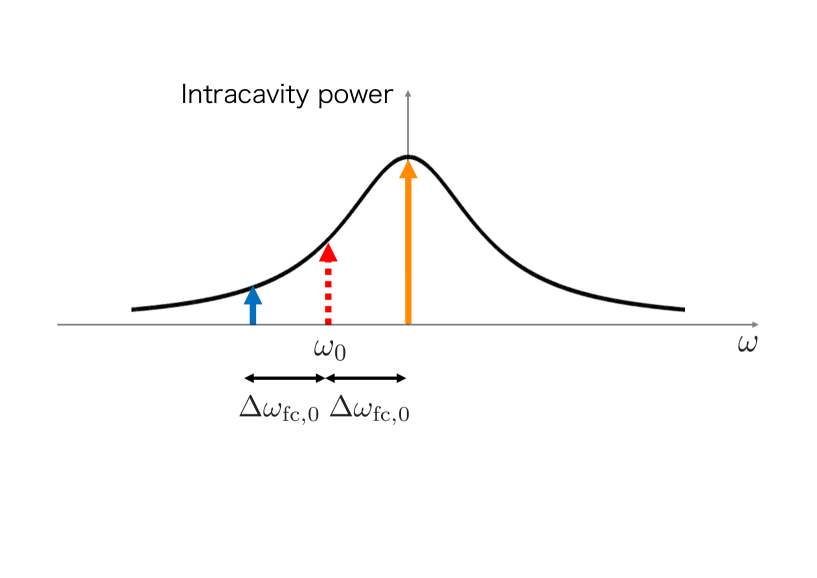
To obtain frequency-dependent squeezing from a filter cavity, the resonance of the filter cavity must be detuned properly from the carrier. By choosing the frequency of coherent control field () as follows, the coherent control field can be resonant inside the filter cavity while the resonance of the filter cavity is properly detuned from the carrier (FIG. 1):
| (5) |
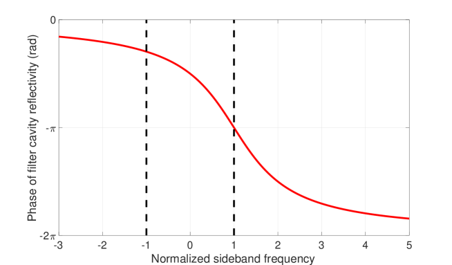
where is an integer number, is the free spectral range of the filter cavity, is the filter cavity length and is the optimal filter cavity detuning with respect to carrier. In this condition, the coherent control sideband at is detuned by with respect to the filter cavity resonance and so almost reflected by the filter cavity. The phase of the filter cavity reflectivity is shown in FIG. 2. Since the phase of filter cavity reflectivity for the coherent control field which is on resonance is sensitive to the detuning fluctuation compared with the other sideband which is off resonance, the filter cavity length signal can be obtained by detecting the beat note of CCSB.
The coherent control sidebands reflected by the filter cavity is
| (6) | |||||
where is
| (7) |
and is the complex reflectivity of the filter cavity and can be written as Kwee et al. (2014)
| (8) |
where
| (9) | |||||
| (10) |
with the filter cavity half-bandwidth and the filter cavity round trip losses. is a variable which represents the actual filter cavity detuning. Note that the approximation in (8) holds for a high finesse cavity near the resonance, and where is the sideband frequency and is the filter cavity input transmissivity.
Amplitude and phase of the filter cavity reflectivity for CCSB can be written as
| (11) | |||||
| (12) | |||||
Filter cavity length signal can be obtained by detecting the beat note of the CCSB:
Demodulating this signal by (In-phase) and (Quadrature) and low-passing it, filter cavity length signal as a function of the filter cavity detuning is
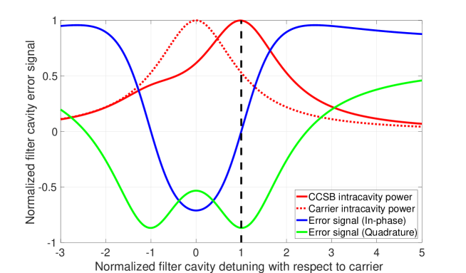
The relative phase noise of CCSB is a noise source for the filter cavity length signal. When , the filter cavity length signal (LABEL:I_phase), (LABEL:Q_phase) normalized with respect to is shown in FIG. 3. The parameters used in this calculation are shown in TABLE 1.
| Parameter | Symbol | Value |
|---|---|---|
| Filter cavity length | 300 m | |
| Filter cavity half-bandwidth | Hz | |
| Filter cavity detuning | Hz | |
| Filter cavity finesse | 4360 | |
| Filter cavity input mirror transmissivity | 0.00136 | |
| Filter cavity round trip losses | 80 ppm | |
| Injection losses | 5 | |
| Readout losses | 5 | |
| Mode-mismatch losses | 2 | |
| (squeezer-filter cavity) | ||
| Mode-mismatch losses | 5 | |
| (squeezer-local oscillator) | ||
| Frequency-independent phase | 30 mrad | |
| noise (rms) | ||
| Filter cavity length noise (rms) | 1 pm | |
| Generated squeezing | 9 dB | |
| Nonlinear gain | 3.6 |
Filter cavity length noise causes detuning noise as follows,
| (16) |
When , phase response of the filter cavity reflectivity to the detuning noise can be calculated from (12),
| (17) | |||||
where , is wavelength of carrier, and is filter cavity finesse. Here we assumed , which is true for parameters shown in TABLE 1. The filter cavity length signal (In-phase) (LABEL:I_phase) is
| (18) | |||||
Since the relative phase noise of CCSB can be stabilized by CC1 below 1.7 mrad Vahlbruch et al. (2016), the residual filter cavity length signal (18) can be obtained with a good enough SNR. Phase noise of an RF source for the demodulation also becomes a noise source for the filter cavity length signal. Typical phase noise of an RF source for the demodulation is several tens of rad and much smaller than (18).
II.2 Filter cavity alignment signal
Coherent control sidebands can be also used to control the alignment of the filter cavity by wavefront sensing Morrison et al. (1994).
Misalignment of the filter cavity axis with respect to input beam axis and misalignment of immediately reflected beam axis with respect to the filter cavity axis can be represented in terms of dimensionless coupling factors as follows:
| (19) | |||||
| (20) |
where is the beam radius at the waist position and is the beam divergence. and represent the transverse displacement in axis direction measured at the waist position of the filter cavity axis with respect to the input beam axis and the immediately reflected beam axis with respect to the filter cavity axis, respectively. represent the tilt around axis of the filter cavity axis with respect to the input beam axis and the immediately reflected beam axis with respect to the filter cavity axis, respectively. Here, axis is the beam axis and axis is orthogonal to the axis. is the beam waist position. can be written in terms of input, end mirror misalignment of the filter cavity as follows:
| (21) | |||||
| (22) | |||||
where is the radius of curvature of the input and end mirrors, and are angular misalignment of input and end mirrors. The direction of the input and end mirror misalignment is defined so that the positive direction of the misalignment causes the displacement of filter cavity axis in positive direction of axis.
We only treat -axis misalignment (Hermite-Gaussian [HG] 10 mode) and calculations of -axis misalignment (HG 01 mode) are entirely analogous.
The wavefront sensing (WFS) signal can be written as (see Appendix A)
| (23) | |||||
where and is the gouy phase. Demodulating (23) by (In-phase) and low-passing it, first term of (23), which is proportional to filter cavity length signal, will disappear.
WFS signal after the demodulation is
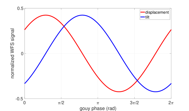
| (24) | |||||
WFS signal is shown in FIG. 4. Displacement and tilt signal of the filter cavity can be obtained with two different gouy phases.
The fourth term in (83) is beat note of CCSB HG10 mode and becomes a noise source for the filter cavity length signal when misalignment of the filter cavity fluctuates. In order not to spoil the filter cavity length signal (18), the requirement of maximum rms angular motion of filter cavity mirrors should be rad (see Appendix A) and this is achievable by double pendulum suspensions in KAGRA Kokeyama et al. (2018). By numerically calculating as functions of input, end mirror misalignment, this requirement corresponds to . Since this requirement is more stringent than the requirement of mode-mismatch losses (squeezer-filter cavity) which is 2 , we set the requirement of as .
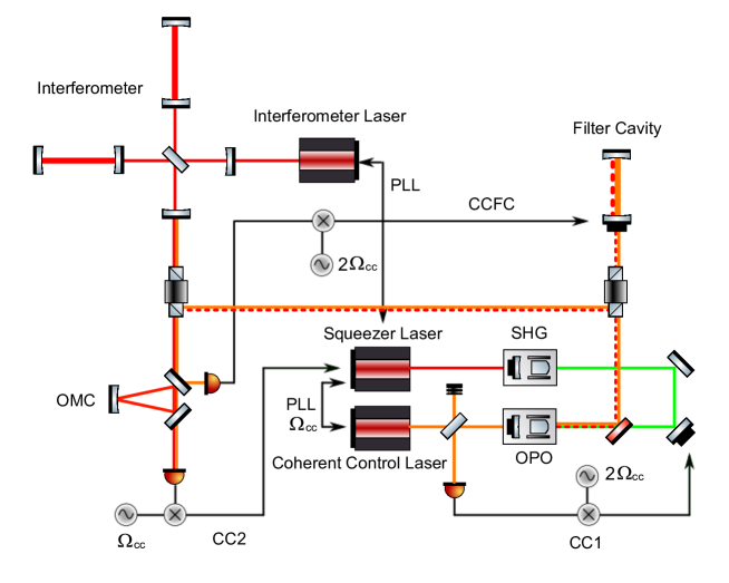
II.3 Experimental setup
An example of experimental setup when this scheme is implemented in GW detectors is shown in FIG. 5. There are three control loops which are CC1, CC2, and the filter cavity control loop with CCSB (we call it CCFC in this paper).
CCFC error signal can be obtained at output mode cleaner (OMC) reflection since CCSB are almost fully reflected by OMC while carrier almost transmits through OMC. The error signal is demodulated by 2 and fed back to the filter cavity length. The demodulation phase can be determined by injecting bright carrier field to the filter cavity and checking the carrier transmission and CCFC error signal at the same time as shown in FIG. 3. Fine tuning of the demodulation phase can be done by optimizing GW sensitivity. CC1 error signal to control the relative phase between the green field injected into OPO and the coherent control field can be obtained at OPO reflection and fed back to the green field path length. CC2 error signal to control the relative phase between the carrier and the coherent control field is obtained at OMC transmission and fed back to phase locked loop (PLL) between interferometer laser and squeezer laser Dooley et al. (2015).
II.4 Coherent control error signal
Since either of CCSB enters the filter cavity and senses the filter cavity length noise, the filter cavity length noise appears in CC2 loop which controls the relative phase between CCSB and LO. In the case of GW detectors, the LO is the interferometer laser. In this section, we will calculate the CC2 error signal which includes the phase noise from the filter cavity. For simplicity, here we write , and .
Signal at OMC transmission is
| (25) | |||||
where is the amplitude of LO and is the transmissivity of CCSB from OPO to OMC transmission.
Demodulating (25) by and low-passing it, where demodulation phase is
| (26) |
we find
| (27) | |||||
where
| (28) | |||||
| (29) |
When the squeezing angle is different from (squeeze quadrature) by , (4) can be written as
| (30) |
Assuming , CC2 error signal (27) can be written as
| (31) | |||||
where is the unbalance of the amplitude of CCSB and is the unbalance of the filter cavity reflectivity of CCSB. is
| (32) |
The first term in (31) is the constant offset, the second term is the relative phase noise between CC and LO which does not include the phase noise coming from the filter cavity (frequency-independent phase noise), the third term is the phase noise of CCSB coming from the filter cavity length noise (frequency-dependent phase noise at the detuning frequency) and the fourth term is the phase noise coming from the relative phase noise of CCSB. The constant offset in (31) should be removed to obtain . is the coupling from the CCFC loop which reshapes frequency-dependent phase noise as explained in the following section.
II.5 Reshaping of frequency-dependent phase noise
The CC2 error signal calculated in Sec. II.4 reshapes frequency-dependent phase noise which comes from the filter cavity length noise. This is caused by the coupling between CCFC loop and CC2 loop as shown in FIG. 6.
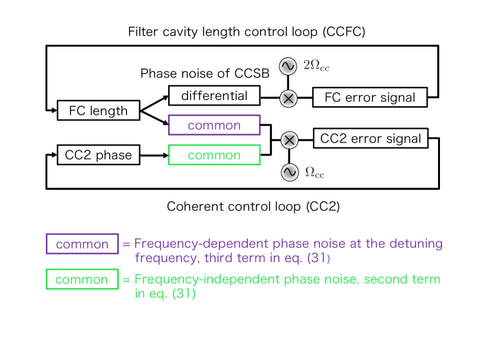
The fluctuation of the filter cavity length causes both differential and common phase noise of CCSB. The differential phase noise of CCSB is the CCFC error signal while the common phase noise of CCSB is frequency-dependent phase noise at the detuning frequency, which is the second term in (31). This frequency-dependent phase noise at the detuning frequency couples to the CC2 loop and is suppressed by the feedback loop while the frequency-dependent phase noise is increased at high frequency. In this section, we will explain the detail calculation of the frequency-dependent phase noise with feedback of CC2 loop.
Calculation of frequency-dependent phase noise is described in Kwee et al. (2014) and the calculation of this section will use the same formalism. For more details of the computation, see Appendix B.
Assuming multiple incoherent noise parameters in quantum noise have small Gaussian-distributed fluctuations with variance , the average readout noise is given by
| (33) |
For frequency-independent phase noise, which is the injection squeezing angle. For the frequency-dependent phase noise, which is the filter cavity detuning.
First we will explain about the calculation of frequency-independent phase noise which is necessary in order to calculate frequency-dependent phase noise with feedback from CC2 loop. The transfer matrix of the squeezer can be written as a function of injection squeezing angle ,
| (36) |
where R is a rotation matrix and is injection squeezing level. Frequency-independent phase noise can be represented by variations of injection squeezing angle, .
To calculate the effect of phase noise only, we restrict our discussion to an optimally matched filter cavity and no injection, readout losses. Noise due to vacuum fluctuations passing through the squeezer, can be written as (see Appendix B)
| (37) | |||||
| (38) | |||||
| (39) | |||||
| (40) | |||||
where
| (41) | |||||
is sideband frequency and was fixed to in Sections II.1-II.4. is the optomechanical coupling factor of the interferometer,
| (42) |
where is approximately the frequency at which quantum noise reaches the standard quantum limit and is the interferometer bandwidth. In the case of KAGRA, Hz, Hz Capocasa et al. (2016). When , and this represents the quantum noise of an optimally matched filter cavity with no injection and readout losses, (44) in Kwee et al. (2014).
From (33), frequency-independent phase noise of can be calculated as
Frequency-dependent phase noise can be calculated by averaging and . However, when there is detuning noise, there is also feedback from CC2 loop (32). As shown in FIG. 5, this feedback from CC2 loop is sent to the squeezer laser and changes the injection squeezing angle . Therefore, the frequency-dependent phase noise of with feedback from CC2 loop can be calculated as
Note that frequency-dependent phase noise is small above cavity pole of the filter cavity 57 Hz and we assumed that the gain of the CC2 loop below 57 Hz is large enough so that the feedback of the CC2 loop is perfect.
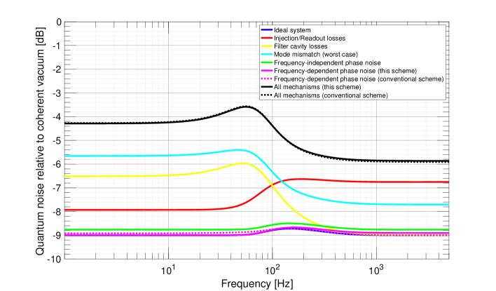
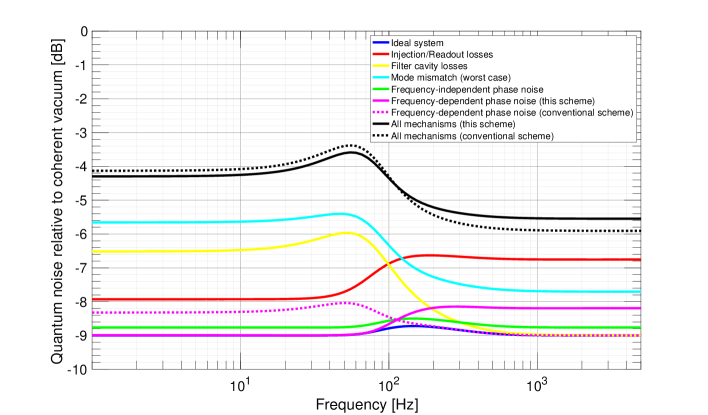
FIG. 7 and 8 show quantum noise relative to coherent vacuum with filter cavity length noise pm and 3 pm. The frequency-dependent phase noise with this scheme and with conventional scheme is shown as purple line and dotted purple line which are almost overlapping in FIG. 7. Parameters used in this calculation are shown in TABLE 1. The unbalance of the filter cavity relfectivity of CCSB is and the unbalance of the amplitude of CCSB is (). As shown in FIG. 7, frequency-dependent phase noise with this scheme and conventional scheme is small and almost the same with pm. However, as shown in FIG. 8, frequency-dependent phase noise with this scheme is suppressed at low frequency by the feedback from CC2 loop while it is increased at high frequency.
Effective phase noise at high frequency with feedback from CC2 loop in (LABEL:FD_phase_noise_with_CC) can be calculated from (17) and (32),
| (45) | |||||
The squeezing angle is affected by misalignment of LO and CC. The squeezing angle fluctuation at OMC transmission including the misalignment of LO and CC can be written as Oelker et al. (2014)
| (46) |
where is the attenuation factor of higher order modes by OMC and are relative amplitude of CC and LO TEM mode with respect to TEM 00 mode. and are relative phase of CC and LO TEM mode with respect to TEM 00 mode. Considering only HG10/01 mode and assuming that for , the squeezing angle fluctuation will be rad and it is small enough compared with frequency-independent/dependent phase noise. The misalignment of CCSB also affects the CCFC loop and this effect is calculated in Appendix A.
III Noise Calculation
The requirement of length control of the filter cavity is pm and the requirement of alignment control of the filter cavity is . In this section, we show that shot noise and PLL noise satisfy these requirements. We also show that backscattering noise of leaked carrier from the interferometer to the filter cavity does not spoil the quantum noise above 10 Hz where the quantum noise limits the GW sensitivity.
III.1 Shot noise
III.1.1 Shot noise for length control
We assume that the power of the coherent control field after OPO is uW and the power of the lower coherent control sideband is uW. When the filter cavity length signal is obtained at OMC reflection, junk light at OMC reflection including higher order modes and other RF sidebands contributes to the shot noise.
Shot noise of CCSB and the junk light at OMC reflection is given by
| (47) |
Here we assumed that frequencies of carrier, CCSB and junk light are almost the same and . This shot noise within the filter cavity control bandwidth becomes the filter cavity length noise by the control loop. This shot noise is the most fundamental limit of the filter cavity length signal SNR. From (18), we can compute the maximum power of this junk light at OMC reflection which allows not to spoil the filter cavity length signal as follows,
| (48) |
where is filter cavity length control bandwidth and set by requirement of backscattering noise McCuller and Barsotti (2020). According to (LABEL:junk_light), using parameters in TABLE 1, W in order not to spoil the filter cavity length signal and this requirement can be satisfied Somiya et al. (2019).
III.1.2 Shot noise for alignment control
We consider only shot noise of displacement signal of the filter cavity and the calculation of tilt signal is entirely analogous. From (24), we can compute the maximum power of junk light at OMC reflection which allows not to spoil the filter cavity alignment signal as follows:
| (50) |
| (51) | |||||
where is the maximum amplitude of the normalized WFS signal in FIG. 4 and is filter cavity alignment control bandwidth. According to (51), W in order not to spoil the filter cavity alignment signal and this requirement also can be satisfied.
III.2 Backscattering noise
The backscatteting noise comes from the leaked carrier from the interferometer to the filter cavity. The leaked carrier is injected to the filter cavity and scattered by the filter cavity length noise and reinjected into the interferometer. This backscattering noise must be below the vacuum fluctuation in order not to spoil the quantum noise of the interferometer McCuller and Barsotti (2020). Considering also the safety factor () and squeezing enhancement factor ( for 6 dB of quantum noise enhancement),
| (52) | |||||
| (53) | |||||
where is phase response of carrier to the filter cavity length noise (17) and is power of the leaked carrier from the interferometer to the filter cavity. We assumed that m above 10 Hz which can be realized in Advanced LIGO McCuller and Barsotti (2020). Given that the carrier output from the interferometer mW in advanced LIGO McCuller and Barsotti (2020), 81 dB of isolation factor from faraday isolators is required. There is a faraday isolator with more than 40 dB of isolation factor and with less than 1 of loss Genin et al. (2018). By using the 2 faraday isolators, more than 80 dB of isolation factor can be realized with less than 2 of loss and the backscattering noise can satisfy the requirement.
III.3 PLL noise
The PLL which controls the relative phase between the squeezer laser and the coherent control laser can cause detuning noise. The PLL frequency noise reflected by the filter cavity can be written as
| (54) |
where filter cavity half bandwidth is Hz and PLL phase noise is within PLL control bandwidth 40 kHz. The PLL phase noise has been chosen so to have rms of PLL phase noise mrad. The rms of PLL frequency noise within the filter cavity control bandwidth is
| (55) | |||||
The rms of PLL frequency noise is mHz.
This corresponds to rms of the filter cavity length noise m which satisfies the requirement.
IV Conclusion
We suggest a new length and alignment control scheme of a filter cavity with coherent control sidebands which are already used to control squeezing angle. It assures accurate detuning and alignment of the filter cavity with respect to squeezed vacuum states. It is shown that coherent control loop reshapes frequency-dependent phase noise with this scheme. The frequency-dependent phase noise at low frequency is suppressed by feedback from the coherent control loop while it is increased at high frequency. We also showed that shot noise and PLL noise with this scheme satisfy the requirement of length and alignment control of the filter cavity and backscattering noise of leaked carrier from the interferometer to the filter cavity does not spoil the quantum noise above 10 Hz where the quantum noise limits the GW sensitivity.
Acknowledgements.
This work was supported by JSPS Grant-in-Aid for Scientific Research (Grants No. 18H01224, No. 18H01235 and No. 18K18763) and JST CREST (Grant No. JPMJCR1873). We thank Kentaro Komori and Keiko Kokeyama for fruitful discussions.Appendix A Calculation of wavefront sensing
Input beam which includes HG 10 mode can be written as
| (59) |
where are the amplitude of HG 00, 10 mode and are normalized Hermite-Gaussian modes and can be written as Kogelnik and Li (1966),
| (60) | |||||
| (61) |
where is the first order Hermite polynomial, is the beam radius, is the gouy phase, is the beam radius of curvature and can be written as
| (62) | |||||
| (63) | |||||
| (64) | |||||
| (65) |
Filter cavity mode which is displaced in axis by and tilted around axis by with respect to input beam can be written as Morrison et al. (1994)
| (69) | |||||
| (72) |
where is (19) and first order of is considered.
Reflection matrix of an optimally aligned filter cavity is
| (75) |
where are, respectively, the filter cavity reflectivity of HG 00 and 10 mode of the coherent control field which is on resonance. Reflection matrix of a misaligned filter cavity in the first order of can be written as
| (78) | |||||
Assuming that for input beam, reflection beam from the misaligned filter cavity can be written as
| (80) |
We define and as
| (81) | |||||
| (82) |
where are, respectively, the filter cavity reflectivity of HG 00 and 10 mode of the coherent control sideband which is off resonance. From (80) to (82), term of the filter cavity error signal (LABEL:error_signal) can be written as
| (83) | |||||
WFS signal is given by the sum of the second and third terms of (83). Defining ,
| (84) | |||||
Differential signal of in -axis direction with a quadrant photo diode is
| (85) |
Since
and due to gouy phase separation in the cavity, WFS signal can be written as (23).
The fourth term in (83) is a noise source of the filter cavity length signal which is the first term in (83). The fourth term in (83) is
| (87) | |||||
Demodulating by , the first term in (87) which is proportional to the filter cavity length signal will disappear. After integration by , (87) will be
| (88) | |||||
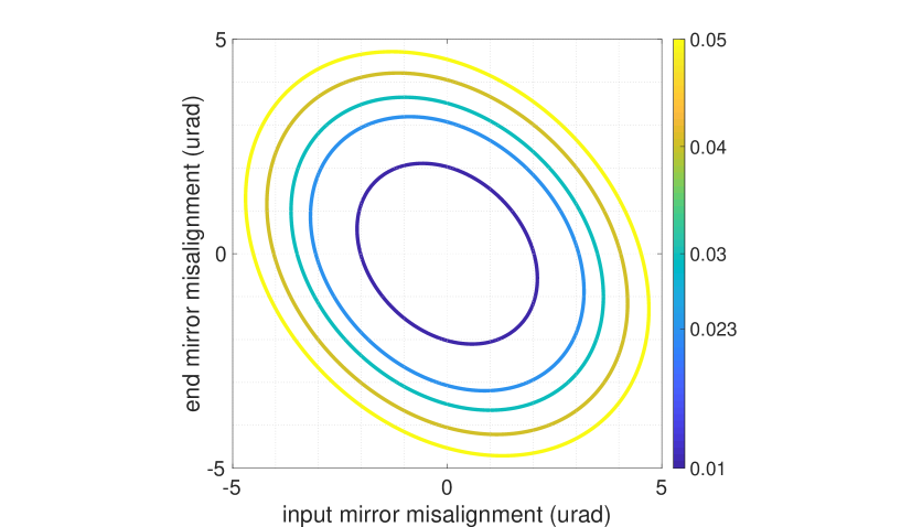
where we used . From (21) and (22), (88) can be numerically calculated in terms of input, end mirror misalignment as shown in FIG. 9. Here we assumed that m and cm Capocasa et al. (2018). (88) normalized with should be smaller than the residual filter cavity length signal normalized with which is mrad. Note that the filter cavity length signal in (18) is normalized with . We consider the maximum angular motion of the filter cavity mirrors as which corresponds to a circle with radius in FIG. 9. This circle should be smaller than the ellipse corresponding to 0.023. can be determined from the semi-minor axis of the ellipse corresponding to 0.023 in FIG. 9, and we obtain the requirement of as rad.
Appendix B Calculation of quantum noise
Calculation of quantum noise in this appendix is based on Kwee et al. (2014). Quantum noise can be divided into three parts, noise due to vacuum fluctuations passing through the squeezer , noise due to vacuum fluctuations which do not pass through squeezer , noise due to vacuum fluctuations in the readout .
Quantum noise at the interferometer readout is given by
| (89) | |||||
where () is vacuum fluctuation and I is identity matrix. is local oscillator and is the quantum noise in the quadrature containing the interferometer signal.
is written as
| (90) | |||||
| (93) | |||||
| (94) | |||||
| (95) | |||||
| (98) |
where , , are transfer matrices of interferometer, optimally matched filter cavity, and injection field, respectively. , are mode matching and mode mismatch matrix.
, is injection, readout transmissivity and can be written as
| (99) | |||||
| (100) |
where , are injection, readout losses.
, can be written as , where are complex coefficients when we express the squeezed vacuum states and the local oscillator in the basis of the filter cavity mode and can be written as
| (101) | |||||
| (102) |
where are the orthogonal basis of spatial modes and is the filter cavity fundamental mode.
is written as
| (103) | |||||
| (104) | |||||
| (105) |
is written as
| (106) |
Quantum noise normalized with respect to shot noise level used in Sec. II.5 is
| (107) |
For calculation of frequency-dependent phase noise, we can consider only since frequency-dependent phase noise of is negligible compared with and is independent of the filter cavity. From (89)-(100) and (107), (37) can be derived.
References
- Abbott et al. (2016) B. P. Abbott et al. (LIGO Scientific Collaboration and Virgo Collaboration), Phys. Rev. Lett. 116, 061102 (2016).
- Abbott et al. (2019) B. P. Abbott et al. (LIGO Scientific Collaboration and Virgo Collaboration), Phys. Rev. X 9, 031040 (2019).
- Caves (1981) C. M. Caves, Phys. Rev. D 23, 1693 (1981).
- Abadie et al. (2011) J. Abadie et al. (LIGO Scientific Collaboration), Nat. Phys. 7, 962 (2011).
- Tse et al. (2019) M. Tse et al., Phys. Rev. Lett. 123, 231107 (2019).
- Acernese et al. (2019) F. Acernese et al. (Virgo Collaboration), Phys. Rev. Lett. 123, 231108 (2019).
- Kimble et al. (2001) H. J. Kimble, Y. Levin, A. B. Matsko, K. S. Thorne, and S. P. Vyatchanin, Phys. Rev. D 65, 022002 (2001).
- (8) B. P. Abbott et al. (LIGO Scientific Collaboration, Virgo Collaboration and KAGRA Collaboration), arXiv: 1304.0670 [gr-qc] .
- Zhao et al. (2020) Y. Zhao et al., Phys. Rev. Lett. 124, 171101 (2020).
- McCuller et al. (2020) L. McCuller et al., Phys. Rev. Lett. 124, 171102 (2020).
- Macleod (2018) H. A. Macleod, Thin-Film Optical Filters, 5th ed. (CRC Press, Boca Raton, Florida, 2018).
- Chelkowski et al. (2007) S. Chelkowski, H. Vahlbruch, K. Danzmann, and R. Schnabel, Phys. Rev. A 75, 043814 (2007).
- Oelker (2016) E. Oelker, Ph.D. thesis, Massachusetts Institute of Technology (2016).
- Kwee et al. (2014) P. Kwee, J. Miller, T. Isogai, L. Barsotti, and M. Evans, Phys. Rev. D 90, 062006 (2014).
- Capocasa et al. (2016) E. Capocasa, M. Barsuglia, J. Degallaix, L. Pinard, N. Straniero, R. Schnabel, K. Somiya, Y. Aso, D. Tatsumi, and R. Flaminio, Phys. Rev. D 93, 082004 (2016).
- Vahlbruch et al. (2016) H. Vahlbruch, M. Mehmet, K. Danzmann, and R. Schnabel, Phys. Rev. Lett. 117, 110801 (2016).
- Morrison et al. (1994) E. Morrison, B. J. Meers, D. I. Robertson, and H. Ward, Appl. Opt. 33, 5041 (1994).
- Kokeyama et al. (2018) K. Kokeyama, J. G. Park, K. Cho, S. Kirii, T. Akutsu, M. Nakano, S. Kambara, K. Hasegawa, N. Ohishi, K. Doi, and S. Kawamura, Physics Letters A 382, 1950 (2018).
- Dooley et al. (2015) K. L. Dooley, E. Schreiber, H. Vahlbruch, C. Affeldt, J. R. Leong, H. Wittel, and H. Grote, Opt. Express 23, 8235 (2015).
- Oelker et al. (2014) E. Oelker, L. Barsotti, S. Dwyer, D. Sigg, and N. Mavalvala, Opt. Express 22, 21106 (2014).
- McCuller and Barsotti (2020) L. McCuller and L. Barsotti, LIGO-T1800447 (2020).
- Somiya et al. (2019) K. Somiya, E. Hirose, and Y. Michimura, Phys. Rev. D 100, 082005 (2019).
- Genin et al. (2018) E. Genin, M. Mantovani, G. Pillant, C. D. Rossi, L. Pinard, C. Michel, M. Gosselin, and J. Casanueva, Appl. Opt. 57, 9705 (2018).
- Kogelnik and Li (1966) H. Kogelnik and T. Li, Appl. Opt. 5, 1550 (1966).
- Capocasa et al. (2018) E. Capocasa, Y. Guo, M. Eisenmann, Y. Zhao, A. Tomura, K. Arai, Y. Aso, M. Marchiò, L. Pinard, P. Prat, K. Somiya, R. Schnabel, M. Tacca, R. Takahashi, D. Tatsumi, M. Leonardi, M. Barsuglia, and R. Flaminio, Phys. Rev. D 98, 022010 (2018).