Effects of oblique incidence and colliding pulses on laser-driven proton acceleration from relativistically transparent ultrathin targets
Abstract
The use of ultrathin solid foils offers optimal conditions for accelerating protons from laser-matter interactions. When the target is thin enough that relativistic self-induced transparency (RSIT) sets in, all of the target electrons get heated to high energies by the laser, which maximizes the accelerating electric field and therefore the final ion energy. In this work, we first investigate how ion acceleration by ultraintense femtosecond laser pulses in transparent CH2 solid foils is modified when turning from normal to oblique () incidence. Due to stronger electron heating, we find that higher proton energies can be obtained at oblique incidence but in thinner optimum targets. We then show that proton acceleration can be further improved by splitting the laser pulse into two half-pulses focused at opposite incidence angles. An increase by in the maximum proton energy and by a factor of in the high-energy proton charge is reported compared to the reference case of a single normally incident pulse.
1 Introduction
Laser-driven proton acceleration using ultraintense pulses has been an active field of research in the past two decades (Tikhonchuk, 2010; Daido et al., 2012; Macchi et al., 2013). The strong electric fields produced in the interaction of the ultraintense laser pulse with solid targets can accelerate protons to high energies on acceleration distances of only a few microns. This has led to the development on small-scale facilities of a large variety of applications, such as radiography (Romagnani et al., 2005), generation on warm dense matter (Patel et al., 2003; Pelka et al., 2010), inertial confinement fusion (Roth et al., 2001), nuclear physics (McKenna et al., 2003), or proton therapy (Bulanov & Khoroshkov, 2002). The most investigated, and routinely exploited mechanism is the so-called target normal sheath acceleration (TNSA), which benefits from a relatively easy implementation (Wilks et al., 2001; Clark et al., 2000; Maksimchuk et al., 2000; Snavely et al., 2000). TNSA, however, yields maximum ion energies that scale rather weakly with the laser intensity () (Daido et al., 2012). This limitation motivates the investigation of alternative, possibly more efficient schemes, e.g., radiation pressure (or light-sail) acceleration (Esirkepov et al., 2004; Kar et al., 2012), shock acceleration (Silva et al., 2004; Haberberger et al., 2012), directed Coulomb explosion (Bulanov et al., 2008) or breakout afterburner (Yin et al., 2006).
The possibility of employing several laser pulses to control the preplasma formation and increase the general efficiency of the TNSA process has been studied in experiments (Markey et al., 2010; Scott et al., 2012; Brenner et al., 2014; Ferri et al., 2018). In particular, in a recent work, we studied the influence of splitting the laser pulse in two pulses containing half of the total energy in a TNSA setup (Ferri et al., 2019). In that work, the half-pulses were simultaneously focused onto a few-m thick target, but at opposite incidence angles. Through particle-in-cell (PIC) simulations, we showed that the proton energy could be increased in the two-pulse scheme by about 80% with lasers impinging at angles onto a sharp-gradient target having sub-wavelength preplasma scale-length. Such enhancement was found to result from a more efficient Brunel-type vacuum heating of the target electrons, due to the laser interference and the suppression of the mitigating force at the target surface (Geindre et al., 2006).
While those results are very promising for TNSA experiments, notably those performed at ultrahigh laser contrast (Ceccotti et al., 2007), they also suggest possible improvements for other acceleration setups, especially those involving ultrathin (nanometric) target foils. Previous studies indeed demonstrated that, in the case of femtosecond laser pulses, ion acceleration is optimized for target thicknesses such that relativistic self-induced transparency (RSIT) occurs near the laser peak (Esirkepov et al., 2006; d’Humières et al., 2013; Brantov et al., 2015). It is therefore worth exploring whether the use of two interfering half-pulses in this regime could significantly enhance the hot-electron generation, and hence lower the RSIT threshold.
In this work, we investigate by means of PIC numerical simulations, how splitting the laser pulse into two half-pulses focused at opposite incidence angles affects the interaction. For the purpose of establishing a reference case, we first investigate the dynamics of nanometric foils driven by an ultraintense laser pulse under normal or oblique incidence. While the latter case leads to higher proton energies due to stronger electron heating, the optimum foil target is about twice thinner than that found at normal incidence, a consequence of self-induced magnetostatic fields within the ion acceleration region. Secondly, we find that, by further enhancing the electron heating and mitigating the growth of the deleterious magnetostatic fields, the two-pulse scheme significantly increases the cutoff energy and number of the accelerated protons. It may also facilitate experimental investigations of RSIT-related processes by allowing thicker targets to turn relativistically transparent.
2 Proton acceleration at normal or oblique laser incidence in relativistically transparent foils
According to previous works (Esirkepov et al., 2006; d’Humières et al., 2013; Brantov et al., 2015), optimal ion acceleration by femtosecond laser pulses is achieved for target thicknesses close to the RSIT threshold, , where and are, respectively, the laser wavelength and maximum potential vector, is the critical density and is the electron density of the target.
Our simulations have been performed in 2D geometry using the PIC code epoch (Arber et al., 2015). As a reference configuration, we have first considered a single laser pulse of energy and m wavelength interacting at normal incidence with a solid-density CH2 foil. The pulse is -polarized (i.e., along the axis), has Gaussian transverse and temporal profiles of FWHM and , respectively, and a peak intensity (). The reference time corresponds to the pulse maximum reaching the target. The CH2 target is modelled as a fully ionized plasma at a density, corresponding to a total electron density . Its thickness, , is varied in a range, , encompassing the predicted optimum, . We use 200 particles per cell and per species. The simulation domain has dimensions of with mesh size .
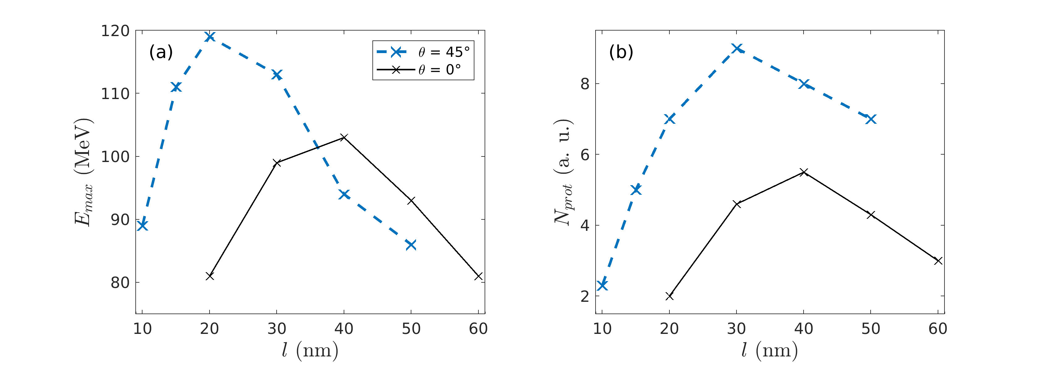
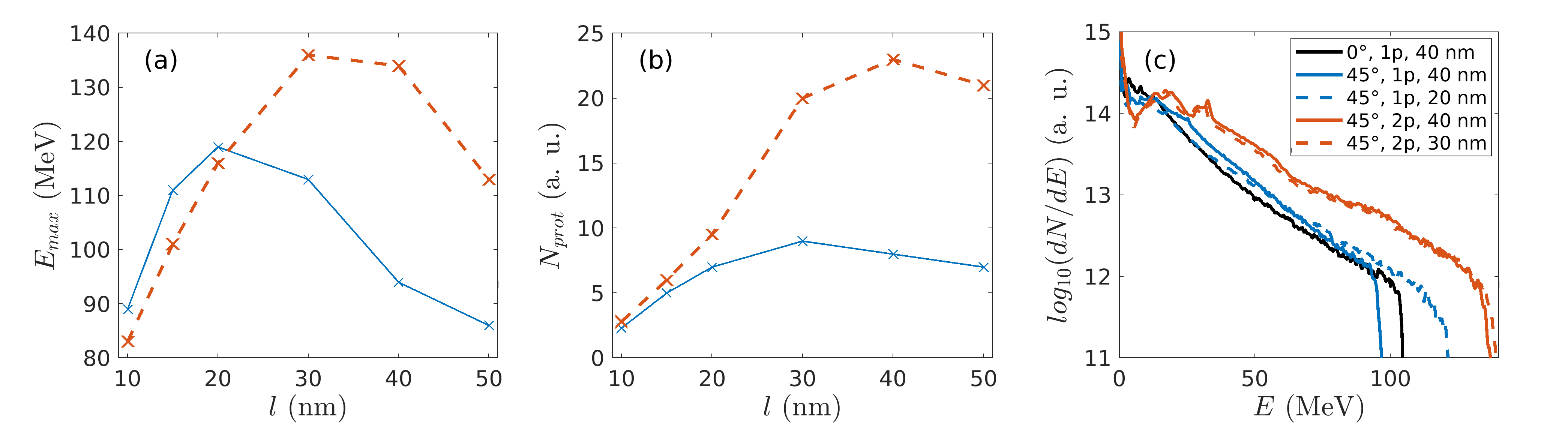
Figures 1(a,b) plot (as black solid curves) the target thickness dependence of the (a) maximum proton energy and (b) the number of high-energy (above 30 MeV) protons, as measured at the final simulation time (). Both quantities are found to be maximized at , close to , with proton energies as high as being then recorded. The number of high-energy protons is more sensitive to the target thickness than their maximum energy. Using or leads to a decrease in the proton number by a factor of 2 to 3 compared to the optimum case.
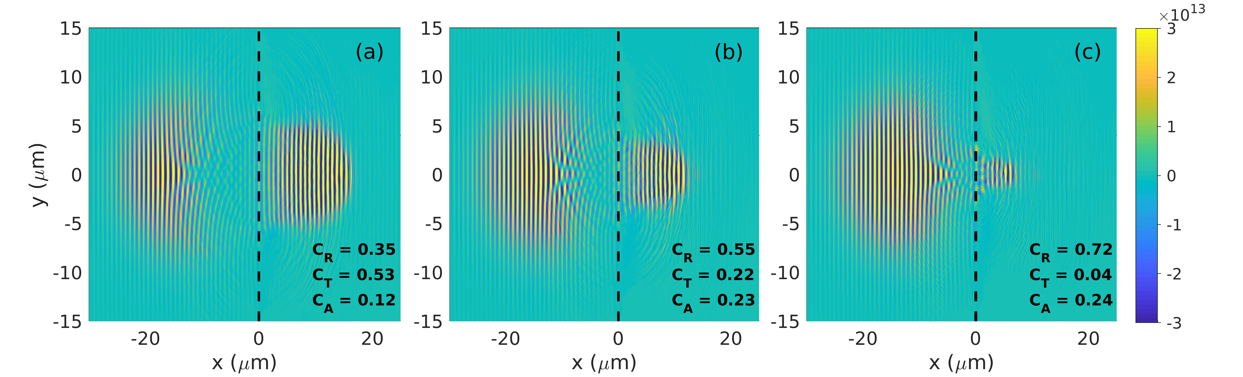
The optimum acceleration conditions are reached when RSIT occurs near the laser peak, which is confirmed by looking at the laser fields going through the target in Figs. 2(a-c), and by computing, for each thickness value, the transmitted (), reflected () and absorbed () fractions of the laser energy. While the laser pulse is significantly transmitted () and relatively weakly absorbed () through the foil [Fig. 2(a)], it gets significantly reflected () when the foil thickness is increased to [Fig. 2(b)], while its absorption is approximately doubled (). If the foil thickness is further increased to , the laser absorption remains similar, , but the transmission drops to a very low value, [Fig. 2(c)]. As a result of the RSIT then taking place late in the decreasing part of the pulse, the expanding protons no longer benefit from the boost in energy caused by volumetric electron heating at the laser peak (Mishra et al., 2018), and hence experience a weaker overall acceleration. This corresponds to the transition to the TNSA regime.
The absorption processes, and therefore the onset of RSIT, are expected to be altered when operating at oblique laser incidence. To assess the dependency of ion acceleration on the incidence angle, we now consider a laser pulse impinging at an angle onto the foil, all other physical parameters being kept constant. The simulation domain is also enlarged to . Figures 1(a,b) show (as blue dashed curves) that the optimum target thickness in terms of the maximum proton energy (resp. proton number above ) then drops from to (resp. ). This decrease seems reasonable since an oblique incidence angle leads to an increased interaction length (). More surprisingly, the decrease in the optimum target thickness goes along with a significant enhancement of the proton cutoff energy (by , up to ) and number (by ).
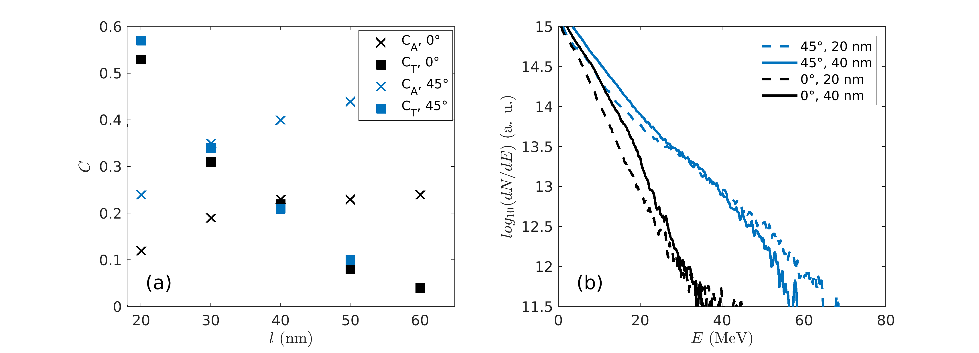
The improvement of the proton acceleration at oblique incidence can be explained by a more efficient mechanism for hot-electron generation. The absorption and transmission coefficients for the normal and oblique incidence are summarised in Fig. 3(a), showing an overall (approximately twofold) increase in the absorption coefficient at oblique incidence. For instance, the absorption coefficient at rises from at to at . By contrast, the transmission coefficient vs. thickness values are similar at and indicating that the transparency condition weakly depends on the incidence angle.
Figure 3(b) plots the electron energy spectra recorded after the on-target pulse maximum for two values of the the target thickness ( and ). They show that the higher laser absorption found at oblique incidence translates into an increase in both the number and temperature of the hot () electrons. The thicker (40 nm) target seems to mainly boost the number of hot electrons in both cases.
To understand the simulation results we adapt the thin-foil expansion model proposed in (Brantov et al., 2015) to the considered scenario. This model considers the expansion of a neutral plasma slab of initial thickness and uniform ion density . It assumes a Boltzmann electron distribution, , where is the electrostatic potential, is the (longitudinal) electron temperature and is the (time-decreasing) electron density at the target center (). The electrostatic field is taken to vary linearly inside the ion-filled region: for , where is the position of the ion front [] and is the field strength at the ion front. From this it readily follows that . Outside the ion cloud (), the electric potential obeys the nonlinear Poisson equation, . Multiplying this equation by and integrating it over yields . Furthermore, integrating Gauss’s equation over gives
| (1) |
where is the ion charge state. Introducing the error function, the above equation can be recast as
| (2) |
This formula assumes a 1D expansion geometry, and hence should overestimate the field strength when the ion front has moved a distance comparable with the transverse size of the sheath field (). A correction factor is thus applied to account for this effect:
| (3) |
where is the spatial dimensionality of the problem.
The electron temperature is assumed to follow the rise in the laser intensity , here taken in the form , and to stay constant in its decreasing part. The maximum electron temperature is inferred from the measured laser absorption: , where the factor corresponds to an averaging of the intensity over the laser focal spot. After the irradiation, the electrons start cooling down adiabatically. More specifically, evolves as
| (4) |
We have introduced the generalized adiabatic index for a relativistic 1D gas and the typical sound speed .
The knowledge of allows the velocity and position of the front ions to be advanced through
| (5) | ||||
| (6) |
It is to be noted that the model assumes a single ion species of charge state and mass ( is the proton mass). Although the expansion dynamics of light ions may be affected by that of heavier ions in a composite target (Brantov et al., 2006), we will take and in the following.
| (nm) | 20 | 30 | 40 | 50 |
| (MeV) | ||||
| (MeV) |
Equations (2)-(5) have been solved numerically for and . The results are gathered in Table 1. The values obtained at normal incidence are quite close to those observed in the simulations – although generally slightly overestimated – and reproduce the same trend, with an optimal target thickness between 30 and 40 nm. At oblique incidence, however, the model consistently overestimates the maximum proton energies, especially in the thicker targets (). It also predicts an optimal thickness of , larger than the one () observed in the simulations. This discrepancy between the simulations and the model suggests that the latter lacks a saturation mechanism that is mainly operative at oblique incidence and in thicker targets.
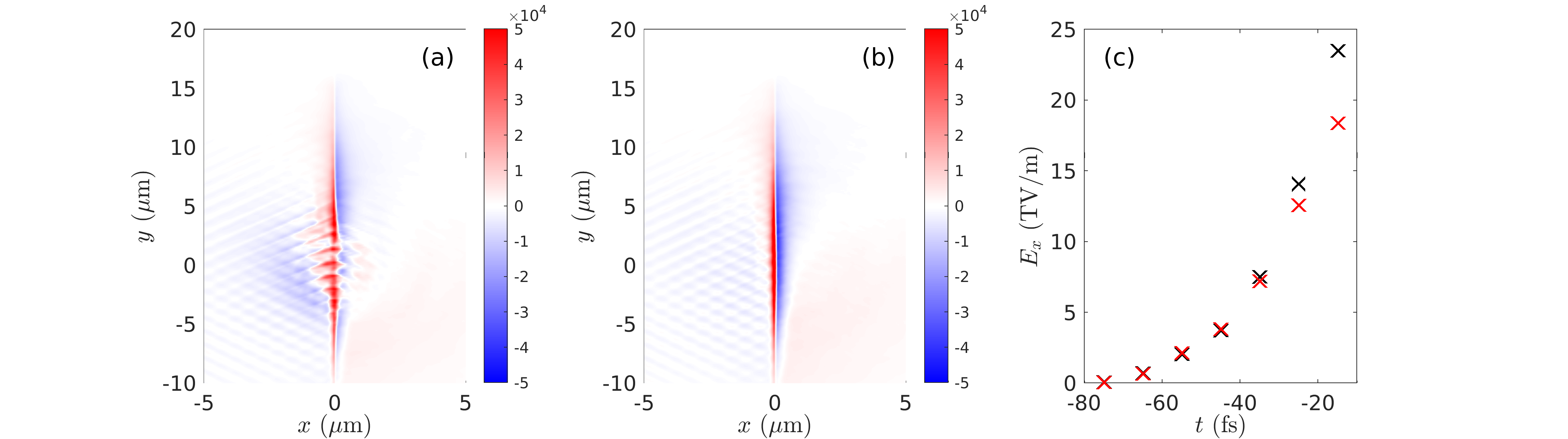
One such saturation-inducing effect is the generation of a strong magnetostatic field along the target surfaces [see Figs. 4(a,b), associated with and 40 nm], due to the electron current driven in the target in the transverse () direction. When volumetric electron acceleration is achieved (as is the case in the RSIT regime), this field is expected to increase with the target thickness [compare Figs. 4(a) and 4(b), where the field strength is seen to rise from at to at around the laser spot]. This field tends to deflect the hot electrons in the transverse direction, hence limiting the growth of the on-axis electrostatic sheath field () already before the on-target pulse maximum. This is evidenced in Fig. 4(c), which plots, for both and 40 nm, the temporal evolution of the maximum value of on axis at the rear surface. A similar magnetic effect has previously been shown experimentally to inhibit TNSA in micrometric targets (Nakatsutsumi et al., 2018). Therefore, although they are expected to produce stronger sheath fields, the thicker targets that turn transparent at do not yield faster ions, ultimately resulting in an optimum target thickness that is about half that found at .
3 Proton acceleration with colliding laser pulses in relativistically transparent foils.
We now turn to a configuration where the main laser pulse (of total energy of 16 J) is split into two half-pulses of equal energy (8 J) incident on the target at opposite angles (), similarly to the lower-intensity setup that was lately found to boost TNSA (Ferri et al., 2019). The other parameters remain the same as in the previous section.
Compared to that obtained with a single obliquely incident pulse, the optimal target thickness is increased when using two half-pulses, with best results obtained for , both regarding the maximum energy [Fig. 5(a)] and number [Fig. 5(b)] of accelerated protons. In addition, the proton maximum energy is increased from 119 MeV to 137 MeV. Remarkably, this enhancement goes along with a 3–4-fold rise in the number of high-energy () protons. When compared with the reference case at normal incidence, the two-pulse setup allows the maximum proton energy to be increased by , and the number of energetic protons to be multiplied by a factor of 4. Although the gain over the single obliquely incident pulse is less impressive, the predicted doubled optimal target thickness could ease the experimental investigation of ion acceleration from relativistically transparent solid foils, given the practical difficulties of manipulating such ultrathin targets. This applies, in particular, to modest-energy laser systems which may not allow achieving RSIT at handleable target thicknesses. Finally, figure 5(c) shows that the two-pulse scheme leads to substantial improvements in the proton energy spectra over the single-pulse case, both at normal and oblique incidence.
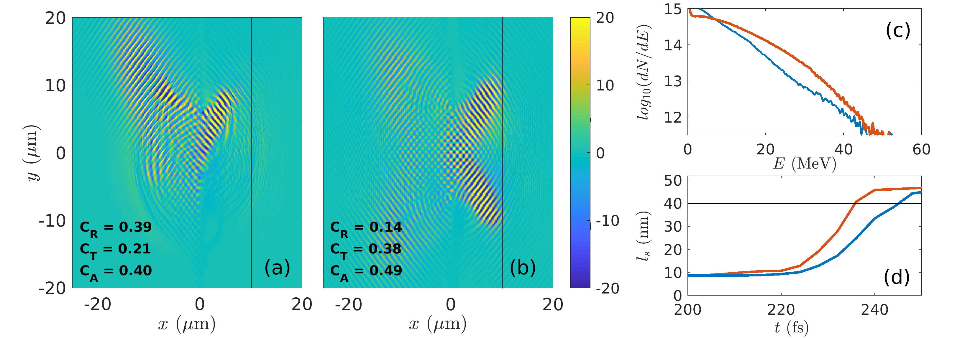
In the two-pulse scheme, the irradiated plasma area is comparable to that associated with a single pulse at oblique incidence. The larger optimum thickness and enhanced ion acceleration then mainly result from the modified electron dynamics in the two-pulse field distribution, as has been described earlier in the TNSA regime (Ferri et al., 2019). For a given target thickness, owing to the stronger electron heating, transparency is then more easily induced using two half-pulses. This is clearly shown in figure 6, with a transmission coefficient rising from to between the single- and two-pulse cases. By examining the laser field distributions in both configurations at various successive times, we checked that RSIT occurs earlier in time using two half-pulses, a result consistent with the increase in the absorption coefficient.
The stronger electron heating [cf Fig. 6(c)] that accounts for the enhanced laser absorption facilitates the induction of transparency. Figure 6(d) shows the temporal evolution of the relativistic skin depth during the interaction, with the plasma frequency and the electron Lorentz factor averaged over the target thickness and around the laser spot. As expected, the use of the two half-pulses yields a faster increase in with the laser intensity. We can consider that RSIT sets in when becomes higher than the initial target thickness (). In the two-pulse case, this criterion is fulfilled about prior to the laser peak time, which incidentally coincides with the onset of RSIT with a single pulse. We note that this delay between the onset times of RSIT using one or two pulses is consistent with the difference between the transmitted fractions of the laser field in figure 6.
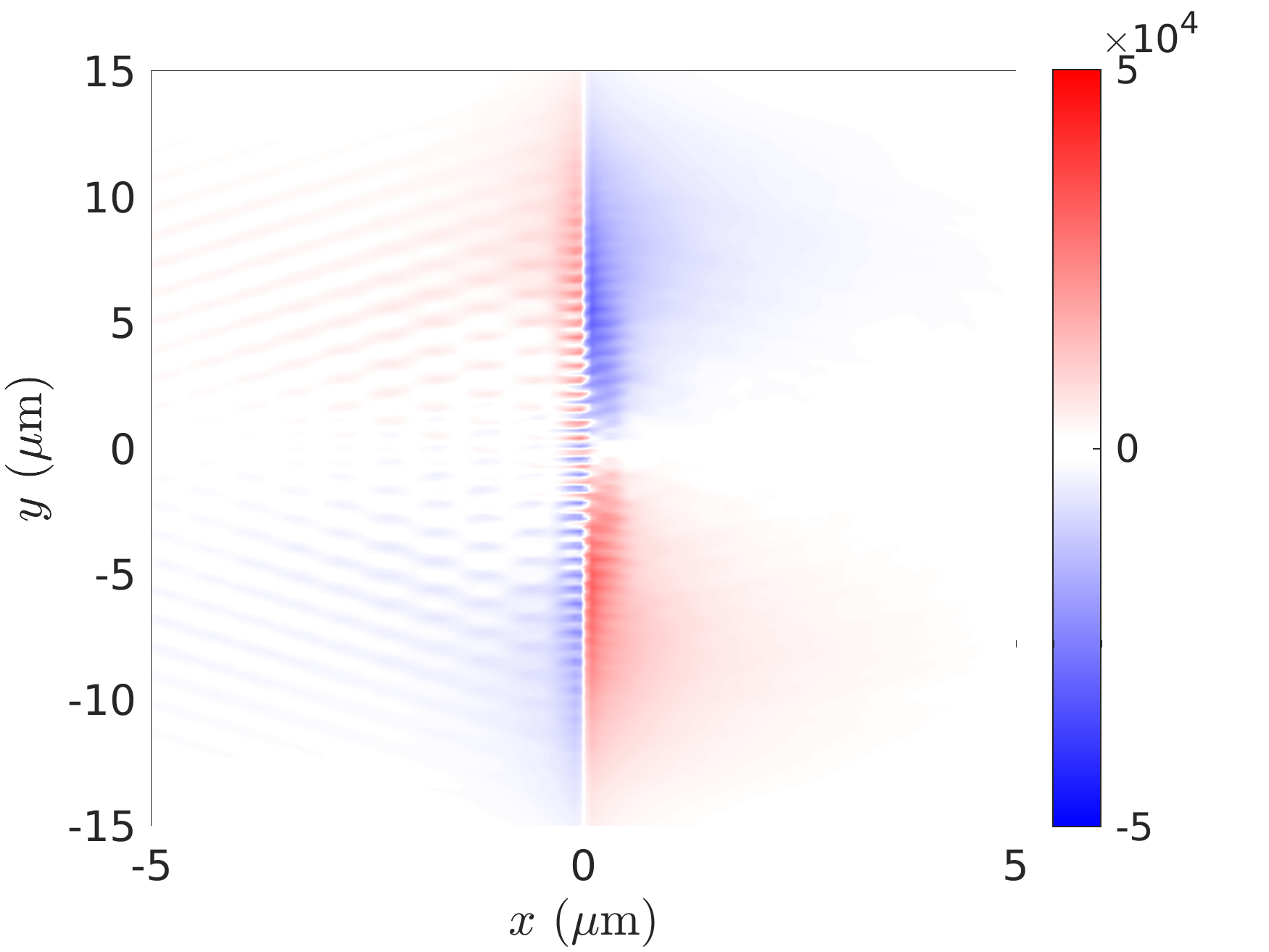
Furthermore, the symmetry (relative to the axis) of the two-pulse setup prevents the development of a strong surface magnetostatic field. Figure 7 shows this field 10 fs before the on-target laser peak for a 40 nm-thick target. As expected from the symmetry of the problem, the field vanishes on axis, and thus cannot counteract the sheath-field-enhancing effect of the stronger laser absorption.
4 Conclusions
Using 2D PIC simulations, we have examined the efficiency of laser-driven proton acceleration in relativistically transparent, ultrathin CH2 foil targets under different short-pulse irradiation conditions. As baseline laser parameters, we have considered a maximum intensity and a 38 fs pulse duration. First, we have showed that operating at oblique incidence can be beneficial to proton acceleration, owing to enhanced energy absorption into hot electrons. Yet, the optimum target thickness () is then reduced compared to that found at normal incidence (), as a result of strong () surface magnetostatic fields self-induced within the ion acceleration region. In a second step, we have studied a configuration in which the laser pulse is split into two half-pulses with the same total energy, incoming simultaneously on target but with opposite angles of incidence. This configuration enhances the electron heating while preventing the buildup of deleterious surface -fields within the laser spot. Not only does it allow one to use thicker targets than with a single obliquely incident pulse, but it also yields substantial increases in the proton numbers () and cutoff energies () over the baseline setup. Our study suggests that the constraints posed by nanometric targets in experiments on RSIT could be somewhat relaxed using a two-pulse scheme.
Acknowledgements
The authors would like to acknowledge fruitful discussions with I Thiele and L Yi. This work was supported by the Knut and Alice Wallenberg Foundation, the Swedish Research Council, Grant No. 2016-05012, and has received funding from the European Research Council (ERC) under the European Union’s Horizon 2020 research and innovation programme under grant agreement No 647121. The simulations were performed on resources at Chalmers Centre for Computational Science and Engineering (C3SE) provided by the Swedish National Infrastructure for Computing (SNIC).
References
- Arber et al. (2015) Arber, T. D., Bennett, K., Brady, C. S., Lawrence-Douglas, A., Ramsay, M. G., Sircombe, N. J., Gillies, P., Evans, R. G., Schmitz, H., Bell, A. R. & Ridgers, C. P. 2015 Contemporary particle-in-cell approach to laser-plasma modelling. Plasma Physics and Controlled Fusion 57 (11), 1–26.
- Brantov et al. (2015) Brantov, A. V., Govras, E. A., Bychenkov, V. Y. & Rozmus, W. 2015 Ion energy scaling under optimum conditions of laser plasma acceleration from solid density targets. Phys. Rev. ST Accel. Beams 18, 021301.
- Brantov et al. (2006) Brantov, A. V., Tikhonchuk, V. T., Klimo, O., Romanov, D. V., Ter-Avetisyan, S., Schnoerrer, M., Sokollik, T. & Nickles, P. V. 2006 Quasi-mono-energetic ion acceleration from a homogeneous composite target by an intense laser pulse. Phys. Plasmas 13 (12), 122705.
- Brenner et al. (2014) Brenner, C. M., Robinson, A. P. L., Markey, K., Scott, R. H. H., Gray, R. J., Rosinski, M., Deppert, O., Badziak, J., Batani, D., Davies, J. R., Hassan, S. M., Lancaster, K. L., Li, K., Musgrave, I. O., Norreys, P. A., Pasley, J., Roth, M., Schlenvoigt, H.-P., Spindloe, C., Tatarakis, M., Winstone, T., Wolowski, J., Wyatt, D., McKenna, P. & Neely, D. 2014 High energy conversion efficiency in laser-proton acceleration by controlling laser-energy deposition onto thin foil targets. Applied Physics Letters 104 (8), 081123.
- Bulanov et al. (2008) Bulanov, S. S., Brantov, A., Bychenkov, V. Y., Chvykov, V., Kalinchenko, G., Matsuoka, T., Rousseau, P., Reed, S., Yanovsky, V., Litzenberg, D. W., Krushelnick, K. & Maksimchuk, A. 2008 Accelerating monoenergetic protons from ultrathin foils by flat-top laser pulses in the directed-coulomb-explosion regime. Phys. Rev. E 78, 026412.
- Bulanov & Khoroshkov (2002) Bulanov, S. V. & Khoroshkov, V. S. 2002 Feasibility of using laser ion accelerators in proton therapy. Plasma Phys. Rep. 28, 453–456.
- Ceccotti et al. (2007) Ceccotti, T., Lévy, A., Popescu, H., Réau, F., D’Oliveira, P., Monot, P., Geindre, J. P., Lefebvre, E. & Martin, P. 2007 Proton acceleration with high-intensity ultrahigh-contrast laser pulses. Phys. Rev. Lett. 99, 185002.
- Clark et al. (2000) Clark, E. L., Krushelnick, K., Zepf, M., Beg, F. N., Tatarakis, M., Machacek, A., Santala, M. I. K., Watts, I., Norreys, P. A. & Dangor, A. E. 2000 Energetic heavy-ion and proton generation from ultraintense laser-plasma interactions with solids. Phys. Rev. Lett. 85, 1654–1657.
- Daido et al. (2012) Daido, H., Nishiuchi, M. & Pirozhkov, A. S. 2012 Review of laser-driven ion sources and their applications. Rep. Prog. Phys. 75 (5), 056401.
- d’Humières et al. (2013) d’Humières, E., Brantov, A., Yu. Bychenkov, V. & Tikhonchuk, V. T. 2013 Optimization of laser-target interaction for proton acceleration. Physics of Plasmas 20 (2), 023103.
- Esirkepov et al. (2004) Esirkepov, T., Borghesi, M., Bulanov, S. V., Mourou, G. & Tajima, T. 2004 Highly efficient relativistic-ion generation in the laser-piston regime. Phys. Rev. Lett. 92, 175003.
- Esirkepov et al. (2006) Esirkepov, T., Yamagiwa, M. & Tajima, T. 2006 Laser ion-acceleration scaling laws seen in multiparametric particle-in-cell simulations. Phys. Rev. Lett. 96, 105001.
- Ferri et al. (2018) Ferri, J., Senje, L., Dalui, M., Svensson, K., Aurand, B., Hansson, M., Persson, A., Lundh, O., Wahlström, C.-G., Gremillet, L., Siminos, E., DuBois, T. C., Yi, L., Martins, J. & Fülöp, T. 2018 Proton acceleration by a pair of successive ultraintense femtosecond laser pulses. Physics of Plasmas 25, 043115.
- Ferri et al. (2019) Ferri, J., Siminos, E. & Fülöp, T. 2019 Enhanced target normal sheath acceleration using colliding laser pulses. Communications Physics 2, 40.
- Geindre et al. (2006) Geindre, J. P., Audebert, P. & Marjoribanks, R. S. 2006 Relativistic gyromagnetic effects in ultraintense laser-matter interaction. Phys. Rev. Lett. 97, 085001.
- Haberberger et al. (2012) Haberberger, D., Tochitsky, S., Fiuza, F., Gong, C., Fonseca, R. A., Silva, L. O., Mori, W. B. & Joshi, C. 2012 Collisionless shocks in laser-produced plasma generate monoenergetic high-energy proton beams. Nature Phys. 8 (1), 95–99.
- Kar et al. (2012) Kar, S., Kakolee, K. F., Qiao, B., Macchi, A., Cerchez, M., Doria, D., Geissler, M., McKenna, P., Neely, D., Osterholz, J., Prasad, R., Quinn, K., Ramakrishna, B., Sarri, G., Willi, O., Yuan, X. Y., Zepf, M. & Borghesi, M. 2012 Ion acceleration in multispecies targets driven by intense laser radiation pressure. Phys. Rev. Lett. 109, 185006.
- Macchi et al. (2013) Macchi, A., Borghesi, M. & Passoni, M. 2013 Ion acceleration by superintense laser-plasma interaction. Rev. Mod. Phys. 85, 751.
- Maksimchuk et al. (2000) Maksimchuk, A., Gu, S., Flippo, K., Umstadter, D. & Bychenkov, V. Y. 2000 Forward ion acceleration in thin films driven by a high-intensity laser. Phys. Rev. Lett. 84, 4108.
- Markey et al. (2010) Markey, K., McKenna, P., Brenner, C. M., Carroll, D. C., Günther, M. M., Harres, K., Kar, S., Lancaster, K., Nürnberg, F., Quinn, M. N., Robinson, A. P. L., Roth, M., Zepf, M. & Neely, D. 2010 Spectral enhancement in the double pulse regime of laser proton acceleration. Phys. Rev. Lett. 105 (19), 195008.
- McKenna et al. (2003) McKenna, P., Ledingham, K. W. D., McCanny, T., Singhal, R. P., Spencer, I., Santala, M. I. K., Beg, F. N., Krushelnick, K., Tatarakis, M., Wei, M. S., Clark, E. L., Clarke, R. J., Lancaster, K. L., Norreys, P. A., Spohr, K., Chapman, R. & Zepf, M. 2003 Demonstration of fusion-evaporation and direct-interaction nuclear reactions using high-intensity laser-plasma-accelerated ion beams. Phys. Rev. Lett. 91, 075006.
- Mishra et al. (2018) Mishra, R., Fiuza, F. & Glenzer, S. 2018 Enhanced ion acceleration in transition from opaque to transparent plasmas. New J. Phys. 20 (4), 043047.
- Nakatsutsumi et al. (2018) Nakatsutsumi, M., Sentoku, Y., Korzhimanov, A., Chen, S., Buffechoux, S., Kon, A., Atherton, B., Audebert, P., Geissel, M., Hurd, L., Kimmel, M., Rambo, P., Schollmeier, M., Schwarz, J., Starodubtsev, M., Gremillet, L., Kodama, R. & Fuchs, J. 2018 Self-generated surface magnetic fields inhibit laser-driven sheath acceleration of high-energy protons. Nature communications 9 (1), 1–9.
- Patel et al. (2003) Patel, P. K., Mackinnon, A., Key, M. H., Cowan, T. E., Foord, M. E., Allen, M., Price, D. F., Ruhl, H., Springer, P. T. & Stephens, R. 2003 Isochoric heating of solid-density matter with an ultrafast proton beam. Phys. Rev. Lett. 91, 125004.
- Pelka et al. (2010) Pelka, A., Gregori, G., Gericke, D. O., Vorberger, J., Glenzer, S. H., Günther, M. M., Harres, K., Heathcote, R., Kritcher, A. L., Kugland, N. L., Li, B., Makita, M., Mithen, J., Neely, D., Niemann, C., Otten, A., Riley, D., Schaumann, G., Schollmeier, M., Tauschwitz, A. & Roth, M. 2010 Ultrafast melting of carbon induced by intense proton beams. Phys. Rev. Lett. 105, 265701.
- Romagnani et al. (2005) Romagnani, L., Fuchs, J., Borghesi, M., Antici, P., Audebert, P., Ceccherini, F., Cowan, T., Grismayer, T., Kar, S., Macchi, A., Mora, P., Pretzler, G., Schiavi, A., Toncian, T. & Willi, O. 2005 Dynamics of electric fields driving the laser acceleration of multi-mev protons. Phys. Rev. Lett. 95, 195001.
- Roth et al. (2001) Roth, M., Cowan, T. E., Key, M. H., Hatchett, S. P., Brown, C., Fountain, W., Johnson, J., Pennington, D. M., Snavely, R. A., Wilks, S. C., Yasuike, K., Ruhl, H., Pegoraro, F., Bulanov, S. V., Campbell, E. M., Perry, M. D. & Powell, H. 2001 Fast ignition by intense laser-accelerated proton beams. Phys. Rev. Lett. 86, 436–439.
- Scott et al. (2012) Scott, G., Green, J., Bagnoud, V., Brabetz, C., Brenner, C., Carroll, D., MacLellan, D., Robinson, A., Roth, M., Spindloe, C., Wagner, F., Zielbauer, B., McKenna, P. & Neely, D. 2012 Multi-pulse enhanced laser ion acceleration using plasma half cavity targets. Appl. Phys. Lett. 101 (2), 024101.
- Silva et al. (2004) Silva, L. O., Marti, M., Davies, J. R., Fonseca, R. A., Ren, C., Tsung, F. S. & Mori, W. B. 2004 Proton shock acceleration in laser-plasma interactions. Phys. Rev. Lett. 92, 015002.
- Snavely et al. (2000) Snavely, R. A., Key, M. H., Hatchett, S. P., Cowan, T. E., Roth, M., Phillips, T. W., Stoyer, M. A., Henry, E. A., Sangster, T. C., Singh, M. S., Wilks, S. C., MacKinnon, A., Offenberger, A., Pennington, D. M., Yasuike, K., Langdon, A. B., Lasinski, B. F., Johnson, J., Perry, M. D. & Campbell, E. M. 2000 Intense high-energy proton beams from petawatt-laser irradiation of solids. Phys. Rev. Lett. 85, 2945–2948.
- Tikhonchuk (2010) Tikhonchuk, V. 2010 Physics of laser-assisted ion acceleration. Nuclear Instruments and Methods in Physics Research Section A: Accelerators, Spectrometers, Detectors and Associated Equipment 620 (1), 1 – 13.
- Wilks et al. (2001) Wilks, S. C., Langdon, A. B., Cowan, T. E., Roth, M., Singh, M., Hatchett, S., Key, M. H., Pennington, D., MacKinnon, A. & Snavely, R. A. 2001 Energetic proton generation in ultra-intense laser-solid interactions. Phys. Plasmas 8 (2), 542.
- Yin et al. (2006) Yin, L., Albright, B. J., Hegelich, B. M. & Fernández, J. C. 2006 Gev laser ion acceleration from ultrathin targets: The laser break-out afterburner. Laser and Particle Beams 24 (2), 291–298.