A Sensorized Multicurved Robot Finger with Data-
driven Touch Sensing via Overlapping Light Signals
Abstract
Despite significant advances in touch and force transduction, tactile sensing is still far from ubiquitous in robotic manipulation. Existing methods for building touch sensors have proven difficult to integrate into robot fingers due to multiple challenges, including difficulty in covering multicurved surfaces, high wire count, or packaging constrains preventing their use in dexterous hands. In this paper, we present a multicurved robotic finger with accurate touch localization and normal force detection over complex, three-dimensional surfaces. The key to our approach is the novel use of overlapping signals from light emitters and receivers embedded in a transparent waveguide layer that covers the functional areas of the finger. By measuring light transport between every emitter and receiver, we show that we can obtain a very rich signal set that changes in response to deformation of the finger due to touch. We then show that purely data-driven deep learning methods are able to extract useful information from such data, such as contact location and applied normal force, without the need for analytical models. The final result is a fully integrated, sensorized robot finger, with a low wire count and using easily accessible manufacturing methods, designed for easy integration into dexterous manipulators.
I Introduction
Tactile sensing modalities designed for robot hands have made great strides over the past years. A number of comprehensive reviews [1, 2, 3, 4] describe numerous tactile sensors, based on various transduction methods (e.g., piezoresistance, piezocapacitance, piezoelectricity, optics, ultrasonics, etc.). Still, these advances in sensing modalities are only slowly translating to improved manipulation abilities for robot hands. In particular, we posit that a gap that has proven difficult to bridge has been that between stand-alone tactile sensors and fully integrated tactile fingers.
To illustrate this difference, consider a robot hand operating in cluttered, unstructured environments. Just like a stand-alone sensor, a tactile finger should be able to collect and report rich data characterizing touch. The information contained in the data will vary depending on the application, but typical use cases require the ability to infer touch location, characteristics of transmitted force, or perhaps the motor actions to be applied by the robot in response to the touch.
However, unlike stand-alone sensors, a tactile finger’s performance is also determined by the related problems of shape and coverage. When operating in clutter, a finger equipped with discontinuous “patches” of tactile sensing, and “unsensed” areas of higher curvature in between (such as edges or corners) has a high chance of making contact in a blind spot. Furthermore, integration into a dexterous manipulator (e.g., a multifingered hand with multiple tactile links on each finger) places tight constraints on wiring and packaging. Summarizing these goals, we are motivated to develop robotic fingers exhibiting high tactile acuity over complex, multicurved surfaces, with no “blind” edges or corners, in a self-contained package with few wires, and ready for integration into complete manipulators.
|
|
Traditionally, high accuracy contact localization has been achieved using dense arrays of individual taxels [5, 6, 7]. Each taxel’s response is processed individually (e.g., isolated, linearized, de-noised) in an attempt to prepare the data for upstream use, before it is offloaded from the sensor. Recent work on e-skin has obtained similar performance using soft materials resulting in flexible sensors [8, 9, 3, 10, 11, 12, 13, 14, 15, 16, 17]. However, reading high quality signals from individual taxels comes at a cost of increased manufacturing complexity, as taxels must be isolated from each other, high resolution arrays result in increased wiring, and deploying these sensors on non-planar and non-developable surfaces increases manufacturing complexity. In contrast to the use of carefully calibrated and isolated signals, recent years have seen increased adoption in robotics of machine learning methods that are well suited at quickly processing large amounts of “raw” data, with little to no pre-processing. We believe that this perspective can be used to relax some of these previously held assumptions (such as the “one taxel, one signal” approach), and enable new approaches to tactile sensing.
We base our work on the key concept of overlapping optical signals. To illustrate this concept, consider one light emitter (in our case, an LED) and one light receiver (a photodiode) embedded in a transparent medium acting as a waveguide. Any deformation of this medium (e.g., due to contact with an external indenter) will change the amount of light traveling from the LED to the diode, providing a measurable signal that is related to contact with the indenter.
Taking this concept further, consider multiple light emitters and receivers embedded in the same medium. Any external touch which deforms the medium will lead to changes in signal between multiple LED/diode pairs. In fact, assuming an equal distribution of LEDs and diodes, the total number of signals we can measure is , or the amount of light transmitted between each LED and each photodiode. Because each LED/diode pair has its own spatial receptive field within the active sensing area, and these receptive fields overlap, we call this general method spatially overlapping signals. The total number of signals we can collect is quadratic in the number of individual sensing units (LEDs and diodes), giving us extremely rich data with relatively few wires.
We note that the use of spatially overlapping signals is not necessarily restricted to using optics as an underlying transduction method. Other methods can be used, such as piezoresistance or electrical impedance. We chose light transport in our work due to attractive properties such as simple and low-cost manufacturing (the medium consists simply of a transparent polymer, as opposed to piezoresistive materials), low hysteresis, and fast switching and sampling.
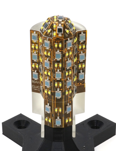
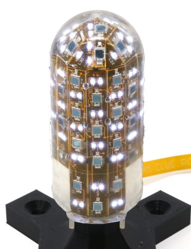
The finger we demonstrate in this work (Fig. 1) comprises a hemispherical tip attached to a cylindrical body. The sensorized areas of the finger include the complete hemispherical tip, and half the circumference (180∘) of the cylindrical body. The finger contains 32 LEDs and 30 photodiodes, giving us a total of 960 signals. As the finger makes contact with an external surface, many of these signals change, with the sign and magnitude of the change for each signal depending on the deformation of the transparent medium, as well as the relative position of the respective LED and diode.
How can we make use of this rich dataset? Building an analytical model of how each signal is affected by contact characteristics is a daunting task; furthermore, any such model would depend on knowing the exact locations of the terminals in the sensor, thus requiring very precise manufacturing. In contrast, we propose a purely data-driven approach, where the mapping from our signals to the quantities of interest is learned directly from data. This approach is enabled by recent advances in machine learning allowing us to train regressors and classifiers on high-dimensional feature spaces, as is the case for our tactile finger.
A data-driven approach needs ground truth for training. We thus collect labeled ground truth data by indenting our fingers in controlled conditions, using an indenter mounted on a robot arm and equipped with a load cell. For any indentation, we record the exact location of contact (based on the robot arm encoders) and the normal force (reported by the load cell). For multitouch, we use a manual procedure to record the identity of discretized finger cells being touched. We use this dataset to train models for predicting contact location(s) and normal force based on the optical signals recorded by the finger. We use deep neural networks for both regression (for location and force) and classification (multitouch detection).
We summarize the contributions of the this paper as follows: To the best of our knowledge, we introduce the first multicurved robotic finger that can localize touch with sub-millimeter accuracy and also accurately determine normal contact force over non-developable three-dimensional surfaces (such as a cylindrical body with a hemispherical tip), in a fully integrated, finger-shaped package. To achieve this, we show that purely data-driven methods can extract useful information from overlapping optical signals, enabling fast operation, easily accessible manufacturing methods, and a low wire count for the integrated finger.
II Related Work
Optics-based tactile sensing has a long history of integration in robotic fingers and hands [18, 19, 20]. Of particular interest is the use of CCD or CMOS sensors recording light patterns through a robotic tip. This includes the GelSight [21], TacTip [22] and GelSlim [23] sensors, which can retrieve minute details of surface texture, and also achieve super-resolution and hyperacuity. However, the imaging array must image the entire touch area, leading to bulky assemblies or partially sensorized fingers. In our work, the sensing terminals are fully distributed, allowing for coverage of large areas and curved geometry. Waveguides are also used as force transducers [24, 25] with very high sensitivity, but without contact localization.
Previous work also overlapped multiple optical signals in the same waveguide [26] in order to enable a reconstruction of the applied pressure map, but no quantitative results on reconstruction or localization accuracy were presented. Other studies used a one-to-many [27] or one-to-one [28] paradigm for signals between light emitters and receivers, as opposed to the many-to-many paradigm we use here in order to increase localization accuracy. Reflection and refraction were also used to build an IR touch sensor that doubles as a proximity [29] or proprioceptive sensor [30], but without localizing contact.
Extracting contact information from overlapping signals has been done in the context of methods inspired by Electric Impedance Tomography (EIT) [31, 32, 33, 34]; for a comprehensive survey on the use of EIT for robotic skin see the work of Silvera et al. [35]. EIT offers stretchable, continuous tactile sensing with the ability to discriminate multiple points of contact. An intrinsic advantage of EIT is that it can produce full contact maps for multi-touch situations, an ability which we have not yet investigated with our method. However, EIT methods require an analytical model for the internal conductivity to construct an image showing the areas where strain is applied. In contrast, our approach is completely data-driven and does not require knowledge of a forward model of the sensor, which allows us to embed terminals along complex multicurved boundaries of three-dimensional sensing areas.
Other sensors also use a small number of underlying transducers to recover richer information about the contact, using super-resolution or related methods [36, 22, 37, 38]. In comparison, our data-driven approach allows arbitrary placement of transducers inside the finger, and thus coverage of complex multicurved surfaces. Random location of transducing terminals in a soft finger has been used for texture discrimination [39], but without the ability to localize contact or measure force. The BioTac sensor [40] pioneered an overlapping-signals approach for tactile sensing by measuring impedance changes in a fluid, in addition to other multimodal data (fluid temperature and pressure changes due to contact). However, impedance signals were measured between a single ground electrode and multiple working electrodes, producing a number of signals that was linear in the number of electrodes, as opposed to our approach of measuring an optical signal between any emitter and any receiver, and thus obtaining a number of signals quadratic in the number of terminals.
In the absence of learning-based or super-resolution techniques, high spatial acuity has been achieved through high-resolution taxel arrays [5, 6, 7], which cannot cover curved surfaces. The highly active field of e-skin research [8, 9, 3, 10, 11, 12, 13, 14, 15, 16, 17] shows promise to overcome such problems through flexible sensors that include features like high density of sensing elements, multimodal sensing, and even actuation [41]. Flexible tactile skin has also been used to sensorize gloves for collecting tactile data on human manipulation [10], and taxelized skins can inherently distinguish multitouch conditions. However, manufacturing complexity, along with system-level issues such as wiring, addressing, signal processing of multiple sensor elements or off-board amplification electronics remain important roadblocks on the way to using e-skin for fully integrated sensorized robot fingers exhibiting sub-millimeter localization accuracy as well as complete coverage of complex non-developable geometry, as the one we present here.
Machine learning methods are seeing increased used for manipulation based on tactile data. Examples include grasp adaptation or object identification through tactile sensing [42, 17, 43, 44], slip and rotation detection [45], learning to discriminate between different types of geometric features [46] using the BioTac sensor [40], learning the mapping between tactile signal variability and grasp stability [47] with the MEMS-based Takktile sensors [48], using recurrent neural networks for proprioception on soft manipulators [49], and classifying different touch gestures on a novel EIT-based skin [50]. Here, we apply data-driven methods to learn a model of the sensor itself and believe that developing the sensor simultaneously with the learning techniques that make use of the data can bring us closer to achieving complete tactile systems.
III Tactile Finger Design and Manufacturing
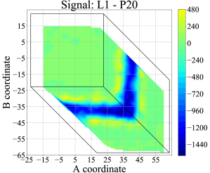
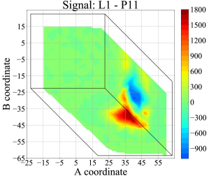
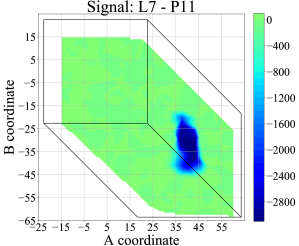
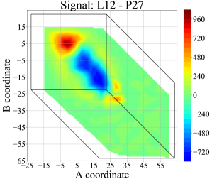
Our tactile robotic finger is constructed using LEDs and photodiodes embedded in a clear elastomer which acts as a waveguide. Each possible combination of an LED with a photodiode is considered a sensing pair. Our method relies on the fact that, when the elastomer is deformed under contact, the surface normal is perturbed and light is deflected, producing a measurable change in the output of one or more photodiode(s). Each LED/photodiode pair has a signal associated to it, represented by the amount of light received by the respective photodiode from the respective LED, and a receptive field, represented by the area on the elastomer that can be disturbed to produce change on this signal. Because we have many LEDs and photodiodes, and light can travel a considerable distance inside the elastomer, the receptive fields of different pairs overlap significantly. A single contact can stimulate many different sensing pairs which is why we refer to this methodology as spatially overlapping signals. Note that this method gets rid of the traditional notion of a taxel, as we produce signals with a combination of an emitter and receiver without enforcing a particular location for either one.
III-A Finger geometry and surface parameterization
We start with a 3D printed skeleton (Formlabs Form2, clear resin) designed to be the distal link in a robot hand. This skeleton provides a base on which we will mount our individual sensing terminals (LEDs and photodiodes). The geometry of our finger is informed by the requirements of the task as well as intuition. We chose the outer geometry (including the transparent layer) to be appropriate for a finger operating in clutter, maximizing the sensorized area while avoiding sharp edges and corners, which are not conducive to creating stable contacts. The outer shape thus consists of a 36 mm diameter hemisphere, mounted on a cylindrical base of the same diameter and 72 mm height.
Our goal for the functional area of the finger (the area where touch can be sensed) was to avoid any blind spots in areas likely to make contact. We thus selected as an active area the complete tip hemisphere, as well as 180∘ around the circumference of the cylindrical body. The only “unsensed” area of the finger is the back (half the circumference) of the cylindrical part. The transparent waveguide layer extends throughout the sensorized area of the finger. Based on previous experiments on planar prototypes [51], we selected 7 mm as the thickness of the transparent layer.
|
|
The rigid skeleton acts as a foundation for the transparent layer, as well as a support for the LEDs and photodiodes. The electronic components are mounted on the flexible circuit board (flexboard) shown in Fig. 2. Since most components require locally flat mounting areas, the flexboard alternates flat strips (enforced with stiffeners) with flexible “creases”. The rigid skeleton is designed with flat facets to accommodate this flexboard geometry. These flat faces follow the smooth curvature of the finger surface above, and thus the electronic components radiate and receive most light in the same direction as the surface normal. The left-most and right-most faces are the exception to this rule, as they are oriented such that LEDs will radiate light parallel to the surface instead of normal to it. Light emitted in this way can travel all the way to the other side of the finger as it bounces through the reflective coating, increasing spatial coverage for a subset of signals.
Since the surface of our finger is a (multicurved) two-dimensional manifold (embedded in three dimensions), we parameterize it using two dimensionless variables . We use the surface parameterization introduced by Roşca[52] for spheres, which we extend to cover the cylindrical component of our finger (see Appendix). The resulting parameterization, illustrated in Fig. 2, avoids singularities and aims to preserve distances uniformly across the sensorized surface of our finger.
III-B Manufacturing
We use a cyanoacrylate adhesive to bond the flexboard to the skeleton and then connect a 380 mm flat flexible cable (FFC) to the backside of the finger. Once the flexboard is glued, we treat all the surfaces with a silicone primer (MG Chemicals SS4120) to promote bonding of the transparent waveguide layer to the skeleton and sensor board.
We then cast the transparent layer, for which we use Polydimethylsiloxane (PDMS). The stiffness of the elastomer can be adjusted by changing the ratio of curing agent to PDMS. We prepare the main layer of elastomer with a ratio of 1:30, which we empirically observed to produce a stiffness of approximately 2.8 N/mm. We consider it desirable for this first layer to be soft because our signals are proportional to surface deformation; thus, the softer the material, the less force is required to achieve a deformation that our electronics can detect. After mixing the PDMS with the curing agent, we degas and pour the solution into the mold. We cure the PDMS at 80 C for 6 hours. After this process, we remove the finger from the mold to obtain a fully clear finger as shown in Fig. 1.
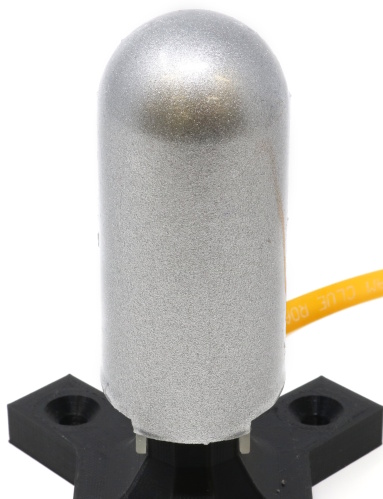
To complete the finger, we add a thin outer layer with a dual purpose: this layer reflects light back into the transparent elastomer that otherwise might refract out, and blocks ambient light. Following the example of the GelSight sensor [21], we use Bronzing Powder #242 from Douglas and Sturgess. After demolding the finger we use a makeup brush to apply the reflective powder onto the PDMS surface, then add an additional thin PDMS layer. This additional layer has a 1:10 ratio of curing agent, as well as 1% by weight reflective powder mixed in. We add this layer via dipping the finger in a vat, followed by curing at 80 C for 40 minutes. The process of adding the reflective powder onto the PDMS, followed by an extra PDMS layer to protect it is repeated two more times.
III-C Sensor board and electronics
The flexboard contains 57 individual LEDs (Bivar SM0805UWC), 30 photodiodes (Osram BPW 34 S E9601), 15 operational amplifiers (AD8616), two 32 channel multiplexers (ADG732) and one FFC connector with 14 positions (Hirose FH34SRJ-14S). Many of the Bivar LEDs are grouped in pairs, comprising 2 units placed 2 mm apart and wired together. Such a pair is the logical and functional equivalent of a single LED with a larger surface area. We refer to such pairs as simply “one LED” for the rest of the paper. Using this convention, our board comprises a total of 32 “logical” LEDs. Since we only turn on a single LED pair at a time (see below), and with each LED drawing 20 mA, our board uses a total of 200 mW power during operation.
Similarly, we selected our photodiode for its large active sensing area of 7 mm2. We aimed for large surface areas in both our light emitters and receivers in order to obtain a smooth response as light paths are altered by the presence of an indenter (as opposed to a binary-like signal that occurs when a small area emitter or receiver is blocked or revealed). Each photodiode signal is amplified using a transimpedance amplifier with a feedback resistor of 249 kOhms.
In order to measure the light transmitted between each LED and each diode individually, we use one multiplexer to select which LED to drive and the other multiplexer to select which photodiode to read. We turn on one LED at a time, and read the signals from each photodiode in sequence. We also take an additional reading of each photodiode with all LEDs turned off, in order to account for any traces of ambient light that might have penetrated our outer layer. We record all the ensuing 960 signals at a rate of 60 Hz.
|
|
||||
|
Since we measure light transport between each LED and each photodiode, we want to ensure that the light emission from each LED is bright enough to reach distant diodes, but also that it does not saturate nearby diodes. We use an AD8616 operational amplifier on the output of the Teensy digital to analog converter to control the brightness for each individual LED. For every LED/diode pair, we choose a dedicated LED brightness level such that the response of the diode in the undisturbed state of the finger is close to the middle point of the diode’s output range. This ensures that, in the presence of deformation, each of our signals has “headroom” to either increase or decrease, depending the position of the LED and diode relative to the indenter.
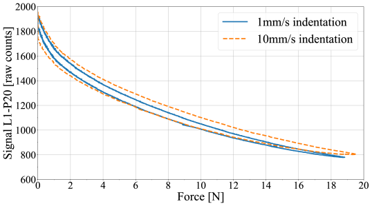
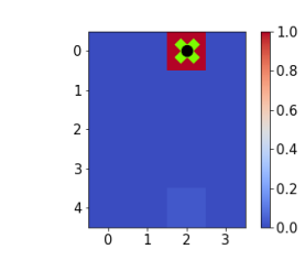
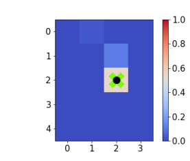
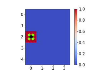
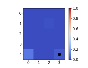
Fig. 3 illustrates the concept of a receptive field for a number of representative LED/diode pairs using data collected from the finger. Fig. 4 also shows a representative hysteresis plot, collected for raw signal L1-P20 on two indentation-release cycles performed at different velocities in the middle of the receptive area for that signal.
IV Learning from Tactile Signals
Our signals are directly correlated with the surface deformation of the finger. However, building an analytical model to reconstruct the state of the surface based on the collected signals would be a daunting task. Thus, this methodology is better fitted to using purely data-driven algorithms to learn the mapping between this rich set of signals to various touch parameters of interest. In this study we focus on determining the location of a contact and the applied normal force.
IV-A Data collection
IV-A1 Single touch data
For cases where the finger is contacted in a single location, we automated data collection with a Universal Robot UR5. We use a custom end effector mounting for a linear actuator (Physik Instrumente M-235.5DD) which is fitted with a load cell at its end to record force measurements (Futek LSB205 10 lbs). At the other end of the load cell we can mount multiple tips with different geometries.
With this setup, we probe the finger at random locations with different tips mounted on our load cell. These random locations are sampled from the defined region that represents our sensorized finger surface. It must be noted that all indentations for this study are normal to the finger surface. We define a dataset to contain 100 random locations spread throughout the region in space, with the caveat that we enforce a minimum distance of 4 mm between locations to explore the full surface more homogeneously. (Any new randomly selected location is rejected if it is closer than 4 mm to another sample in the same dataset.)
For every location in the region we follow the same procedure. We use the parameterization described above to go from the location to its corresponding Cartesian coordinates, and compute inverse kinematics for the robot to reach that point in space. The robot positions the indenting tip normal to the surface at a distance of 20 mm. At this point we advance the probe until we find the finger surface using the force measurements from the load cell. Having established the finger surface, we start logging data from a depth of -1 mm (negative depths should be interpreted as the tip being above the surface) and up to 4 mm. (Indentations with the planar tip only go to a depth of 3 mm to avoid exceeding the load cell maximum force rating of 10 lbs). We collect data at 0.1 mm depth intervals, which yields a total 51 measurements at different depths for every location, hence a dataset with 100 locations constitutes 5100 data points.
Each measurement results in a tuple of the form where is the indentation location in space, is the depth at which the measurement was taken, is the measured force in newtons, is the id corresponding to the indenter geometry used and is the feature vector with dimension 990 containing all light measurements between all 32 LEDs and 30 photodiodes and an additional 30 measurements which correspond to turning off all LEDs and measuring any traces of ambient light received by each photodiode, which is then subtracted from the main 960 signals.
Using this dataset, we checked how many of these raw signals carry useful information. We consider a signal as useful if, in response to an indentation anywhere on the finger surface, the signal changes by more than three times its own standard deviation in the undisturbed state (used as a measure of noise). We found that 917 our of 960 signals exceed this threshold, confirming the hypothesis that our overlapping signals approach leads to a large number of useful signals.
IV-A2 Multi-touch data
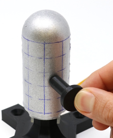
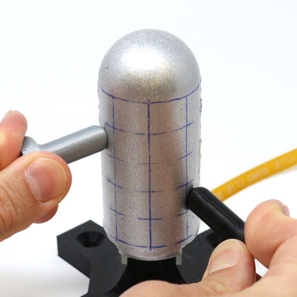
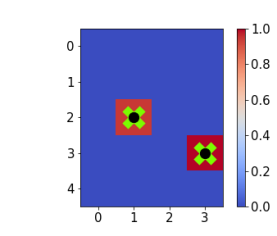
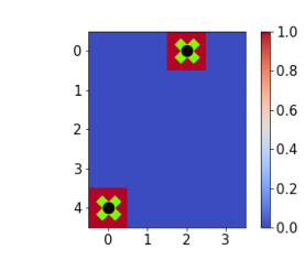
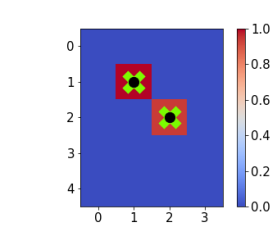
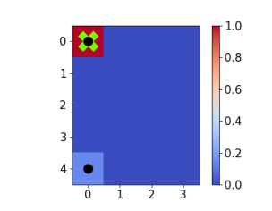
To collect data where the finger is potentially touched in multiple locations, we revert to a manual procedure. We divide the cylindrical part of the finger into a 45 regular grid. For one data point, a human experimenter contacts the finger in either a single cell, or simultaneously in two cells, chosen at random. Contact is made in all cases with hemispherical indenters (10 mm diameter). Each measurement thus results in a tuple of the form , where is a binary signal indicating if cell is being contacted, and the feature vector comprises tactile finger signals as above. We note that contact forces are not measured in this case.
IV-B Learning algorithms
For all experiments on our finger, we use feed forward neural network architectures. The architectures are slightly customized to support the related task. First, we describe the architecture for contact localization and force detection, followed by the neural network for multi-touch detection.
For localization and force prediction, we use a multi-task neural network with five hidden layers. Each hidden layer uses batch normalization and the ReLU activation function. The first three hidden layers are shared between both tasks, with 512, 256 and 128 activation units respectively. Afterwards, each output has two individual hidden layers with 64 and 32 hidden units respectively. We use mean squared error as a loss function. The network is trained for 600 epochs with ADAMoptimizer, a batch size of 128 and an initial learning rate of 0.001. After 500 epochs the learning rate is decreased to 0.0001. For localization prediction, the training dataset is filtered to only use positive depth, because the network cannot be expected to predict location when touch is not occurring.
Collecting precise multi touch data would require two robotic arms operating on the same finger without colliding with each other, simultaneously. In the absence of such a setup, we used a simpler manual procedure. We divided a section of the finger into a 45 grid cell (in total 20 cells) and collected data via manual indentation. The training process randomly selects one or two out of the 20 cells and shows their identity to the experimenter. The experimenter then indents the respective cells, and records the ensuing tactile data. We note that exact contact force is unavailable when using this procedure.
The resulting dataset is one order of magnitude smaller than the ones obtained with our automated process and, therefore, a simpler neural network is required. For multi-touch prediction, a two hidden layer feed forward neural architecture is used with 128 and 32 hidden units respectively. The hidden layers use the ReLU as activation function, but no batch normalization. The output consists of 20 independent binary predictions, each indicating the probability of touch for a certain cell. For this task, we used the sigmoid cross entropy loss. The network was trained for 400 epochs with ADAMoptimizer with a batch size of 128 and initial learning rate of 0.001, which was reduced to 0.0001 after 200 epochs.
V Results
V-A Touch localization and force detection
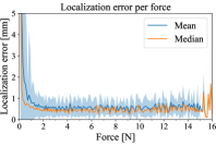
We first quantify the ability of our finger to predict the location of touch. We perform this test on a corpus of single-touch data comprising 4,896 indentations at 96 different locations and with different forces, collected using the procedure outlined in IV-A1. Fig. 5 shows the localization error at different force levels over the entire test set (mean and median). Note that while our prediction is made in the dimensionless space, we first convert both the prediction and the ground truth location back to Cartesian space in order to calculate the error in distance units (mm). We also note that the smallest force that our load cell can accurately detect is 0.2 N, and any force measurement below that value indicates either no contact, or very slight touch.
We observe that our finger quickly achieves sub-millimeter accuracy in touch localization, once the contact force exceeds 0.2 N. The error continues to decrease until a force level of approximately 1 N, at which point performance stabilizes throughout the rest of the range of forces we tested. At 0 contact force (no touch), the localization error is 30.3 mm (median), in line with a random chance guess.
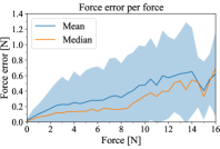
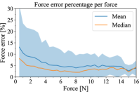
We now turn our attention to the ability to also predict normal contact force. Using the same datasets as before, we train a neural network regressor to predict contact normal force, using load cell data as ground truth. The absolute error (difference between predicted and real force), as well as the error as a percentage of the ground truth applied force, are both shown in Fig. 5, for different contact forces.
We note that the relative error is below 10% (median) even for very light touches, and reduces to as low as 2% (median) in the middle of our range (around 8 N). At that point, relative error stabilizes around 3% (median) and 5% (mean) for the rest of the range, up to 16 N. In absolute terms, this means that while error grows together with the applied force, it does so slowly, and, for a force range between 2 and 9 N, the median error is approximately constant, and below 0.2 N.
 |
 |
 |
 |
 |
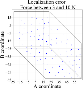 |
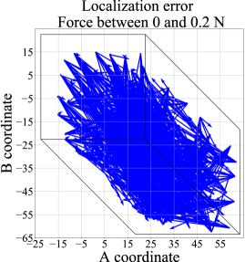
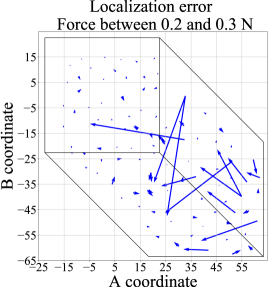
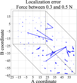
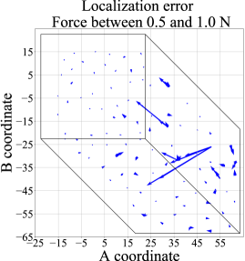
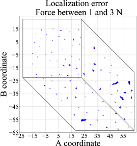
For more insights into how localization performance varies across its surface, we would like to study if the magnitude or direction of the error is affected by the area of the finger that is being touched. Fig. 6 shows this error for every data point, grouped by force levels. For clarity, the data is shown in the two-dimensional space, as illustrated in Fig. 2 and formally defined in the Appendix. We notice that at no contact and below a force level we can reliably detect (0 to 0.2 N), errors are in line with random guesses. At low forces (0.2 to 0.5 N) most of the functional area of the finger has good accuracy, with the errors occurring along the edges of the cylindrical part. For forces beyond 1 N, larger errors have been eliminated throughout the functional area.
V-B Robustness to indenter shape
The results shown so far have been obtained by using a single indenter tip. What happens if the shape of the indenter varies? Furthermore, what is the performance level if, at test time, the finger makes contact with an indenter different from the one(s) using during training? These analyses would be indicative of performance in complex environments, where the robot might interact with objects of varying, and potentially unknown shape, and in various configurations.
To evaluate this performance, we collected data using multiple indenters. In addition to the 10 mm diameter hemispherical tip used so far, we added a planar tip (circular with a 15 mm radius), a sharp corner, and an edge used in two different orientations (horizontal and vertical), for a total of five different indentation geometries. We used this dataset to test localization performance with two different approaches.
 |
 |
 |
 |
 |
 |
 |
 |
 |
 |
| Tip | Model | Error (mm) | Error (mm) | Error (mm) | Error (mm) | Error (mm) | |||||
|---|---|---|---|---|---|---|---|---|---|---|---|
| for forces | for forces | for forces | for forces | for forces | |||||||
| 0.2-0.3 N | 0.3-0.5 N | 0.5-1.0 N | 1.0-3.0 N | 3.0-10 N | |||||||
| Mean | Median | Mean | Median | Mean | Median | Mean | Median | Mean | Median | ||
| Edge (H) | Leave-one-out | 13.0 | 7.5 | 8.3 | 4.0 | 4.2 | 2.5 | 2.5 | 1.7 | 3.7 | 2.1 |
| All inclusive | 7.8 | 2.9 | 3.2 | 1.9 | 1.6 | 1.2 | 1.0 | 0.9 | 0.8 | 0.7 | |
| Edge (V) | Leave-one-out | 12.6 | 13.0 | 6.8 | 6.3 | 3.8 | 3.3 | 3.0 | 2.9 | 1.8 | 1.7 |
| All inclusive | 2.8 | 3.6 | 2.7 | 3.2 | 1.6 | 1.6 | 1.1 | 1.1 | 0.8 | 0.9 | |
| Planar | Leave-one-out | 7.5 | 3.3 | 5.6 | 2.7 | 2.8 | 2.0 | 1.9 | 1.5 | 1.5 | 1.3 |
| All inclusive | 1.2 | 0.9 | 0.9 | 0.8 | 0.7 | 0.6 | 0.6 | 0.5 | 0.6 | 0.5 | |
| Spherical | Leave-one-out | 4.5 | 2.0 | 3.1 | 1.8 | 2.4 | 1.3 | 2.1 | 1.2 | 2.5 | 1.4 |
| All inclusive | 1.2 | 0.9 | 0.9 | 0.8 | 0.7 | 0.6 | 0.6 | 0.5 | 0.6 | 0.5 | |
| Corner | Leave-one-out | 2.7 | 1.6 | 1.7 | 1.3 | 1.4 | 1.1 | 1.2 | 1.0 | 1.4 | 1.1 |
| All inclusive | 1.2 | 0.9 | 0.9 | 0.8 | 0.7 | 0.6 | 0.6 | 0.5 | 0.6 | 0.5 | |
| Average | Leave-one-out | 8.1 | 5.5 | 5.1 | 3.2 | 2.9 | 2.0 | 2.1 | 1.7 | 2.2 | 1.5 |
| All inclusive | 2.9 | 1.8 | 1.7 | 1.5 | 1.1 | 0.9 | 0.8 | 0.7 | 0.7 | 0.6 | |
First, in order to test performance for an indenter shape not seen during training, we used a leave-one-out procedure: for any indenter tip, we trained a regressor (similar to the one used before) on data from all the other tips in our set, but excluding the tip being tested. We then checked localization performance on the tip that had been excluded from training. The second approach aimed to test performance over multiple indenter shapes, but assuming data from each indenter is available for training. We thus trained one model on data from all five indenters, and tested this all-inclusive model on separate test data from each tip. All results are shown in Table I.
We notice that high localization accuracy generalizes to multiple indenter geometries. If data for all indenters is available for training, even light touch can be localized with 3 mm median accuracy for 4 out of 5 indenters, further reducing to sub-mm as contact forces increase. Even when the finger is contacted by a never-seen-before indenter, it can localize touch well, as long as the model has seen indenter shape variations in training. Performance increases with normal contact force, with 2 mm or lower median localization error typical for never-seen-before indenters once force exceeds 0.5 N.
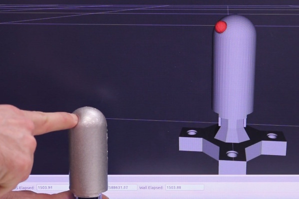
To illustrate the performance of contact localization and force detection, as well as robustness for an indenter geometry not seen in training, the accompanying video shows in real-time the predictions made as our robotic finger is indented by an experimenter using their own finger.
V-C Detection of multiple touch points
Finally, all of our results so far assume a single touch point on the finger. Such an assumption is applicable in some real-life cases (e.g., a hand manipulating objects that are convex or locally convex), but can be limiting. What happens if the finger is contacted in multiple locations?
Using the procedure outline in Sec. IV-A2, we recorded a total of 1,987 data points, which we split into a 1,635-point training corpus and a 352-point testing corpus. With this dataset, we trained a classifier to predict, based on the tactile signals, if each of the 20 cells was being touched. Thus, for each cell, this predictor output a continuous probability that the respective cell was being touched. We then tested the performance on our testing corpus. For each entry in the test set, we considered the classification as correct if, for every cell marked as touched or untouched in the ground truth data, the predicted touch probability was above or below 0.5, respectively. Over our complete testing set (comprising cases with both one and two simultaneous touches), the classification accuracy using this rule was 96%. When considering only cases where the finger was simultaneously touched in two locations, the classification accuracy was 93%. Fig. 7 illustrates the data collection procedure for this case, and shows a number of representative examples for our touch predictor.
VI Discussion and Conclusions
Overall, the results confirm our main hypotheses: the overlapping optical signal set contains the information needed to determine both the location and normal force of the indentation with high accuracy, and throughout the multicurved functional surface of the finger. We can generally determine contact location with sub-millimeter accuracy, and contact force to within 10% (and often with 5%) of the true value. These results cover the complete hemispherical tip of our finger, as well as half the circumference of its cylindrical base. To the best of our knowledge, this level of accuracy, obtained over the multicurved non-developable surface of a finger-shaped package, has not been previously demonstrated.
Furthermore, these results exhibit low sensitivity to the shape of the indenter used for contact. By training with multiple shapes we can achieve predictors that perform well on never-before-seen indenters, keeping the localization error below 2 mm (and in many cases below 1.5 mm) for shapes not seen during training.
Finally, our method lends itself to packaging in a form suitable for integration into complete systems. This is due to both the overlapping signals approach (providing a very rich signal set, with cardinality quadratic in the number of individual sensing terminals) and our use of time-multiplexing (further reducing the wiring needs, while maintaining an operational frequency of 60 Hz). The results above were obtained with a self-contained finger with a compact wiring interface (single 14-wire FFC). Furthermore, our approach is characterized by simple manufacturing, and accessible cost (approximately $350 per finger in low quantities).
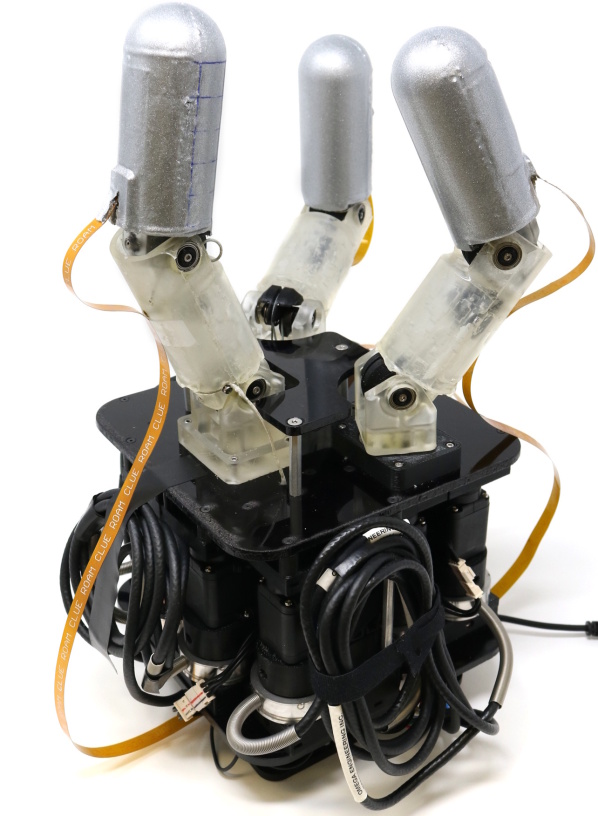
To illustrate the possibility of integration into a complete robot hand, in Figure 8 shows a dexterous robot hand using three fully integrated tactile fingers. Each finger is connected to a control board housed in the palm, which reads all tactile signals from its respective finger, as well as signals from motor encoders and torque sensors. This allows per-finger control based on both tactile and proprioceptive data running directly on the local control board; centralized control for all fingers must run on the computer that combines information from all three boards. However, even in this case, initial processing of the tactile data (e.g., going from 960 signals to contact location and force) can take place on the local control board.
VI-A Limitations
The performance level described above results from using a purely data-driven approach in the form of powerful regression and classification models, which allow us to extract information from a rich signal set without requiring analytical models. However, this approach also comes with inherent limitations. In particular, in order to explicitly predict a given characteristic of touch (such as location or a force component), one must explicitly train a predictor for it, using ground truth data. In the study presented here, this implies the use of an instrumented setup capable of measuring ground truth, and enough time dedicated to the collection of training data.
There are other characteristics of touch that we do not attempt to predict in this study. This includes shear forces due to tangential and torsional friction. Given that, unlike pressure signals, our optical signals sense force indirectly, only through deformation of the light-transporting medium, it is still unclear how sensitive they will be to shear. While other tactile sensors proposed in the literature do provide shear data, many of the most commonly used today do not (e.g., capacitive pressure arrays). Given touch location and normal force (both which our finger provides accurately), we believe that a complete system can partly compensate for the lack of contact shear force data by using torque sensing on the joints of the finger.
The most general way to encode information about a contact patch of arbitrary shape is as a pressure distribution over the entire finger surface. Such a method can generalize to an arbitrary number of simultaneous contacts. However, due to the difficulty of collecting ground truth data for such a predictor, we do not show this ability here. We believe however that the information characterizing a complete contact patch is contained in the rich overlapping optical signal set. This hypothesis is also supported (though not yet fully confirmed) by the ability shown in this study to distinguish multiple touch locations. Future work must thus focus on methods to extract and make use of this information, as we discuss next.
VI-B Implications for future research
When considering future research directions, we start from the premise that a robot tactile finger must ultimately serve as an enabler for robotic manipulation. How does the work presented here fit in this bigger picture?
We believe that are two main avenues for integration of such a tactile finger into a complete manipulation system. First, model-based control and learning methods for manipulation such as Model Predictive Control [53, 54] make direct use of explicitly derived contact properties, such as contact location and force. Under certain conditions (e.g., locally convex objects), we have shown that we can train machine learning models to provide such information with very high accuracy, and over a large functional surface with no blind spots. This can enable a wide range of methods that need this information, e.g., to formulate and solve stability analysis or motion equations for the hand-object system.
The second avenue, one that has recently shown tremendous promise in complex robotic motor control problems, is that of end-to-end, model-free sensorimotor learning [55, 56, 57, 58, 59]. These methods learn a direct mapping from raw sensor data to motor commands. Any intermediate representations of the sensor data are learned at the same time as the task itself, without ground truth other than the general reward signal related to task success. In this context, one would use our sensors to directly train manipulation skills, without the need to collect labeled ground truth for intermediate representations such as contact shape or location. The classifiers and regressors we quantify here serve to illustrate the fact that the raw sensor data indeed comprises rich information pertaining to contact, and suggest the sensor can be used for end-to-end learning.
We plan to explore both of these directions in future work, using the robotic fingers described here. Possible application domains include grasping in extreme clutter (e.g., bin picking or kitting), or in-hand re-orientation of arbitrary objects for assembly tasks. We believe that rich tactile information, in a highly functional form with limited blind spots and a simple integration path into complete systems, will prove to be an important enabler for data-driven complex robotic motor skills, such as dexterous manipulation.
Finger surface parameterization: we use an extension of a projection developed by Roşca[52], which maps a uniform square grid in a two-dimensional space to a near-uniform grid on a half-sphere embedded in three-dimensional space . This parameterization also aims to preserve local areas as much as possible. Note that this space is dimensionless. We use this method directly for the hemispherical section of our finger surface (depicted in red in Fig. 2), which is mapped to a square in space. The equator of the sphere thus corresponds to the outer perimeter of the square, and each side of the square gets mapped to a 90∘ arc along the equator. Formally, a point in the red region of space gets mapped to a Cartesian hemisphere of radius centered at the origin as follows. If :
| (1) | |||||
| (2) |
If
| (3) | |||||
| (4) |
where and is a variable we will use to extend the mapping beyond the tip; for all points on the tip, .
We now extend the mapping beyond the hemispherical tip and onto the cylindrical part of our finger. Starting from the square that maps our sphere, we extend the two sides corresponding to 180∘ of the equator to represent the sensorized area of the cylindrical body. In keeping with the original projection, these new regions are extended such that their areas in match the frontal area of the cylinder. Formally, points in the blue or green regions of space (Fig. 2) are projected into Cartesian space as follows:
| (5) |
| (6) |
| (7) |
where the scaling factor equals the ratio between the real cylinder height and L2 norm of the segment where the green region meets the blue region. The projected values and are plugged back into Eqs. (1-4) to obtain the Cartesian values for points on the cylindrical area of the finger.
Acknowledgment
This work was supported in part by the National Science Foundation under grants CAREER IIS-1551631 and NRI CMMI-1734557.
References
- [1] R. S. Dahiya, G. Metta, M. Valle, and G. Sandini, “Tactile sensing: From humans to humanoids,” IEEE Transactions on Robotics, vol. 26, no. 1, pp. 1–20, 2010.
- [2] M. L. Hammock, A. Chortos, B. C.-K. Tee, J. B.-H. Tok, and Z. Bao, “25th anniversary article: The evolution of electronic skin (e-skin): A brief history, design considerations, and recent progress,” Advanced Materials, vol. 25, no. 42, pp. 5997–6038, 2013.
- [3] A. Chortos and Z. Bao, “Skin-inspired electronic devices,” Materials Today, vol. 17, no. 7, pp. 321–331, 2014.
- [4] Z. Kappassov, J.-A. Corrales, and V. Perdereau, “Tactile sensing in dexterous robot hands - review,” Robotics and Autonomous Systems, vol. 74, pp. 195–220, 2015.
- [5] B. J. Kane, M. R. Cutkosky, and G. T. Kovacs, “A traction stress sensor array for use in high-resolution robotic tactile imaging,” Journal of Microelectromechanical Systems, vol. 9, no. 4, pp. 425–434, 2000.
- [6] H. Takao, K. Sawada, and M. Ishida, “Monolithic silicon smart tactile image sensor with integrated strain sensor array on pneumatically swollen single-diaphragm structure,” IEEE Transactions on Electron Devices, vol. 53, no. 5, pp. 1250–1259, 2006.
- [7] K. Suzuki, K. Najafi, and K. D. Wise, “A 1024-element high-performance silicon tactile imager,” IEEE Transactions on Electron Devices, vol. 37, no. 8, pp. 1852–1860, 1990.
- [8] J. Ulmen and M. Cutkosky, “A robust, low-cost and low-noise artificial skin for human-friendly robots,” in IEEE Intl. Conf. on Robotics and Automation, May 2010, pp. 4836–4841.
- [9] P. Mittendorfer and G. Cheng, “Humanoid multimodal tactile-sensing modules,” IEEE Transactions on Robotics, vol. 27, no. 3, pp. 401–410, June 2011.
- [10] G. H. Buscher, R. Koiva, C. Schurmann, R. Haschke, and H. J. Ritter, “Flexible and stretchable fabric-based tactile sensor,” Robotics and Autonomous Systems, vol. 63, pp. 244–252, 2015.
- [11] C. M. Boutry, M. Negre, M. Jorda, O. Vardoulis, A. Chortos, O. Khatib, and Z. Bao, “A hierarchically patterned, bioinspired e-skin able to detect the direction of applied pressure for robotics,” Science Robotics, vol. 3, no. 24, 2018.
- [12] M. Shimojo, A. Namiki, M. Ishikawa, R. Makino, and K. Mabuchi, “A tactile sensor sheet using pressure conductive rubber with electrical-wires stitched method,” IEEE Sensors, vol. 4, no. 5, pp. 589–596, 2004.
- [13] D.-H. Kim, J.-H. Ahn, W. M. Choi, H.-S. Kim, T.-H. Kim, J. Song, Y. Y. Huang, Z. Liu, C. Lu, and J. A. Rogers, “Stretchable and foldable silicon integrated circuits,” Science, vol. 320, no. 5875, 2008.
- [14] J. Byun, Y. Lee, J. Yoon, B. Lee, E. Oh, S. Chung, T. Lee, K.-J. Cho, J. Kim, and Y. Hong, “Electronic skins for soft, compact, reversible assembly of wirelessly activated fully soft robots,” Science Robotics, vol. 3, 2018.
- [15] L. E. Osborn, A. Dragomir, J. L. Betthauser, C. L. Hunt, H. H. Nguyen, R. R. Kaliki, and N. V. Thakor, “Prosthesis with neuromorphic multilayered e-dermis perceives touch and pain,” Science Robotics, vol. 3, 2018.
- [16] Y. Wu, Y. Liu, Y. Zhou, Q. Man, C. Hu, W. Asghar, F. Li, Z. Yu, J. Shang, G. Liu1, M. Liao, and R.-W. Li, “A skin-inspired tactile sensor for smart prosthetics,” Science Robotics, vol. 3, 2018.
- [17] A. Drimus, G. Kootstra, A. Bilberg, and D. Kragic, “Design of a flexible tactile sensor for classification of rigid and deformable objects,” Robotics and Autonomous Systems, vol. 62, no. 1, pp. 3–15, 2014.
- [18] S. Begej, “Planar and finger-shaped optical tactile sensors for robotic applications,” IEEE Journal on Robotics and Automation, vol. 4, no. 5, pp. 472–484, 1988.
- [19] F. Schneider, J. Draheim, R. Kamberger, and U. Wallrabe, “Process and material properties of polydimethylsiloxane (pdms) for optical mems,” Sensors and Actuators A: Physical, vol. 151, no. 2, pp. 95–99, 2009.
- [20] W. Li, J. Konstantinova, Y. Noh, Z. Ma, A. Alomainy, and K. Althoefer, “An elastomer-based flexible optical force and tactile sensor,” in IEEE Intl. Conf. on Soft Robotics (RoboSoft). IEEE, 2019, pp. 361–366.
- [21] M. K. Johnson and E. H. Adelson, “Retrographic sensing for the measurement of surface texture and shape,” in IEEE Conf. on Computer Vision and Pattern Recognition, 2009, pp. 1070–1077.
- [22] N. F. Lepora and B. Ward-Cherrier, “Superresolution with an optical tactile sensor,” in IEEE/RSJ Intl. Conf. on Intelligent Robots and Systems. IEEE, 2015, pp. 2686–2691.
- [23] D. Ma, E. Donlon, S. Dong, and A. Rodriguez, “Dense tactile force estimation using gelslim and inverse fem,” in Intl. Conf. on Robotics and Automation. IEEE, 2019, pp. 5418–5424.
- [24] P. Polygerinos, D. Zbyszewski, T. Schaeffter, R. Razavi, L. D. Seneviratne, and K. Althoefer, “Mri-compatible fiber-optic force sensors for catheterization procedures,” IEEE Sensors, vol. 10, no. 10, pp. 1598–1608, 2010.
- [25] J. Konstantinova, A. Stilli, and K. Althoefer, “Fingertip fiber optical tactile array with two-level spring structure,” Sensors, vol. 17, no. 10, p. 2337, 2017.
- [26] A. Levi, M. Piovanelli, S. Furlan, B. Mazzolai, and L. Beccai, “Soft, transparent, electronic skin for distributed and multiple pressure sensing,” Sensors, vol. 13, no. 5, pp. 6578–6604, 2013.
- [27] S. Yun, S. Park, B. Park, Y. Kim, S. K. Park, S. Nam, and K.-U. Kyung, “Polymer-waveguide-based flexible tactile sensor array for dynamic response,” Advanced materials, vol. 26, no. 26.
- [28] M. Quigley, C. Salisbury, A. Y. Ng, and J. K. Salisbury, “Mechatronic design of an integrated robotic hand,” The Intl. Journal of Robotics Research, vol. 33, no. 5, pp. 706–720, 2014.
- [29] R. Patel, R. E. Cox, and N. Correll, “Integrated force and distance sensing using elastomer-embedded commodity proximity sensors.” Sandia National Lab, Albuquerque, NM, Tech. Rep., 2017.
- [30] I. Van Meerbeek, C. De Sa, and R. Shepherd, “Soft optoelectronic sensory foams with proprioception,” Science Robotics, vol. 3, no. 24, p. 2489, 2018.
- [31] A. Nagakubo, H. Alirezaei, and Y. Kuniyoshi, “A deformable and deformation sensitive tactile distribution sensor,” in Intl. Conf. on Robotics and Biomimetics. IEEE, 2007, pp. 1301–1308.
- [32] Y. Kato, T. Mukai, T. Hayakawa, and T. Shibata, “Tactile sensor without wire and sensing element in the tactile region based on eit method,” in Sensors. IEEE, 2007, pp. 792–795.
- [33] D. S. Tawil, D. Rye, and M. Velonaki, “Improved image reconstruction for an eit-based sensitive skin with multiple internal electrodes,” IEEE Transactions on Robotics, vol. 27, no. 3, pp. 425–435, 2011.
- [34] H. Lee, D. Kwon, H. Cho, I. Park, and J. Kim, “Soft nanocomposite based multi-point, multi-directional strain mapping sensor using anisotropic electrical impedance tomography,” Scientific Reports, vol. 7, p. 39837, 2017.
- [35] D. Silvera-Tawil, D. Rye, M. Soleimani, and M. Velonaki, “Electrical impedance tomography for artificial sensitive robotic skin: A review,” IEEE Sensors Journal, vol. 15, no. 4, pp. 2001–2016, 2015.
- [36] D. J. van den Heever, K. Schreve, and C. Scheffer, “Tactile sensing using force sensing resistors and a super-resolution algorithm,” IEEE Sensors Journal, vol. 9, no. 1, pp. 29–35, 2009.
- [37] N. F. Lepora, U. Martinez-Hernandez, M. Evans, L. Natale, G. Metta, and T. J. Prescott, “Tactile superresolution and biomimetic hyperacuity,” IEEE Transactions on Robotics, vol. 31, no. 3, pp. 605–618, 2015.
- [38] L. Muscari, L. Seminara, F. Mastrogiovanni, M. Valle, M. Capurro, and G. Cannata, “Real-time reconstruction of contact shapes for large area robot skin,” in Intl. Conf. on Robotics and Automation. IEEE, 2013, pp. 2360–2366.
- [39] K. Hosoda, Y. Tada, and M. Asada, “Anthropomorphic robotic soft fingertip with randomly distributed receptors,” Robotics and Autonomous Systems, vol. 54, pp. 104–109, 02 2006.
- [40] N. Wettels, V. J. Santos, R. S. Johansson, and G. E. Loeb, “Biomimetic tactile sensor array,” Advanced Robotics, vol. 22, no. 8.
- [41] J. W. Booth, D. Shah, J. C. Case, E. L. White, M. C. Yuen, O. Cyr-Choiniere, and R. Kramer-Bottiglio, “Omniskins: Robotic skins that turn inanimate objects into multifunctional robots,” Science Robotics, vol. 3, no. 22, 2018.
- [42] F. R. Hogan, M. Bauza, O. Canal, E. Donlon, and A. Rodriguez, “Tactile regrasp: Grasp adjustments via simulated tactile transformations,” in Intl. Conf. on Intelligent Robots and Systems. IEEE, 2018, pp. 2963–2970.
- [43] M. Li, Y. Bekiroglu, D. Kragic, and A. Billard, “Learning of grasp adaptation through experience and tactile sensing,” in Intl. Conf. on Intelligent Robots and Systems. IEEE, 2014, pp. 3339–3346.
- [44] H. Dang and P. K. Allen, “Grasp adjustment on novel objects using tactile experience from similar local geometry,” in 2013 IEEE/RSJ Intl. Conf. on Intelligent Robots and Systems. IEEE, 2013, pp. 4007–4012.
- [45] M. Meier, F. Patzelt, R. Haschke, and H. J. Ritter, “Tactile convolutional networks for online slip and rotation detection,” in Intl. Conf. on Artificial Neural Networks. Springer, 2016, pp. 12–19.
- [46] R. D. P. Wong, R. B. Hellman, and V. J. Santos, “Haptic exploration of fingertip-sized geometric features using a multimodal tactile sensor,” in Next-Generation Robots and Systems, vol. 9116. Intl. Society for Optics and Photonics, 2014, p. 911605.
- [47] Q. Wan, R. P. Adams, and R. Howe, “Variability and predictability in tactile sensing during grasping,” in IEEE Intl. Conf. on Robotics and Automation. IEEE, 2016, pp. 158–164.
- [48] Y. Tenzer, L. P. Jentoft, and R. D. Howe, “The feel of mems barometers: Inexpensive and easily customized tactile array sensors,” IEEE Robotics & Automation Magazine, vol. 21, no. 3, pp. 89–95, 2014.
- [49] T. G. Thuruthel, B. Shih, C. Laschi, and M. T. Tolley, “Soft robot perception using embedded soft sensors and recurrent neural networks,” Science Robotics, vol. 4, no. 26, 2019.
- [50] D. S. Tawil, D. Rye, and M. Velonaki, “Touch modality interpretation for an eit-based sensitive skin,” in IEEE Intl. Conf. on Robotics and Automation. IEEE, 2011, pp. 3770–3776.
- [51] P. Piacenza, W. Dang, E. Hannigan, J. Espinal, I. Hussain, I. Kymissis, and M. Ciocarlie, “Accurate contact localization and indentation depth prediction with an optics-based tactile sensor,” in IEEE Intl. Conf. on Robotics and Automation. IEEE, 2017, pp. 959–965.
- [52] D. Roşca, “New uniform grids on the sphere,” Astronomy & Astrophysics, vol. 520, p. A63, 2010.
- [53] E. Todorov and W. Li, “A generalized iterative lqg method for locally-optimal feedback control of constrained nonlinear stochastic systems,” in American Control Conf. IEEE, 2005, pp. 300–306.
- [54] T. Erez, Y. Tassa, and E. Todorov, “Infinite-horizon model predictive control for periodic tasks with contacts,” Robotics: Science and systems VII, p. 73, 2012.
- [55] S. Levine, N. Wagener, and P. Abbeel, “Learning contact-rich manipulation skills with guided policy search,” in IEEE Intl. Conf. on Robotics and Automation, 2015.
- [56] S. Levine, P. Pastor, A. Krizhevsky, and D. Quillen, “Learning hand-eye coordination for robotic grasping with large-scale data collection,” in Intl. Symposium on Experimental Robotics.
- [57] F. Sadeghi and S. Levine, “CAD2RL: Real single-image flight without a single real image,” CoRR, vol. abs/1611.04201, 2016.
- [58] X. B. Peng, M. Andrychowicz, W. Zaremba, and P. Abbeel, “Sim-to-real transfer of robotic control with dynamics randomization,” CoRR, vol. abs/1710.06537, 2017.
- [59] M. Andrychowicz, B. Baker, M. Chociej, R. Jozefowicz, B. McGrew, J. Pachocki, A. Petron, M. Plappert, G. Powell, A. Ray, J. Schneider, S. Sidor, J. Tobin, P. Welinder, L. Weng, and W. Zaremba, “Learning dexterous in-hand manipulation,” CoRR, vol. abs/1808.00177, 2018.
![[Uncaptioned image]](/html/2004.00685/assets/images/BIO1.jpg) |
Pedro Piacenza is a Ph.D. candidate at Columbia University. He obtained his M.S. from Columbia University, and his B.S. in Electrical Engineering from Universidad Catolica Argentina. His research focuses on developing tactile feedback systems for robotic manipulation. |
![[Uncaptioned image]](/html/2004.00685/assets/images/BIO2.jpg) |
Keith Behrman is a Ph.D. candidate in the Columbia Lab for Unconventional Electronics (CLUE) at Columbia University. He obtained his M.S from Columbia and his B.S. in Physics from The University of Minnesota. His research is focused in micro-LED devices for next-generation display systems. |
![[Uncaptioned image]](/html/2004.00685/assets/images/BIO3.jpg) |
Benedikt Schifferer is an M.S. candidate in Data Science at Columbia University. He obtained his BSc. in Mathematics and Business Administration at the University of Mannheim. |
![[Uncaptioned image]](/html/2004.00685/assets/images/BIO4.jpg) |
Ioannis Kymissis is Professor in the Electrical Eng. Dept. at Columbia University. He obtained his S.B., M.Eng. and Ph.D. degrees from MIT, and also participated in a cooperative program through which he completed his M.Eng. thesis at IBM Research. His research focuses on fabrication and characterization of thin film electronics. |
![[Uncaptioned image]](/html/2004.00685/assets/images/BIO5.jpg) |
Matei Ciocarlie is Associate Professor at Columbia University. He completed his Ph.D. and M.S. degrees at Columbia University, and his B.S. at the Polytechnic University of Bucharest. His main research interest is in reliable robotic performance in unstructured, human environments, looking to discover how artificial mechanisms can interact with the world as skillfully as biological organisms. |