Stabilizing chiral spin-structures via an alternating Dzyaloshinskii–Moriya interaction
Abstract
The stabilization of chiral magnetic spin-structures in thin films is often attributed to the interfacial Dzyaloshinskii–Moriya interaction (DMI). Very recently, however, it has been reported that the chirality induced by the DMI can be affected by dipolar interactions. These dipolar fields tend to form Néel caps, which entails the formation of a clockwise chirality at the top of the film and a counterclockwise chirality at the bottom. Here, we show that engineering an alternating DMI that changes sign across the film thickness, together with the tendency to form Neel caps, leads to an enhanced stability of chiral spin-structures. Micromagnetic simulations for skyrmions demonstrate that this can increase the effective DMI in a prototypical [Pt/Co/Ir] multilayer system by at least . These gains are comparable to what has been achieved using additive DMI, but more flexible as we are not limited to a select set of material combinations. We also present experimental results: by measuring equilibrium domain widths we quantify the effective DMI in [Pt/Co/Ir] multilayer systems typically used for skyrmion stabilization. Upon introducing an alternating DMI we demonstrate changes in the effective DMI that agree with our simulations. Our results provide a route towards enhancing the stability of chiral spin-structures that does not rely on enlarging the chiral interactions.
Magnetic skyrmions are whirling chiral spin-structures that can be as small as a few . Nagaosa and Tokura (2013); Wiesendanger (2016); Fert et al. (2017); Everschor-Sitte et al. (2018) Because of their topological protection, they are extremely stable magnetic quasiparticles that might find their use in many applications such as magnetic racetrack memory. Nagaosa and Tokura (2013); Rohart et al. (2016); Fert et al. (2017); Wiesendanger (2016); Everschor-Sitte et al. (2018); Fert et al. (2013) Skyrmions are typically stabilized by the Dzyaloshinskii–Moriya interaction (DMI), which originates from a global inversion symmetry breaking in combination with spin-orbit coupling. Moriya (1960); Dzyaloshinsky (1958) Although skyrmions exist in many systems, Mühlbauer et al. (2009); Yu et al. (2010); Heinze et al. (2011); Wiesendanger (2016); Woo et al. (2016); Moreau-Luchaire et al. (2016); Boulle et al. (2016) there is a great interest in skyrmions stabilized in ultra-thin ferromagnets. Their stabilization is achieved through the interfacial DMI from a symmetry-breaking interface between an ultra-thin ferromagnet and a heavy metal. Bogdanov and Rößler (2001); Fert (1991); Crépieux and Lacroix (1998) In these ultrathin systems, the magnetic properties can be tailored for specific applications by varying the magnetic layer thicknesses and interfaces.
Unfortunately, the DMI is often not large enough to stabilize magnetic skyrmions at room temperature. To compensate for this, the magnetic volume is usually increased to enhance the thermal stability and reduce the skyrmion energy. Woo et al. (2016); Moreau-Luchaire et al. (2016); Boulle et al. (2016); Soumyanarayanan et al. (2017) The concomitant increase of dipolar interactions, however, has been shown both theoretically and experimentally to compete with the DMI leading to a non-uniform magnetic chirality across the thickness of the layers. Hubert and Schäfer (1998); Lucassen et al. (2019); Li et al. (2019); Garlow et al. (2019); Montoya et al. (2017); Legrand et al. (2018a); Lemesh and Beach (2018); Legrand et al. (2018b); Dovzhenko et al. (2018); Fallon et al. (2019) This is considered detrimental for applications because most of the functionality relies on the uniform chirality of a skyrmion across the thickness of the multilayer system.111As the chirality of the skyrmions varies between individual repeats of the multilayer system these are not skyrmions in the strictest sense. Nagaosa and Tokura (2013); Wiesendanger (2016); Fert et al. (2017); Everschor-Sitte et al. (2018)
On the other hand, despite their negative effect on the magnetic chirality, even without the DMI dipolar interactions are able to stabilize so-called dipolar skyrmions. Hrabec et al. (2017); Bellec et al. (2010); Meijer et al. (2019) This occurs through the formation of Néel caps, which is the formation of a clockwise chirality at the top of the film and a counterclockwise chirality at the bottom. Inspired by this, we suggest here to combine the formation of Néel caps with a layer-dependent alternating DMI to enhance the stability of chiral spin-structures as is shown schematically in Fig. 1a for a magnetic domain wall. The dipolar fields introduce Néel caps with a clockwise (CW) Néel wall at the top of the film, and a counterclockwise (CCW) Néel wall at the bottom. For a uniform DMI this leads to a competition with the DMI across half the stack. Therefore, we intentionally reverse the sign of the DMI halfway through the system, such that in both halves of the stack the DMI field points in the same direction as the dipolar fields, which leads to a reduction in both the domain wall and skyrmion energy. In the first part of this Letter, we investigate this principle using MuMax3 based micromagnetic simulations Vansteenkiste et al. (2014) and demonstrate that it leads to significant increases in the effective DMI by comparing skyrmion energies for different DMI configurations. Thereafter, we also present experimental results on the effect of modifying the DMI in a multilayer [Pt/Co/Ir] system. Upon changing the DMI configuration we find almost a factor increase in the effective DMI after accounting for growth-induced variations in the magnetic parameters through an averaging approach, which we verify with micromagnetic simulations. This proves that Néel caps can be exploited to significantly increase the stability of chiral spin-structures and opens up a way to tailor them by modifying magnetic interactions on a layer-by-layer basis.
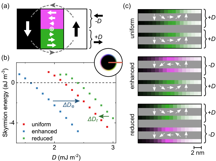
We investigate the behaviour of confined magnetic skyrmions in a diameter circular dot (inset Fig. 1b) with MuMax3 using [NM()/FM()]x systems, with repeats of a thick ferromagnetic layer (FM) sandwiched in between thick non-magnetic (NM) spacer layers. The magnetic parameters used for these calculations correspond to the experimental parameters of the prototypical [Pt/Co/Ir] systems experimentally investigated later in this Letter. More details on the simulations can be found in supplementary note I. In Fig. 1b the energy of the skyrmion state with respect to the uniformly magnetized state is plotted as a function of the DMI for different DMI configurations which are indicated in Fig. 1c: i) a uniform configuration, where the DMI is equal across all layers, ii) an enhanced DMI configuration, where the sign of the DMI aligns along the internal dipolar fields everywhere in the stack, and iii) a reduced DMI configuration where the sign of the DMI is always aligned anti-parallel to the dipolar fields. The enhanced and reduced DMI configurations lead to the formation of a thickness dependent chirality by the introduction of Néel caps. For all DMI configurations, the skyrmion energy decreases with increasing DMI as expected. In addition, the enhanced DMI configuration leads to a significantly reduced skyrmion energy, and the reduced configuration to an increase in the skyrmion energy. This is completely in line with the simple picture sketched in Fig. 1a. Specifically, as indicated in Fig. 1b with the DMI gain , the required to obtain a skyrmion whose energy is lower than the uniformly magnetized state decreases by upon introducing the enhanced configuration. This is a massive increase in stability and comparable in magnitude to the gains obtained when utilizing an effect like additive DMI. Moreau-Luchaire et al. (2016); Soumyanarayanan et al. (2017); Yang et al. (2018) Moreover, as we are not bound to the small set of material systems with a large additive DMI this should be more widely applicable. In supplementary note II we additionally show that while does vary with , the presented behaviour remains qualitatively identical.
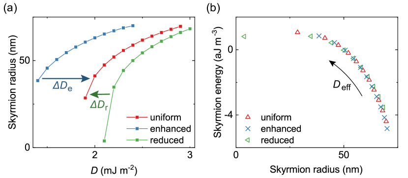
Introducing these different DMI configurations also has a profound effect on the skyrmion radius as shown in Fig. 2a.222In supplementary note III we also show the results for the simulations under an applied magnetic field, where the enhanced DMI configuration leads to a larger field stability. In agreement with the results found in literature, an increase in leads to an increase in the skyrmion radius. Rohart and Thiaville (2013); Moreau-Luchaire et al. (2016) We can understand this by thinking of a skyrmion as an out-of-plane (OOP) magnetized core enclosed by a domain wall. Romming et al. (2015); Rohart and Thiaville (2013) As increases the domain wall energy decreases, resulting in a skyrmion that can expand to enhance the dipolar coupling of the core to the annulus. The same mechanism explains the behaviour for the three different DMI configurations; the skyrmion becomes bigger (smaller) when introducing the enhanced (reduced) DMI configuration because the domain wall energy decreases (increases). In supplementary note IV we further illustrate that the confinement effect of the simulated dot does not qualitatively affect the presented behaviour.
We will now try to understand the effect of the different DMI configurations in a more general way. Combined, the behaviour depicted in Fig. 1b and Fig. 2a suggests some form of universality. All the curves show qualitatively the same behaviour as a function of , apart from the shifted values indicated by the arrows of DMI gain () and loss (). This can be understood by considering the effect of the dipolar fields: as suggested by Lemesh et al., Lemesh and Beach (2018) the dipolar fields can be included as an effective DMI because both components introduce an effective in-plane magnetic field in the domain wall. We can thus introduce an effective DMI (see Fig. 1b) for the enhanced and reduced configurations. In this specific case, the enhanced configuration behaves as a system with an effective DMI that is larger than the DMI because of the additive effects of the DMI and dipolar interactions. Conversely, the reduced configuration has a smaller effective DMI with . A consequence of this universality is shown in Fig. 2b, where the skyrmion energy is plotted as a function of skyrmion radius for the three different DMI configurations. The simulations for the different DMI configurations collapse on the same curve. Thus, although for each configuration the needed to obtain a particular energy/radius is different, the relationship between the two remains unaffected and can be described by an that has a DMI-configuration dependent contribution. Last, in supplementary note V we demonstrate that the introduction of Néel caps can in some cases lead to non-circular skyrmions to accommodate both the DMI and dipolar interactions.
In the previous paragraphs we have introduced the unique ability of a layer-dependent DMI configuration to enhance the stability of skyrmions. This part presents experimental evidence which shows that can be tailored by modifying the DMI on a layer-by-layer basis. To demonstrate this, instead of skyrmions we shift our attention to domain walls for their much easier experimental access, and their fully analogous underlying physics. They allow us to accurately quantify because the domain width in magnetic multilayers is determined by the competition between the domain wall energy and dipolar interactions between the domains. Draaisma and De
Jonge (1987); Suna (1986); Lemesh et al. (2017); Boulle et al. (2016); Moreau-Luchaire et al. (2016); Woo et al. (2016); Lemesh and Beach (2018); Legrand et al. (2018a) Here, we use the accurate stripe domain model by Lemesh et al. Lemesh et al. (2017) to determine in four different Ta()/Pt()/X/Ta() systems (thicknesses in parentheses in ) to investigate the effect of the different DMI configurations. X for each stack is given by:
Uniform I: x,
Uniform II: x,
Enhanced: xx,
Reduced: xx.
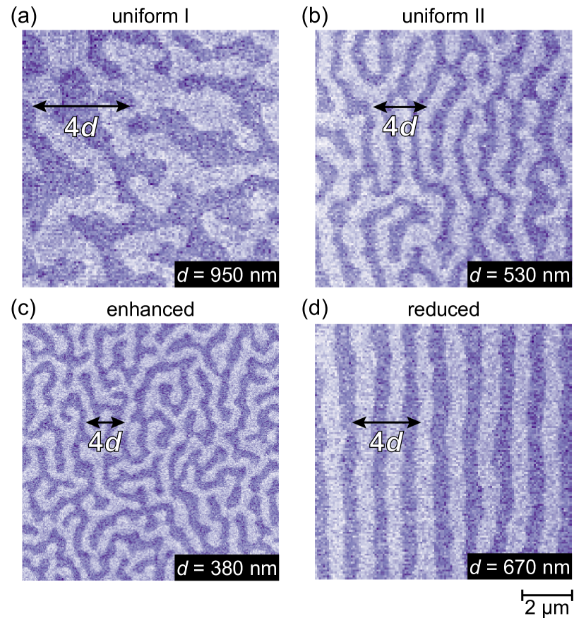
Pt and Ir were chosen because of their opposite interfacial DMI signs such that they favour CCW Néel walls for a Pt/Co/Ir stacking () and CW Néel walls for an Ir/Co/Pt stacking (). Ma et al. (2018); Tacchi et al. (2017); Han et al. (2016); Finizio et al. (2019); Moreau-Luchaire et al. (2016) The two different uniform stacks were fabricated to investigate the contributions of the stacking order. In Fig. 3 the resulting domain patterns after demagnetization are shown. These were recorded using magnetic force microscopy (MFM) measurements and the domain width was extracted through a Fourier analysis. The experimental details can be found in supplementary note I.
| () | () | () | () | |
| Uniform I | ||||
| Uniform II | ||||
| Uniform averaged | - | |||
| Enhanced | ||||
| Reduced |
We start our discussion of the experimental results by looking at the enhanced and reduced configuration. For the enhanced configuration we would expect a larger compared to reduced configuration because of the additive effect of the DMI and the dipolar interactions. From the measured domain widths we calculate and show this in Table 1. Lemesh et al. (2017) Indeed, is larger for the enhanced configuration () compared to the reduced configuration (). As suggested earlier, this possibly results from the modified DMI ordering in combination with the dipolar interactions that lead to Néel caps.
There is another element that we have to account for in this analysis: the effect of the stacking order of the layers. For both uniform configurations, should be equal as we have simply inverted the stacking order. However, as we calculate from the measured we find that it varies by a factor of for the uniform I and II configurations as is shown in Table 1. Moreover, there is also significant variation in the measured saturation magnetization and anisotropy for these configurations. From this we conclude that the magnetic parameters for [Pt/Co/Ir] and [Ir/Co/Pt] vary significantly because of growth-related effects stemming from the stacking order. This seriously complicates the comparison between the different DMI configurations.
To still be able to compare the different DMI configurations, we need to extract the actual values for the enhanced and reduced configurations to conclude if there is an increase in for these systems. For this, we account for the growth-induced variations quantitatively by performing micromagnetic simulations in supplementary note VI. In these simulations we compare the domain wall energies in the enhanced and reduced stack with layer-dependent magnetic parameters, to a stack with the averaged parameters of both uniform stacks. From this we conclude that a hypothetical stack with these averaged magnetic parameters is a good approximation of the experimental situation, leading to errors in . To calculate for the enhanced and reduced configuration we can therefore simply average the of both uniform configurations, which we have also included in Table 1. We now compare of the averaged stack () to both the enhanced and reduced stack, we find that the absolute increase of the enhanced configuration (+), and decrease of the reduced configuration () agree reasonably well with the values predicted in Fig. 1b of + and . Despite the growth-related complications when the building blocks of our stacks are reversed, we believe that our experimental results convincingly demonstrate that changing the sign of the DMI halfway through the stack leads to significant changes in . Finally, in supplementary note VII we present experimental results for an system, with similar variations in as the system proving the wide applicability of our approach.
Summarizing the experimental part, we found changing the sign of the DMI halfway through a multilayer system is a powerful method to increase the effective DMI. With the relatively modest increase in of the enhanced configuration () compared to the uniform I configuration () there is still room for improvement. The largest benefit of the enhanced DMI configuration will be found in a system with a large DMI where the growth-induced variations between the opposite stacking orders are small. As there are a host of different interface combinations with a large DMI, we expect there to be many material combinations that fit this pattern.
We would now like to comment on two aspects of exploiting the Néel caps to stabilize chiral spin-structures. First, the introduction of an enhanced DMI configuration does not affect the skyrmion dynamics. Although the resulting vanishing total interfacial chirality suggests that spin-orbit torques can no longer be used to drive skyrmion dynamics, this is not true for the proposed experimental stacks of [Pt/Co/Ir] and [Ir/Co/Pt]. Legrand et al. (2018a); Lemesh and Beach (2018); Legrand et al. (2018b); Montoya et al. (2018) When changing the stacking order halfway through the stack, it is not only the interfacial chirality, but also the local spin-orbit torques from the individual Pt and Ir layers that are reversed. Manchon et al. (2019) In this case, the spin-orbit torques acting on the skyrmion are the same for both halves of the stacks, ensuring skyrmions can still be driven efficiently using an electrical current. As there are also indications that an enhanced DMI configuration can postpone the Walker-breakdown-like behaviour for both domain walls and skyrmions to much higher current densities, Lemesh and Beach (2019) it is therefore interesting to explore their dynamics in the case of an enhanced DMI configuration in more detail.
Second, more ideas exist that make use of dipolar interactions and magnetic parameters that vary on a layer-by-layer basis. For example, by modifying the anisotropy, one might be able to increase the domain wall width at the top and bottom of the film to enhance the coupling with the dipolar fields and increase the skyrmion stability even further. Or, one could imagine changing the position within the stack where the DMI reverses, and thus the point at which the chirality reverses, to, for example, reduce the skyrmion Hall angle. Legrand et al. (2018b) Perhaps it is even possible to stabilize more complex three-dimensional spin-structures such as the magnetic hopfion or skyrmion bobber by modifying individual magnetic parameters on a layer-by-layer basis. Wang et al. (2019); Tai and Smalyukh (2018); Sutcliffe (2018)
In conclusion, using micromagnetic simulations we have shown that the stability of chiral spin-structures in multilayer systems can be significantly enhanced by exploiting the presence of Néel caps. This can be by introducing an alternating DMI in a multilayer system, leading to increases in the effective DMI of at least . We have also shown experimental results in this direction, where we find variations in the effective DMI that agree with our predictions. These results open the way to alternative methods for the stabilization of chiral spin-structures by tailoring the magnetic interactions on a layer-by-layer basis.
Acknowledgements.
This work is part of the research programme of the Foundation for Fundamental Research on Matter (FOM), which is part of the Netherlands Organisation for Scientific Research (NWO).References
- Nagaosa and Tokura (2013) N. Nagaosa and Y. Tokura, Nat. Nanotechnol. 8, 899 (2013).
- Wiesendanger (2016) R. Wiesendanger, Nat. Rev. Mater. 1, 16044 (2016).
- Fert et al. (2017) A. Fert, N. Reyren, and V. Cros, Nat. Rev. Mater. 2, 17031 (2017).
- Everschor-Sitte et al. (2018) K. Everschor-Sitte, J. Masell, R. M. Reeve, and M. Kläui, J. Appl. Phys. 124, 240901 (2018).
- Rohart et al. (2016) S. Rohart, J. Miltat, and A. Thiaville, Phys. Rev. B 93, 214412 (2016).
- Fert et al. (2013) A. Fert, V. Cros, and J. Sampaio, Nat. Nanotechnol. 8, 152 (2013).
- Moriya (1960) T. Moriya, Phys. Rev. 120, 91 (1960).
- Dzyaloshinsky (1958) I. Dzyaloshinsky, J. Phys. Chem. Solids 4, 241 (1958).
- Mühlbauer et al. (2009) S. Mühlbauer, B. Binz, F. Jonietz, C. Pfleiderer, A. Rosch, A. Neubauer, R. Georgii, and P. Böni, Science 323, 915 (2009).
- Yu et al. (2010) X. Z. Yu, Y. Onose, N. Kanazawa, J. H. Park, J. H. Han, Y. Matsui, N. Nagaosa, and Y. Tokura, Nature 465, 901 (2010).
- Heinze et al. (2011) S. Heinze, K. von Bergmann, M. Menzel, J. Brede, A. Kubetzka, R. Wiesendanger, G. Bihlmayer, and S. Blügel, Nat. Phys. 7, 713 (2011).
- Woo et al. (2016) S. Woo, K. Litzius, B. Krüger, M.-Y. Im, L. Caretta, K. Richter, M. Mann, A. Krone, R. M. Reeve, M. Weigand, P. Agrawal, I. Lemesh, M.-A. Mawass, P. Fischer, M. Kläui, and G. S. D. Beach, Nat. Mater. 15, 501 (2016).
- Moreau-Luchaire et al. (2016) C. Moreau-Luchaire, C. Moutafis, N. Reyren, J. Sampaio, C. A. F. Vaz, N. Van Horne, K. Bouzehouane, K. Garcia, C. Deranlot, P. Warnicke, P. Wohlhüter, J.-M. George, M. Weigand, J. Raabe, V. Cros, and A. Fert, Nat. Nanotechnol. 11, 444 (2016).
- Boulle et al. (2016) O. Boulle, J. Vogel, H. Yang, S. Pizzini, D. d. S. Chaves, A. Locatelli, T. O. M. A. Sala, L. D. Buda-Prejbeanu, O. Klein, M. Belmeguenai, Y. Roussigné, A. Stashkevich, S. M. Chérif, L. Aballe, M. Foerster, M. Chshiev, S. Auffret, I. M. Miron, and G. Gaudin, Nat. Nanotechnol. 11, 449 (2016).
- Bogdanov and Rößler (2001) A. N. Bogdanov and U. K. Rößler, Phys. Rev. Lett. 87, 037203 (2001).
- Fert (1991) A. Fert, in Metallic Multilayers, Materials Science Forum, Vol. 59 (Trans Tech Publications Ltd, 1991) pp. 439–480.
- Crépieux and Lacroix (1998) A. Crépieux and C. Lacroix, J. Magn. Magn. Mater. 182, 341 (1998).
- Soumyanarayanan et al. (2017) A. Soumyanarayanan, M. Raju, A. L. Gonzalez Oyarce, A. K. C. Tan, M.-Y. Im, A. P. Petrovic, P. Ho, K. H. Khoo, M. Tran, C. K. Gan, F. Ernult, and C. Panagopoulos, Nat. Mat. 16, 898 (2017).
- Hubert and Schäfer (1998) A. Hubert and R. Schäfer, Magnetic Domains : the Analysis of Magnetic Microstructures, 1st ed. (Springer-Verlag Berlin Heidelberg, New York, 1998) pp. 240–241.
- Lucassen et al. (2019) J. Lucassen, M. J. Meijer, O. Kurnosikov, H. J. M. Swagten, B. Koopmans, R. Lavrijsen, F. Kloodt-Twesten, R. Frömter, and R. A. Duine, Phys. Rev. Lett. 123, 157201 (2019).
- Li et al. (2019) W. Li, I. Bykova, S. Zhang, G. Yu, R. Tomasello, M. Carpentieri, Y. Liu, Y. Guang, J. Gräfe, M. Weigand, D. M. Burn, G. van der Laan, T. Hesjedal, Z. Yan, J. Feng, C. Wan, J. Wei, X. Wang, X. Zhang, H. Xu, C. Guo, H. Wei, G. Finocchio, X. Han, and G. Schütz, Adv. Mater. 31, 1807683 (2019).
- Garlow et al. (2019) J. A. Garlow, S. D. Pollard, M. Beleggia, T. Dutta, H. Yang, and Y. Zhu, Phys. Rev. Lett. 122, 237201 (2019).
- Montoya et al. (2017) S. A. Montoya, S. Couture, J. J. Chess, J. C. T. Lee, N. Kent, D. Henze, S. K. Sinha, M.-Y. Im, S. D. Kevan, P. Fischer, B. J. McMorran, V. Lomakin, S. Roy, and E. E. Fullerton, Phys. Rev. B 95, 024415 (2017).
- Legrand et al. (2018a) W. Legrand, J.-Y. Chauleau, D. Maccariello, N. Reyren, S. Collin, K. Bouzehouane, N. Jaouen, V. Cros, and A. Fert, Sci. Adv. 4 (2018a).
- Lemesh and Beach (2018) I. Lemesh and G. S. D. Beach, Phys. Rev. B 98, 104402 (2018).
- Legrand et al. (2018b) W. Legrand, N. Ronceray, N. Reyren, D. Maccariello, V. Cros, and A. Fert, Phys. Rev. Applied 10, 064042 (2018b).
- Dovzhenko et al. (2018) Y. Dovzhenko, F. Casola, S. Schlotter, T. X. Zhou, F. Büttner, R. L. Walsworth, G. S. D. Beach, and A. Yacoby, Nat. Comm. 9, 2712 (2018).
- Fallon et al. (2019) K. Fallon, S. McVitie, W. Legrand, F. Ajejas, D. Maccariello, S. Collin, V. Cros, and N. Reyren, Phys. Rev. B 100, 214431 (2019).
- Hrabec et al. (2017) A. Hrabec, J. Sampaio, M. Belmeguenai, I. Gross, R. Weil, S. M. Chérif, A. Stashkevich, V. Jacques, A. Thiaville, and S. Rohart, Nat. Comm. 8, 15765 (2017).
- Bellec et al. (2010) A. Bellec, S. Rohart, M. Labrune, J. Miltat, and A. Thiaville, EPL 91, 17009 (2010).
- Meijer et al. (2019) M. J. Meijer, J. Lucassen, F. Kloodt-Twesten, R. Frömter, O. Kurnosikov, R. A. Duine, H. J. M. Swagten, B. Koopmans, and R. Lavrijsen, arXiv e-prints , arXiv:1909.08909 (2019), arXiv:1909.08909 [cond-mat.mes-hall] .
- Vansteenkiste et al. (2014) A. Vansteenkiste, J. Leliaert, M. Dvornik, M. Helsen, F. Garcia-Sanchez, and B. Van Waeyenberge, AIP Adv. 4, 107133 (2014).
- Yang et al. (2018) H. Yang, O. Boulle, V. Cros, A. Fert, and M. Chshiev, Sci. Rep. 8, 12356 (2018).
- Rohart and Thiaville (2013) S. Rohart and A. Thiaville, Phys. Rev. B 88, 184422 (2013).
- Romming et al. (2015) N. Romming, A. Kubetzka, C. Hanneken, K. von Bergmann, and R. Wiesendanger, Phys. Rev. Lett. 114, 177203 (2015).
- Draaisma and De Jonge (1987) H. J. G. Draaisma and W. J. M. De Jonge, J. Appl. Phys. 62, 3318 (1987).
- Suna (1986) A. Suna, J. Appl. Phys. 59, 313 (1986).
- Lemesh et al. (2017) I. Lemesh, F. Büttner, and G. S. D. Beach, Phys. Rev. B 95, 174423 (2017).
- Ma et al. (2018) X. Ma, G. Yu, C. Tang, X. Li, C. He, J. Shi, K. L. Wang, and X. Li, Phys. Rev. Lett. 120, 157204 (2018).
- Tacchi et al. (2017) S. Tacchi, R. E. Troncoso, M. Ahlberg, G. Gubbiotti, M. Madami, J. Åkerman, and P. Landeros, Phys. Rev. Lett. 118, 147201 (2017).
- Han et al. (2016) D.-S. Han, N.-H. Kim, J.-S. Kim, Y. Yin, J.-W. Koo, J. Cho, S. Lee, M. Kläui, H. J. M. Swagten, B. Koopmans, and C.-Y. You, Nano Lett. 16, 4438 (2016).
- Finizio et al. (2019) S. Finizio, S. Wintz, K. Zeissler, A. V. Sadovnikov, S. Mayr, S. A. Nikitov, C. H. Marrows, and J. Raabe, Nano Lett. 19, 375 (2019).
- Montoya et al. (2018) S. A. Montoya, R. Tolley, I. Gilbert, S.-G. Je, M.-Y. Im, and E. E. Fullerton, Phys. Rev. B 98, 104432 (2018).
- Manchon et al. (2019) A. Manchon, J. Železný, I. M. Miron, T. Jungwirth, J. Sinova, A. Thiaville, K. Garello, and P. Gambardella, Rev. Mod. Phys. 91, 035004 (2019).
- Lemesh and Beach (2019) I. Lemesh and G. S. Beach, Phys. Rev. Applied 12, 044031 (2019).
- Wang et al. (2019) X. S. Wang, A. Qaiumzadeh, and A. Brataas, Phys. Rev. Lett. 123, 147203 (2019).
- Tai and Smalyukh (2018) J.-S. B. Tai and I. I. Smalyukh, Phys. Rev. Lett. 121, 187201 (2018).
- Sutcliffe (2018) P. Sutcliffe, J. Phys. A 51, 375401 (2018).