Finite state machine controls for a source of optical squeezed vacuum
Abstract
In this paper we present a software, developed in the distributed control system environment of the Virgo gravitational-wave detector, for the management of a highly automated optical bench. The bench is extensively used for the research and development of squeezed states of light generation in order to mitigate the quantum noise in the next generations of interferometric gravitational-wave detectors. The software is developed using Finite-State Machines, recently implemented as a new feature of damping-adv Software Development Kit. It has been studied for its ease of use and stability of operation and thus offers a high duty-cycle of operation. Much attention has been drawn to ensure the software scalability and integration with the existing Data AcQuisition and control infrastructure of the Virgo detector.
Keywords automation Finite-state machine squeezed states of light Virgo
1 Motivation and significance
Squeezed states of light, in audio frequency band, using an Optical Parametric Oscillator (OPO), were realized for the first time in 2004 [1]. With improvements in experimental techniques, that allowed to expand the squeezing bandwidth [2, 3], squeezed states of light are nowadays used to reduce Quantum Noise (QN) in the Gravitational Wave (GW) detectors network [4, 5, 6]; hence raising interests for further research and development in this field [7, 8]. Towards that aim, a dedicated experimental test facility is developed at the European Gravitational Observatory hosting the Virgo GW detector. The effective use of such a source of light requires an easy-to-use and reliable control apparatus. Therefore, in this paper, we report a software, that is developed for a fully automated squeezing facility. The control design is focused on making the setup as accessible as possible to scientists from various fields of expertise, working on the experimental setup. Thus, the software implementation reduces any complex operation on the feedback controls, such as tuning or calibration. Automation minimizes the human interaction with the locking during operators activities on the bench and helps in optimization of the subsystems’ Quality of Service (QoS). We describe the experiment in the following section.
2 Experimental setup
2.1 Optical setup
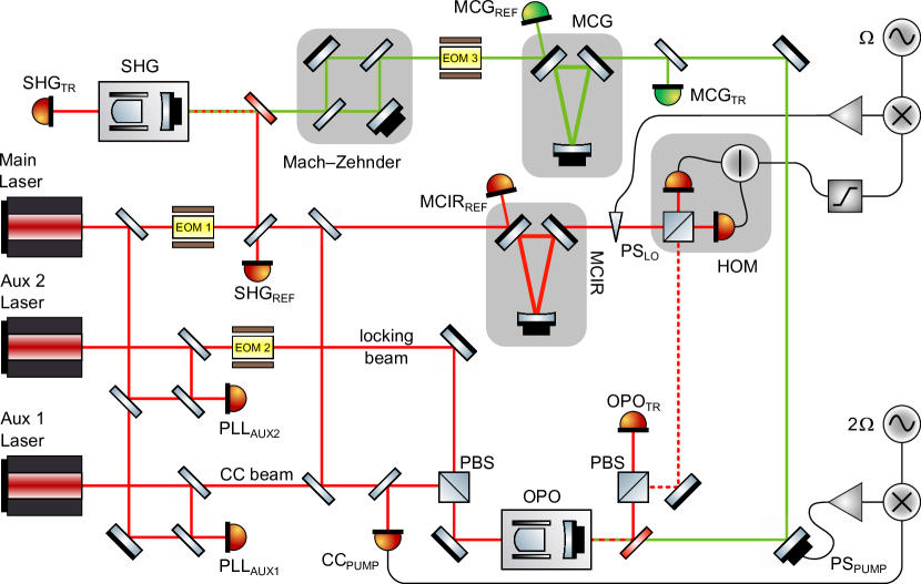
The experimental setup (Fig.1) is a FrequencyIndependent Squeezing (FIS) source at the interferometer carrier wavelength i.e , inspired by a similar system developed at GEO600 [9]. In this setup, squeezed states of light are produced with an OPO pumped with a second harmonic beam, depicted in green in Fig.1. The pump beam is generated from a Main Laser in a Second-Harmonic Generation (SHG) cavity and it is intensity-stabilized by a Mach–Zehnder (MZ) interferometer. The generated squeezed states of light are measured on a Homodyne detector (HOM) using a strong coherent Local Oscillator (LO) beam. Higher order spatial modes of the pump and LO beams are filtered using triangular cavities, Green Modecleaner (MCG) and Infrared Modecleaner (MCIR), respectively. Two auxiliary lasers (Aux 1, Aux 2) are used to lock the OPO cavity and to implement a Coherent Control (CC) of the squeezing angle [10].
2.2 Controls requirements
This complex optical setup requires dedicated control electronics, with the advantage of a high flexibility given by software-driven hardware. For proper operation, auxiliary lasers are locked to the Main laser using two Optical Phase-Locked Loops.
Furthermore we stabilize actively the temperature of the OPO and the SHG crystals with a dedicated digital hardware control loops since the phase-matching in nonlinear crystals, used in such cavities, occurs only at given temperature. Finally, we control the length of four optical resonators (SHG, OPO, MCIR, MCG), the power of the pump beam, the phase of the generated squeezed state, and the phase of the LO at HOM. Thus, multiple control-loops should be designed to lock all loops in sequence in the shortest possible time for a high duty-cycle of operation. The system must provide the possibility of a parallel work on different parts of the experiment simultaneously. Furthermore a high degree of compatibility with the Virgo software environment is desirable, in view of potential future integration.
2.3 Controls design
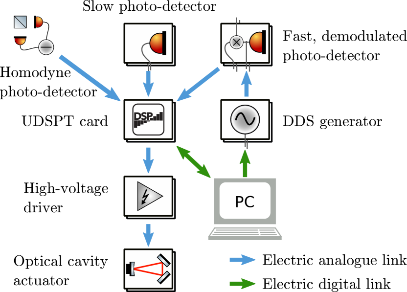
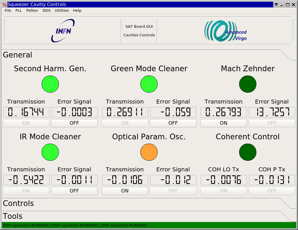
In our solution, OPLLs and temperature controls are locked by independent and sufficiently stable devices, so that additional automation is not required for these elements. On the other hand, the length of the four optical cavities (SHG, OPO, MCIR, MCG), the power of the green beam and both CCs loops are managed by the Digital Signal Processing unit (UDSPT). The length control is implemented using Pound–Drever–Hall technique (PDH technique) [11], while the MZ cavity, and both CC loops are stabilized by a Proportional–Integral–Derivative (PID) controller. The structure of the connections to a UDSPT hardware is shown in Fig. 3. UDSPTs implements lock logic, calculates the feedback correction signals and drives piezo-electric actuators. Tunable Direct Digital Synthesis (DDS) generators provide necessary modulation and demodulation signals where needed. A dedicated GUI (Fig 3) is designed to configure devices remotely. In the next paragraph, we describe the hardware which computes control algorithms.
2.4 Hardware
The core component of the system are the UDSPT cards [18]. They were developed for the real time control of the Virgo super attenuator suspension system. Each card has six Analog-to-Digital Converters and six Digital-to-Analog Converters sampled at a maximum frequency of . The software of each card, developed in the damping-adv Software Development Kit (SDK), is executed in the time between sampling. An integrated Digital Signal Processing (DSP) unit implements efficient, high-order digital loop filters. UDSPT cards also provide advanced connectivity between themselves, with the Virgo time distribution network and Data AcQuisition (DAQ) system [15]. Here, we report the newest feature of the SDK which implements the Finite-State Machine (FSM) engine. We use FSMs for a quick lock acquisition of feedback loops. In order to manage locking loops, we use three cards: squeeze1, squeeze2 and squeeze3. squeeze1 distributes timing and exchanges information with DAQ, squeeze2 manages devices related to the green light path and squeeze3 takes care of MCIR, OPO and CC. The algorithm is described in Section 3.
3 Software description
The presented software is composed of two parts: a Python-based Graphical User Interface (GUI), called sqzGUI, and a software executed by the UDSPTs, called DSPcode–Squeezing. The two pieces communicate via Tango Controls server [17], allowing the simultaneous run of many instances of sqzGUI. Each instance has an equal priority and enables a synchronous co-working. The GUI appearance is shown in Fig. 3. The sqzGUI integrates the control of every device involved in the experiment. The main loop is executed in one second interval. It implements the slow part of the management logic assigned to the UDSPTs, driving namely: MCIR, OPO, SHG, MCG, MZ, the pump beam coherent control (CCpump) and the local oscillator coherent control (CClo) loops.
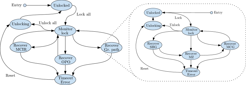
Communication of sqzGUI with each FSMs in the DSPcode occurs via a couple of unidirectional variables: BUTTON and STATUS. The functions for the communication are gathered in the DSP_sq module. The structure of the slow automation logic is split in two and shown in Fig. 4. FSM supervising the green light path is nested in the main FSM and it supervises the lock of the three devices in series conditioning green light.
The sqzGUI python code is self-documented according to PEP 257. Since damping-adv does not support self documentation we focus on the UDSPT code in more details. Nevertheless, comments are included in the code in the most important sections. Each optical cavity, the MZ interferometer and the CC loops are managed by a dedicated FSM implemented in the UDSPTs. The structure of this FSM is shown in Fig. 5.
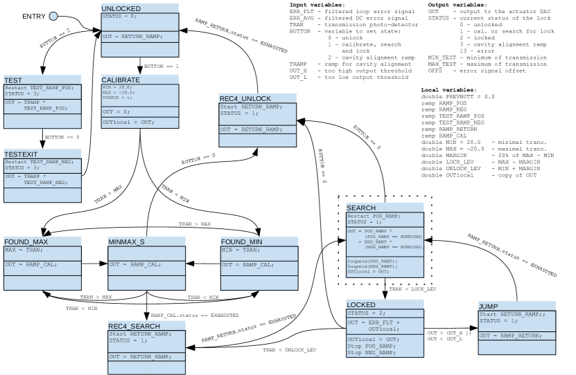
In this graph, the SEARCH state is needed only in case of a resonant cavity lock, hence it is circled with a dashed line. In case of a PID lock, the SEARCH state does not exist and transitions are straightforward. In the figure, the state of the machine is represented as a rectangle divided in three sections with a name of the state above. The first section contains the instructions performed at entry to the state, the middle section encloses the instructions executed every time the FSM algorithm is calculated and the machine is in this state, the last section describes the actions taken when leaving the state. Transitions between states are depicted with arrows, accompanied by the condition of the transition written near the arrow. The FSM can exchange signals with the outer world via one-directional variables declared as input or output. Instead, local variables are exclusive for a particular instance of the machine and their value is preserved between states. A particular type of a variable is ramp which simplifies the generation of ramps. ramp is an object which stores the current value of the ramp, the status of the ramp and it implements three methods: Start, Stop and Restart. The FSM algorithm is executed in the time between consecutive samples of the ADC. Thus, its complexity may limit the maximal sampling frequency. In our case, the ADCs sample at .
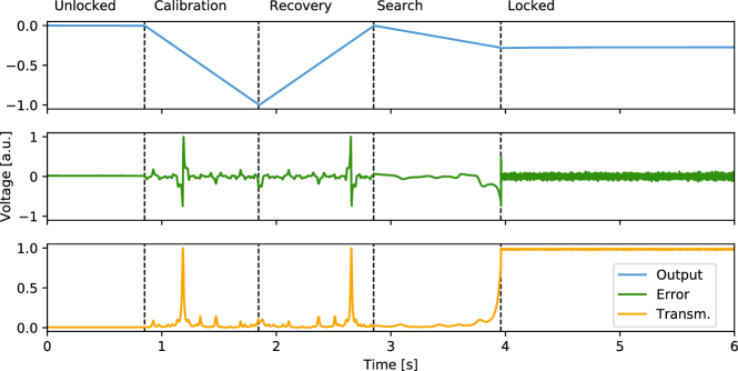
Now, we look at the logic of the lock. At the beginning of the algorithm, the FSM starts in an UNLOCKED state. It is an idle state where the output is zero. Some transitions occur only if the BUTTON value changes. From the UNLOCKED state, one of the two different paths is enabled; the generation of a ramp at the output for a cavity alignment (TEST) or an attempt of lock. In the former case, we set the BUTTON value to “2”. The output is currently a product of the internal ramp generator and the ramp slope TEST_RAMP_POS going from 0 to 1, assuring smooth rise of the signal at the piezo-actuator. At the end of the alignment, we set BUTTON to “0” and the output fades out as TEST_RAMP_NEG varies from 1 to 0. The transition to locking is only possible from UNLOCKED. Setting BUTTON to “1”, the machine goes first through a calibration process. To recognize the proper locking threshold, indicated by the cavity transmission, the machine scans the output and commutes between MINMAX_S, FOUND_MAX and FOUND_MIN registering the highest and the lowest level of transmission. After the calibration, we assume that of the minimum and maximum are the right levels for unlock and lock detection correspondingly. In REC4_SEARCH, the output of the machine turns back to zero to enable SEARCH. The machine remains in the SEARCH state, generating a ramp signal at the output until the locking level is not reached. Search can be interrupted by a manual command. When the LOCKED state is reached, the machine substitutes the ramp at the output with the digitally filtered input signal. The input signal is provided from the demodulated output of the fast photo-detector. There are three possible exits from the LOCKED state: a manual interruption to UNLOCKED, a lock loss when the transmission drops below the unlock level to SEARCH and a technical detail of the implementation when the loop purposely unlocks and moves the output back to the center of the dynamics of the piezo driver via JUMP state. To re-lock after the jump, the machine passes through SEARCH. An example of locking sequence is shown in Fig. 6.
For the visualisation of digitized signals in the experiment, we use dataDisplay software [16]. This tool is developed for the Virgo experiment. It intends to process and visualize the online data with low latency, to facilitate the commissioning and the analysis of the Virgo interferometer.
4 Conclusions
We presented the first application of the new feature of damping-adv SDK. The software significantly speeds up the work on the optical bench thanks to its multi-user architecture, automation and remote access. The complete optical bench for squeezed states of light generation has been automatized and it is ready for future research and development of improved squeezing techniques for gravitational-wave detectors. Thanks to the software-based approach, the existing control system can be easily scaled for large size optical experiments such as, for the alternative use of the squeezed states in gravitational-wave detectors [19, 7, 8].
References
- [1] McKenzie, K., et al. Squeezing in the Audio Gravitational-Wave Detection Band. Phys. Rev. Lett. 93.16 (2004): 161105. doi:10.1103/PhysRevLett.93.161105
- [2] Vahlbruch, H., et al. Coherent Control of Vacuum Squeezing in the Gravitational-Wave Detection Band. Phys. Rev. Lett. 97.1 (2006): 011101. doi:10.1103/PhysRevLett.97.011101
- [3] Vahlbruch, H., et al. Observation of squeezed light with 10-dB quantum-noise reduction. Phys. Rev. Lett. 100.3 (2008): 033602. doi:10.1103/PhysRevLett.100.033602
- [4] Abadie, J., et al. A gravitational wave observatory operating beyond the quantum shot-noise limit. Nat. Phys. 7.12 (2011): 962. doi:10.1038/nphys2083
- [5] Acernese, F., et al. Increasing the astrophysical reach of the Advanced Virgo detector via the application of squeezed vacuum states of light. Phys. Rev. Lett. 123.23 (2019): 231108. doi:10.1103/PhysRevLett.123.231108
- [6] Tse, M., et al. Quantum-enhanced advanced LIGO detectors in the era of gravitational-wave astronomy. Phys. Rev. Lett. 123.23 (2019): 231107. doi:10.1103/PhysRevLett.123.231107
- [7] Sequino, V., et al. EPR experiment for a broadband quantum noise reduction in gravitational wave detectors. GRASS 2019 conference proceeding. doi:/10.5281/zenodo.3554320
- [8] Di Pace, S., et al. Small scale Suspended Interferometer for Ponderomotive Squeezing (SIPS) as test bench for EPR squeezer integration in Advanced Virgo. GRASS 2019 conference proceeding. doi:10.5281/zenodo.3569196
- [9] Khalaidovski, A, et al. Long-term stable squeezed vacuum state of light for gravitational wave detectors. IOP Publ. 29.7 (2012): 075001. doi:10.1088/0264-9381/29/7/075001
- [10] Chelkowski, S., et al. Coherent control of broadband vacuum squeezing. Phys. Rev. A 75.4 (2007): 043814. doi:10.1103/PhysRevA.75.043814
- [11] Black, E. An introduction to Pound–Drever–Hall laser frequency stabilization. Am. J. Phys. 69.1 (2001): 79–87. doi:10.1119/1.1286663
- [12] Gennai, A., et al. A new high performance suspension control system for Advanced Virgo. Virgo note VIR-0374A-15 (2015) available online https://tds.virgo-gw.eu/
- [13] Gennai, A. UDSPT Board Output Noise. Virgo note VIR-0541A-16 (2016) available online https://tds.virgo-gw.eu/
- [14] Bitossi, M., et al. A/D and D/A Processing Unit for Real Time Control of Suspended Masses in Advanced Virgo Interferometer (2019) available online https://tds.virgo-gw.eu/ql/?c=14806
- [15] Acernese, F., et al. Data Acquisition System of the Virgo Gravitational Waves Interferometric Detector. IEEE T. Nucl. Sci. 55.1 (2008): 225-232. doi:10.1109/tns.2007.913937
- [16] LAPP Virgo group Virgo dataDisplay documentation (2019) available online http://lappweb.in2p3.fr/virgo/dataDisplay/
- [17] Tango Community, Tango Controls documentation (2019) available online https://tango-controls.readthedocs.io/en/latest/
- [18] Acernese, F., et al. Advanced Virgo: a second-generation interferometric gravitational wave detector. IOP Publ. 32.2 (2014): 024001. doi:10.1088/0264-9381/32/2/024001
- [19] Ma, Y., et al. Proposal for gravitational-wave detection beyond the standard quantum limit through EPR entanglement. Nat. Phys. 13.8 (2017): 776-780. doi:10.1038/nphys4118
- RF
- Radio Frequency
- AF
- Audio Frequency
- PC
- Personal Computer
- FSM
- Finite-State Machine
- GUI
- Graphical User Interface
- PLL
- Phase-Locked Loop
- OPLL
- Optical Phase-Locked Loop
- DSP
- Digital Signal Processing
- DDS
- Direct Digital Synthesis
- PDH technique
- Pound–Drever–Hall technique
- TEC
- Thermoelectric Cooler
- PID
- Proportional–Integral–Derivative
- IT
- Information Technology
- QoS
- Quality of Service
- VCO
- Voltage-Controlled Oscillator
- DAQ
- Data AcQuisition
- CMRR
- Common-Mode Rejection Ratio
- SDK
- Software Development Kit
- ADC
- Analog-to-Digital Converter
- DAC
- Digital-to-Analog Converter
- RBW
- Resolution Bandwidth
- DC
- Direct Current
- AC
- Alternating Current
- CCpump
- pump beam coherent control
- CClo
- local oscillator coherent control
- EOM
- Electro-Optic Modulator
- UDSPT
- Digital Signal Processing unit
- HV
- High Voltage
- IR
- Infra Red
- HR
- High Reflectivity
- QN
- Quantum Noise
- GW
- Gravitational Wave
- SN
- Shot Noise
- RPN
- Radiation Pressure Noise
- SQL
- Standard Quantum Limit
- BAB
- Bright Alignment Beam
- LO
- Local Oscillator
- CC
- Coherent Control
- FSR
- Free Spectral Range
- FWHM
- Full Width at Half Maximum
- OPO
- Optical Parametric Oscillator
- OPA
- Optical Parametric Amplification
- SHG
- Second-Harmonic Generation
- MCIR
- Infrared Modecleaner
- MCG
- Green Modecleaner
- MZ
- Mach–Zehnder
- PPKTP
- Periodically Poled Potassium Titanyl Phosphate
- RoC
- Radius of Curvature
- TEM
- Transverse-Electo-Magnetic
- CCB
- Coherent Control Beam
- HOM
- Homodyne detector
- FIS
- FrequencyIndependent Squeezing