Anisotropy-induced Extrinsic Chirality and Chiral Discrimination of Surface Plasmon Polaritons
Abstract
We present the characteristics of a simple waveguiding structure constructed by anisotropic birefringent crystal-metal-chiral medium, anisotropic-metal-chiral in short, and reveal the chiral-dependent dispersion and propagation properties of the surface plasmon polaritons (SPPs). We demonstrate its remarkable discrimination ability to the magnitude and sign of both the real and imaginary part of the chirality parameter. The anisotropy plays a key role in such performance and shows tuneable ability in enantiomeric discrimination even when the chirality parameter is complex-valued. Most importantly, the physical origin of chiral discrimination stems from the extrinsic chirality of the system, which arises from the mutual orientation of the SPPs and the optical axis. Moreover, we also clarify the fundamental physics behind the chiral discriminating behaviour by associating the intrinsic quantum spin Hall effect (QSHE) of the SPPs with the electromagnetic field analysis. This structure does not rely on complicated fabrication but provides the opportunity of on-chip surface-sensitive biosensing. We anticipate that our work will stimulate intensive research to investigate the anisotropy-induced chiral sensing techniques in plasmonic platforms.
Chirality refers to the symmetry property of an object that is not congruent with its mirror image. Manifestations of chirality exist ubiquitously in nature from the DNA molecule to human hands and maelstrom in the ocean and spiral galaxy in the universe. In optics, chiral medium exhibits optical activity, also known as circular birefringence (CB), which describes the ability to rotate the polarization state of light and circular dichroism (CD), which measures the differential transmission of circularly polarized waves. Based on these effects, many optical schemes have been proposed for chiral sensing and discrimination, that is a terminology for the method to differentiate chiral enantiomers (the chiral object and its mirror image). Chiral discrimination is especially important for pharmaceutical applications as nearly 50 of the drugs are chiral and among which most of their chiral enantiomeric couterparts are toxicMane (2016); Nguyen et al. (2006). However, discrimination of chiral objects via optical measurements by CB and CD are generally challenging because the chiral-dependent signals are inherently weak. Engineering complex structures Liu et al. (2009); Ren et al. (2012); Cui et al. (2014); Hentschel et al. (2017); Lodahl et al. (2017); Mohammadi et al. (2018), such as plasmonic metamaterials, would amplify the detected signals but it heavily relies on sophisticated complex nanofabrication procedures.
Here we propose an anisotropic-metal-chiral waveguiding structure and address its ability to unambiguously detect both the real and imaginary part of the chirality parameter . The introduction of a structure with a plethora of novel materials has been reported as enhancing its optical performance. We consider anisotropic crystal as a good candidate because it is convincing that anisotropy would provide the conventional waveguides with brand new properties, as many works have discovered novel phenomena such as a new class of hybridized SPPsMarcuse and Kaminow (1979); Knoesen et al. (1988); Krokhin et al. (2007); Nagaraj and Krokhin (2010); Liscidini and Sipe (2010); Li et al. (2008); Wang et al. (2011); Zhou et al. (2015); Warmbier et al. (2012); Luo et al. (2013); Li et al. (2013); Zhou et al. (2019) and tunable photonic bound states in the continuum (BICs)Gomis-Bresco et al. (2017); Mukherjee et al. (2018); Horsley (2019); Mukherjee et al. (2019) in waveguiding structures that contain anisotropic crystals. Meanwhile, the introduction of chirality to convention plasmonic waveguides also leads to interesting physics such as enhancement of SPPs propagation and hybridized SPPsMi and Van (2014); Zhang and Li (2016); Zhang et al. (2017). However, in these works, enantiomeric chirality parameters that contain a pair of opposite handedness would result in the same effect to the system and thereby failing in chiral discrimination. A recent work shows that sub-millidegree angle-resolved chiral surface plasmon resonance (CHISPR) scheme can detect the absolute chirality (handedness and magnitude)Droulias and Bougas (2019), which provides another proof that chiral plasmonics has prominent application in chiral sensing. It would be interesting and inspiring to investigate the problem of what will happen if both the anisotropy and the chirality are involved in a plasmonic waveguide?
We theoretically answer this question by demonstrating that the proposed anisotropic-metal-chiral structure enables the detection of the magnitude and sign of both the real and imaginary part of the chirality parameter . And for the first time the dispersion relation equation and the corresponding physical pictures are presented in such a system. We show the fundamental characteristics of the SPPs in the structure including the theoretical derivation and analysis of the anisotropic-chiral SPPs. Most importantly we discuss the fundamental physics behind our findings.
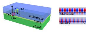
We restrict ourselves to the simplest waveguiding structure fabricated with uniaxially anisotropic crystal, metal and chiral medium; the optical axis (OA) of the crystal is set to lie in the or plane that forms an angle or with respect to the wave propagation direction , respectively, as shown in Fig. 1. The more complicated case when the OA has projections in both or plane is not the focus of this work for simplicity as it is intuitively a problem of the summation of the two separate cases above. We also would not consider the excitation of SPPs for the same reason.
In a chiral medium: , , where , and are the chirality strength, the permittivity and permeability of the chiral material, respectively. are two eigen-wavenumbers corresponding to the right-handed circularly polarized (RCP) wave and left-handed circularly polarized (LCP) wave, respectively. In the bulk material, Maxwell’s equations have a general form . For the anisotropic medium, we only consider when the optical axis lies in the planeWang et al. (2011)(when it lies in the plane, no coupling of SPPs from two interfaces exist, see Supplemental Material),
| (1) |
with , where is the propagation constant and is the decay constant of the SPPs, and , (), representing the relative permittivity for the extraodinary and ordinary wave, respectively. After some deduction procedure (see Supplemental Material), we get two independent decay constants for the ordinary wave and extraordinary wave in the anisotropic medium and , respectively. Applying boundary conditions yields the dispersion relation for the SPPs:
| (2) |
where is the wave impedance of the chiral medium, the permittivity of the metal, the SPPs decay constants in the metal (Drude model, in this work we use gold and the parameters can be found in Ref.Zhang and Li (2016)) and the decay constants in the chiral medium for RCP and LCP with .
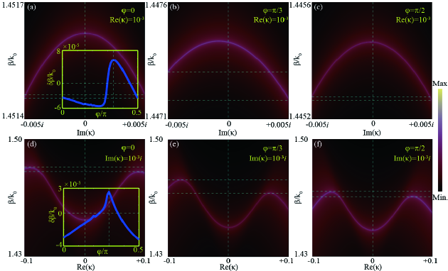
We stress here that the choice of material parameters such as the permittivity would not affect the main conclusions we get in this paper. Throughout this paper we set nm, , , and a representative wavelength at nm for its broad applications in optics and communications. The dispersion diagrams for various central film thickness and the discussion on material parameters are shown in the Supplemental Material. In Fig. 2 we show the dependence of the propagation constant () at nm on the real and imaginary part of the chirality parameter , with different optical axis angles () taken into consideration. The diagrams are drawn by the density plot of the inverse determinant of the boundary condition matrix (Equation (2)) of the system. This is a standard method to obtain a plot whose maxima correspond to the dispersion branchesGangaraj and Monticone (2019). Our discussion with respect to is restricted in the range of 0 to for simplicity since the result would be reversed for considering the mirror symmetry.
To avoid violating the passivity, we ensure that Im(), so Im() should be smaller than 0.007. In Fig. 2a, b and c, we vary Im() between -0.005 and +0.005 and fix Re() at , where we can see that high symmetry is maintained with subtle difference for at Im() as we scan Im() when and . While an apparent differential is observed for Im() when . Meanwhile, in Fig. 2d, e and f, we vary Re() between -0.1 and +0.1 to better illustrate the differtial propagation constant and fix Im() at where an obvious increase of difference is also obtained for , see Fig. 2e. More discussions of multiple combinations of Re() and Im() can be found in the Supplemental Material.
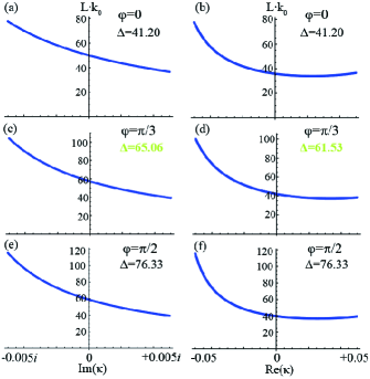
In fact, can not be measeured directly, what measurable is the propagation length (Im) detected by near-field imagingMarquart et al. (2005); Jahng et al. (2015). Fig. 3 shows the propagation length as functions of the real and imaginary part of . To clarify the relationship between and , we calculate instead of , where we choose nm in our calculation. We scan among and investigate the dependence of on its magnitude and sign. We also study the enantiomeric discrimination of the complex-valued chirality of the system. Intriguingly, when , as the illustrations with respect to in Fig. 3c and Fig. 3d obviously demonstrate that and . This indicates a differential propagation length of 880 nm occurs for and . Therefore, when the optical axis has an orientation , the anisotropic-chiral SPPs can discriminate chiral enantiomers even when the chirality parameter is complex valued as the propagation length of the SPPs are different for . However, such a behavior vanishes as implied by the same in Fig. 3a, b and c, d when and .
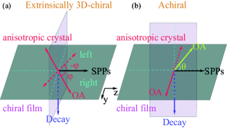
Such a simple structure offers us the opportunity of on-chip bio-sensing with easy fabrication and surface detection. We argue that the chiral sensing ability of the proposed structure originates from the extrinsic 3D-chirality of the system, which highly resembles the extrinsic 3D-chirality in 2D metamaterialsPlum et al. (2009); Plum (2016). Here, chirality is drawn extrinsically from the mutual orientation of the SPP decay direction pointing to the chiral medium, the SPP propagation direction and the optical axis as schematically illustrated by Fig. 4.
In Fig. 4a, when the optical axis lies in the waveguide plane and forms an azimuth angle with respect to the SPP propagation direction, the extrinsic 3D-chirality is readily seen by considering the experimental arrangement of the three colored solid arrows. Since the SPP direction is fixed along and we focus on the SPPs that close to the chiral medium which constantly decay towards the chiral medium, the system is mirror asymmetric and the chirality of is solely determined by the orientation of the optical axis, namely right-handed when and left-handed when (equivalent to ). In particular, as shown in Fig. 4b: 1) when that is the OA superimposes on the SPP propagation, the system loses chirality; 2) when that is the OA lies orthoganal to the SPP propagation, the system lacks chirality because of failure to determine the system’s handedness as OA lies in and means the same thing; 3) when the optical axis lies perpendicular to the waveguide plane and forms an inclination angle with respect to the SPP propagation direction, the three colored arrows will be co-planar thereby losing chirality. These facts essentially explain the origin of the chiral sensing effect and why when the OA lies at and the system can not discriminate chiral enantiomers.
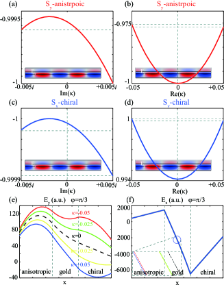
It has been shown that the transverse spin angular momentum (SAM) carried by SPPs is a manifestation of the intrinsic quantum spin Hall effect (QSHE) of lightBliokh et al. (2015); Aiello et al. (2009); Bliokh and Nori (2012, 2015); Bliokh et al. (2014); Alizadeh and Reinhard (2015); Zhao et al. (2016). On the basis of this fundamental effect, we study numerically the impact of anisotropy and chirality on distribution of the transverse SAM and electric field in the system. Fig. 5 describes the chiral-dependent transverse SAM when , where Neugebauer et al. (2015); Kalhor et al. (2016). For simplicity we set to be pure imaginary-valued and real-valued. It is clear that the unequivalent transverse SAM at Im() exist (but not exist when and , see Suppplmental Material). The opposite signs of transverse SAM distribution in the two media are due to spin-locking propertyKalhor et al. (2016) of SPPs. This proves the validity of our anlytical results previously shown. Fig. 3e reveals a distinct behavior contrary to isotropic systems that the transverse component emerges even when if . The introduction of anisotropy leads to asymmetric distribution for Im() and Re() and thereby forming a substantial change of TM to TE conversion that results in the differential propagation length . Interestingly, Fig. 3f presents that the longitudinal electric field component depends neglegibly on the sign and magnitude of since the cuves overlap with each other. Therefore, it is not the change of refractive index due to the orientation of optical axis nor the magnitude change of chirality that causes the chiral discrimination. Notably, the existence of hybridized SPPs due to anisotropy is the fundamental reason for the discrimination of the chirality.
It is necessary to stress here that essentially is a quantity that can be measured indirectly. A particle in the surface plasmonic field experiences an anomalous lateral optical force perpendicular to the direction of the momentum of the SPPsBliokh et al. (2014); Wang and Chan (2014); Kalhor et al. (2016). Such lateral force is proportional to the transverse SAM thus it can be harnessed for manipulation of small particles which in turn can be regarded as a feedback for chiral sensing of the thin (subwavelength) chiral films.
In summary, the proposed simple system allows unambiguous sensing and detection of the magnitude and handedness of both the real and imaginary part of the chirality parameter . This phenomenon is due to the extrinsic chirality, which arises from the mutual orientation of the SPPs and the optical axis. Specifically, when the optical axis lies at azimuth angle or , the SPPs can detect the magnitude and sign of both the real and imaginary part of the chirality parameter but can not discriminate chiral enantiomers; when , however, the SPPs can detect the magnitude and sign of both the real and imaginary part of the chirality parameter as well as discriminate chiral enantiomers even when is complex-valued. The chiral sensitivity of the proposed system can be realized by rotating the waveguide so that the optical axis orientation determines the measurement of chiral-dependent differential propagation length of the SPPs. Such a simple waveguiding structure offers an theoretical instruction to chiral plasmonic device design and can be of great interest in chiral-biosensing applications.
Acknowledgements
This work was supported by the National Natural Science Foundation of China (NSFC) under grant number 60977032 and the Program for Innovation Research of Science of Harbin Institute of Technology (PIRS-HIT), China (Grant No. T201407).
References
- Mane (2016) Sachin Mane, “Racemic drug resolution: a comprehensive guide,” Anal. Methods 8, 7567–7586 (2016).
- Nguyen et al. (2006) Lien Ai Nguyen, Hua He, and Chuong Pham-Huy, “Chiral drugs: An overview,” Int. J. Biomed. Sci. 2, 85–100 (2006).
- Liu et al. (2009) N. Liu, H. Liu, S. Zhu, and H. Giessen, “Stereometamaterials,” Nature Photon. 3, 157 (2009).
- Ren et al. (2012) M. Ren, E. Plum, J. Xu, and N. I. Zheludev, “Giant nonlinear optical activity in a plasmonic metamaterial,” Nature Commun. 3, 833 (2012).
- Cui et al. (2014) Y. Cui, L. Kang, S. Lan, S. Rodrigues, and W. Cai, “Giant chiral optical response from a twisted-arc metamaterial,” Nano Lett. 14, 1021 (2014).
- Hentschel et al. (2017) Mario Hentschel, Martin Schäferling, Xiaoyang Duan, Harald Giessen, and Na Liu, “Chiral plasmonics,” Sci. Adv. 3, e1602735 (2017).
- Lodahl et al. (2017) Peter Lodahl, Sahand Mahmoodian, Søren Stobbe, Arno Rauschenbeutel, Philipp Schneeweiss, Jürgen Volz, Hannes Pichler, and Peter Zoller, “Chiral quantum optics,” Nature 541, 473–480 (2017).
- Mohammadi et al. (2018) E. Mohammadi, K. L. Tsakmakidis, A. N. Askarpour, P. Dehkhoda, A. Tavakoli, and H. Altug, “Nanophotonic platforms for enhanced chiral sensing,” ACS Photonics 5, 2669–2675 (2018).
- Marcuse and Kaminow (1979) D. Marcuse and I. Kaminow, “Modes of a symmetric slab optical waveguide in birefringent media - part ii: Slab with coplanar optical axis,” IEEE J. Quantum Elect. 15, 92–101 (1979).
- Knoesen et al. (1988) A. Knoesen, T. K. Gaylord, and M. G. Moharam, “Hybrid guided modes in uniaxial dielectric planar waveguides,” J. Lightwave Technol. 6, 1083–1104 (1988).
- Krokhin et al. (2007) A. A. Krokhin, A. Neogi, and D. McNeil, “Long-range propagation of surface plasmons in a thin metallic film deposited on an anisotropic photonic crystal,” Phys. Rev. B 75, 235420 (2007).
- Nagaraj and Krokhin (2010) Nagaraj and A. A. Krokhin, “Long-range surface plasmons in dielectric-metal-dielectric structure with highly anisotropic substrates,” Phys. Rev. B 81, 085426 (2010).
- Liscidini and Sipe (2010) Marco Liscidini and J. E. Sipe, “Quasiguided surface plasmon excitations in anisotropic materials,” Phys. Rev. B 81, 115335 (2010).
- Li et al. (2008) Rui Li, Chen Cheng, Fang-Fang Ren, Jing Chen, Ya-Xian Fan, Jianping Ding, and Hui-Tian Wang, “Hybridized surface plasmon polaritons at an interface between a metal and a uniaxial crystal,” Appl. Phys. Lett. 92, 141115 (2008).
- Wang et al. (2011) Xiaolei Wang, Pei Wang, Junxue Chen, Yonghua Lu, Hai Ming, and Qiwen Zhan, “Theoretical and experimental studies of surface plasmons excited at metal-uniaxial dielectric interface,” Appl. Phys. Lett. 98, 021113 (2011).
- Zhou et al. (2015) Hongli Zhou, Xueru Zhang, Degui Kong, Yuxiao Wang, and Yinglin Song, “Complete dispersion relations of surface plasmon polaritons at a metal and birefringent dielectric interface,” Appl. Phys. Exp. 8, 062003 (2015).
- Warmbier et al. (2012) Robert Warmbier, George S. Manyali, and Alexander Quandt, “Surface plasmon polaritons in lossy uniaxial anisotropic materials,” Phys. Rev. B 85, 085442 (2012).
- Luo et al. (2013) Rui Luo, Ying Gu, Xiankuo Li, Luojia Wang, Iam-Choon Khoo, and Qihuang Gong, “Mode recombination and alternation of surface plasmons in anisotropic mediums,” Appl. Phys. Lett. 102, 011117 (2013).
- Li et al. (2013) X. Li, Y. Gu, R. Luo, L. Wang, and Q. Gong, “Effects of dielectric anisotropy on surface plasmon polaritons in three-layer plasmonic nanostructures,” Plasmonics 8, 1043–1049 (2013).
- Zhou et al. (2019) Chenzhang Zhou, Tom G. Mackay, and Akhlesh Lakhtakia, “Surface-plasmon-polariton wave propagation supported by anisotropic materials: Multiple modes and mixed exponential and linear localization characteristics,” Phys. Rev. A 100, 033809 (2019).
- Gomis-Bresco et al. (2017) Jordi Gomis-Bresco, David Artigas, and Lluis Torner, “Anisotropy-induced photonic bound states in the continuum,” Nature Photonics 11, 232–236 (2017).
- Mukherjee et al. (2018) Samyobrata Mukherjee, Jordi Gomis-Bresco, Pilar Pujol-Closa, David Artigas, and Lluis Torner, “Topological properties of bound states in the continuum in geometries with broken anisotropy symmetry,” Phys. Rev. A 98, 063826 (2018).
- Horsley (2019) S. A. R. Horsley, “Indifferent electromagnetic modes: Bound states and topology,” Phys. Rev. A 100, 053819 (2019).
- Mukherjee et al. (2019) Samyobrata Mukherjee, Jordi Gomis-Bresco, Pilar Pujol-Closa, David Artigas, and Lluis Torner, “Angular control of anisotropy-induced bound states in the continuum,” Opt. Lett. 44, 5362–5365 (2019).
- Mi and Van (2014) Guangcan Mi and Vien Van, “Characteristics of surface plasmon polaritons at a chiral–metal interface,” Opt. Lett. 39, 2028–2031 (2014).
- Zhang and Li (2016) Qiang Zhang and Junqing Li, “Characteristics of surface plasmon polaritons in a dielectrically chiral-metal-chiral waveguiding structure,” Opt. Lett. 41, 3241–3244 (2016).
- Zhang et al. (2017) Qiang Zhang, Junqing Li, Xingguang Liu, and Demissie J. Gelmecha, “Dispersion, propagation, and transverse spin of surface plasmon polaritons in a metal-chiral-metal waveguide,” Appl. Phys. Lett. 110, 161114 (2017).
- Droulias and Bougas (2019) Sotiris Droulias and Lykourgos Bougas, “Surface plasmon platform for angle-resolved chiral sensing,” ACS Photonics 6, 1485–1492 (2019).
- Gangaraj and Monticone (2019) S. Ali Hassani Gangaraj and Francesco Monticone, “Do truly unidirectional surface plasmon-polaritons exist?” Optica 6, 1158–1165 (2019).
- Marquart et al. (2005) Carsten Marquart, Sergey I. Bozhevolnyi, and Kristjan Leosson, “Near-field imaging of surface plasmon-polariton guiding in band gap structures at telecom wavelengths,” Opt. Express 13, 3303–3309 (2005).
- Jahng et al. (2015) Junghoon Jahng, Faezeh Tork Ladani, Ryan Muhammad Khan, Xiaowei Li, Eun Seong Lee, and Eric Olaf Potma, “Visualizing surface plasmon polaritons by their gradient force,” Opt. Lett. 40, 5058–5061 (2015).
- Plum et al. (2009) E. Plum, X.-X. Liu, V. A. Fedotov, Y. Chen, D. P. Tsai, and N. I. Zheludev, “Metamaterials: Optical activity without chirality,” Phys. Rev. Lett. 102, 113902 (2009).
- Plum (2016) Eric Plum, “Extrinsic chirality: Tunable optically active reflectors and perfect absorbers,” Appl. Phys. Lett. 108, 241905 (2016).
- Bliokh et al. (2015) Konstantin Y. Bliokh, Daria Smirnova, and Franco Nori, “Quantum spin hall effect of light,” Science 348, 1448–1451 (2015).
- Aiello et al. (2009) Andrea Aiello, Norbert Lindlein, Christoph Marquardt, and Gerd Leuchs, “Transverse angular momentum and geometric spin hall effect of light,” Phys. Rev. Lett. 103, 100401 (2009).
- Bliokh and Nori (2012) Konstantin Y. Bliokh and Franco Nori, “Transverse spin of a surface polariton,” Phys. Rev. A 85, 061801 (2012).
- Bliokh and Nori (2015) Konstantin Y. Bliokh and Franco Nori, “Transverse and longitudinal angular momenta of light,” Phys. Rep. 592, 1 – 38 (2015).
- Bliokh et al. (2014) Konstantin Y. Bliokh, Aleksandr Y. Bekshaev, and Franco Nori, “Extraordinary momentum and spin in evanescent waves,” Nat. Commun. 5, 3300 (2014).
- Alizadeh and Reinhard (2015) M. H. Alizadeh and Björn M. Reinhard, “Transverse chiral optical forces by chiral surface plasmon polaritons,” ACS Photonics 2, 1780–1788 (2015).
- Zhao et al. (2016) Yang Zhao, Amr A. E. Saleh, and Jennifer A. Dionne, “Enantioselective optical trapping of chiral nanoparticles with plasmonic tweezers,” ACS Photonics 3, 304–309 (2016).
- Neugebauer et al. (2015) Martin Neugebauer, Thomas Bauer, Andrea Aiello, and Peter Banzer, “Measuring the transverse spin density of light,” Phys. Rev. Lett. 114, 063901 (2015).
- Kalhor et al. (2016) Farid Kalhor, Thomas Thundat, and Zubin Jacob, “Universal spin-momentum locked optical forces,” Appl. Phys. Lett. 108, 061102 (2016).
- Wang and Chan (2014) S. B Wang and C. T Chan, “Lateral optical force on chiral particles near a surface,” Nat. Commun. 5, 3307 (2014).