The critical role of shell in enhanced fluorescence of metal-dielectric core-shell nanoparticles
Abstract
Large scale simulations are performed by means of the transfer-matrix method to reveal optimal conditions for metal-dielectric core-shell particles to induce the largest fluorescence on their surfaces. With commonly used plasmonic cores (Au and Ag) and dielectric shells (SiO2, Al2O3, ZnO), optimal core and shell radii are determined to reach maximum fluorescence enhancement for each wavelength within – nm (Au core) and – nm (Ag core) bands, in both air and aqueous hosts. The peak value of the maximum achievable fluorescence enhancement factors of core-shell nanoparticles, taken over entire wavelength interval, increases with the shell refractive index and can reach values up to 9 and 70 for Au and Ag cores, within nm and nm wavelength ranges, respectively, which is much larger than that for corresponding homogeneous metal nanoparticles. Replacing air by an aqueous host has a dramatic effect of nearly halving the sizes of optimal core-shell configurations at the peak value of the maximum achievable fluorescence. In the case of Au cores, the fluorescence enhancements for wavelengths within the first near-infrared biological window (NIR-I) between 700 and 900 nm can be improved twofold compared to homogeneous Au particle when the shell refractive index . As a rule of thumb, the wavelength region of optimal fluorescence (maximal nonradiative decay) turns out to be red-shifted (blue-shifted) by as much as nm relative to the localized surface plasmon resonance wavelength of corresponding optimized core-shell particle. Our results provide important design rules and general guidelines for enabling versatile platforms for imaging, light source, and biological applications.
Institute of Electronic Engineering, China Academy of Engineering Physics, Mianyang, 621999, China \altaffiliationContributed equally to this work \altaffiliationContributed equally to this work \alsoaffiliationInstitute of Electronic Engineering, China Academy of Engineering Physics, Mianyang, 621999, China
![[Uncaptioned image]](/html/2003.11850/assets/figs/TOC.jpg)
1 Introduction
Fluorescence-based spectroscopy and imaging techniques have become a promising solution to meet the demands of various emerging applications such as single molecule detection 1, 2, early diagnosis 3, 4, 5, food and drug safety 6. The advantage of fluorescence emitters to label the target species at a molecular level makes it an ideal tool for fingerprint tags 7. Fluorescence spontaneous emission also serves as the foundation of advanced light sources such as micro/nano light emitting diodes (LEDs) for high-resolution displays 8, 9 and single photon sources for quantum photonics 10, 11. Independent spatial and temporal radiation characteristics of fluorescence emitters have been employed in a super-resolution imaging. Despite all those attractive features, intrinsic fluorescence emission is very weak, and challenges the development of high performance devices.
Plasmonic nanostructures hold a great potential in enhancing fluorescence emission 12, 13, 14, 15, 16. On one hand, collective electron oscillations on the surface of plasmonic nanostructure can generate a strong local electric field enhancement to boost the excitation rate of the fluorescence emitter 17, 12, 13, 18, 19. On the other hand, the presence of metal nanostructure in the vicinity of the fluorescence emitter affects the local density of optical states (LDOS), thereby tailoring the radiative and nonradiative decay rates 20, 17, 21, 22, 23, 24, 25, 26, 27. An optimal fluorescence enhancement factor requires a delicate balance of the excitation, radiative and nonradiative decay rates 12, 13, 28, 29. To date, plasmonic structures have been developed to obtain fluorescence enhancement, also termed metal-enhanced fluorescence 30, such as metallic layered structures 31, 32, waveguides 33, ordered structures 34, 35, nanoantennas 36, 37, 38, 39, nanoparticles 12, 13, 40, 41 to name just a few.
Compared to other plasmonic alternatives, core-shell nanoparticles possess unique advantages owing to their mass production capability with low cost chemical synthesis methods 42, 43, 44, 45, 46, 47, 48, 49. With regard to tuning the localized surface plasmon resonance (LSPR) wavelength, metal shell particles are superior to dielectric shell particles. As it can be qualitatively understood already from the quasi-static analysis, 50 in the metal shell case one can tune the dipole LSPR between Re for and Re for , where and are core and shell radii, and , and correspond to dielectric permittivities of a core, shell and host medium, respectively. For Ag and Au shells, this translates into the whole visible and near-infrared range simply by a control of the core-shell morphology, i.e. of the ratio 50, 42, 51, 43. In the dielectric shell case, the tunability limits are set between Re for and Re for , 50 and the resulting tunability is narrower and typically of the order of nm. For the same reason, initial search of fluorescence enhancement focused more on metal shell particles, whereas the use of metal-dielectric core-shell particles, apart of some preliminary work 45, 46, 52, 53, 54, 55, 56, 57, 58, 59, 60, has still remained to be underestimated in the current literature.
In what follows, we show that the neglect of dielectric shell particles has been largely undeserved. We searched for experimentally feasible metal-dielectric core-shell configurations with common Au and Ag cores and widely available dielectric shell materials (SiO2, Al2O3, ZnO) whose refractive indices are higher than that of the host medium (air or water), for optimal fluorescence enhancements. The outcome is that, in spite of relatively narrow tunability of the LSPR wavelength of those particles, there is still enough of design flexibility left for optimally designed nanoparticles to enable (i) comparable or even larger fluorescence enhancement as metal shells 61 and (ii) significantly enhanced fluorescence compared to homogeneous metal particles 45, 46, 59, 58, 60, due to the efficient tailoring of the electric near-field and fluorescence decay rates by dielectric shell. Furthermore, the dielectric shell of a metal-dielectric core-shell nanoparticle (also called shell-isolated nanoparticle 60) provides a convenient way to separate the fluorescence emitter and the metallic component with a predetermined distance, thus avoiding the quenching problem 45, 12, 62, 63, 52, 57. In our simulations, we have employed a rigorous and computationally fast transfer matrix method, which can be viewed as an extension of the theory for homogeneous particles 20, 21, 22, 23 to a multilayered case with an arbitrary number of layers, to obtain the radiative and nonradiative decay rates 24, 25, the electric field distribution 64, and, as a result, the fluorescence enhancement factor.
2 Methods
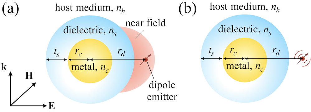
Core-shell nanoparticle enhanced fluorescence can be described in two steps as shown in Figure 1, with the fluorescence emitter being modelled as an oscillating dipole 20, 17, 21, 22, 23, 24. First, the core-shell nanoparticle locally enhances an electric field under a plane wave excitation, thereby amplifying the excitation rate of the fluorescence emitter in its proximity. Second, after being excited, the emitter itself radiates, and mutual interaction with the nanoparticle modifies the radiative and nonradiative decay rates of an emitter 22, 13, 18, 39. Note that the fluorescence excitation and emission processes are treated independently (i.e. weak coupling) and the emitter is assumed to be below saturation 12, 13.
2.1 Excitation process: electric field enhancement
Under a plane wave illumination, the electric field in -th layer of a general multilayered core-shell nanoparticle, from the core () up to the host medium (), where the number of layers in our case is , is expanded into multipole expansion 24:
| (1) |
Here is the composite angular momentum index with and being the usual orbital and magnetic angular momentum numbers, the respective and denote electric (or TM) and magnetic (or TE) polarizations, is the wavenumber in -th shell with refractive index , is the incident wavelength, and are the expansion coefficients, and are vector multipoles 24, 64. The expansion coefficients and can be obtained by matching the tangential components of the electromagnetic fields at each interface by implementing the recursive algorithm.
2.2 Emission process: radiative and nonradiative decay rates
The interaction between the dipole emission and the core-shell nanoparticle can be analytically solved using the transfer matrix method 24, 65. A dipole emitter is assumed to be located at the radial distance , which can be inside the shell or outside the core-shell nanoparticle 45, 46, 62, 47, 49, 53, 55, 56, 54. For non-magnetic core-shell particle and host, the radiative, , and nonradiative decay rates, , normalized with respect to the radiative decay rate in the free space (assumed to have the host permittivity), , can be obtained as 24:
| (2) |
where the respective “” and “” indicate the perpendicular (radial) and parallel (tangential) dipole orientation relative to the particle surface, is the refractive index of the dissipative component with a non-zero imaginary part (i.e. the plasmonic metal core in our case), is the refractive index of the host medium, and are linear combinations of Riccati-Bessel functions, , and , where the subscript corresponds to location of a dipole emitter. The symbols represent volume integrals taken over any absorbing region, i.e. in our case over the entire metal core. Finally, the prime denotes the differentiation with respect to the argument in parentheses.
2.3 Fluorescence enhancement
For light intensities below dye saturation, the fluorescence enhancement factor can be expressed as the product of the excitation rate and the quantum yield, which is essentially related to the electric field distribution and dipole decay rates of the core-shell nanoparticle:
| (3) |
Here the subscript “0” indicates the respective quantity in the free space. The excitation rate can be expressed as , where is the local electric field at the emitter’s position which can be obtained from eq 1, and represents the dipole moment of the emitter. In our simulations we shall use both orientationally averaged electric field intensity and orientationally averaged decay rates. The orientationally averaged electric field intensity is to be understood as the field intensity averaged over a spherical surface of a given fixed radius 64, whereas an orientationally averaged decay rate is determined at a fixed dipole position by averaging over all possible dipole orientations. The surface integrals of intensities can be performed analytically 64, whereas orientation-averaged decay rates can be determined directly from eq 2 as . Fluorescence enhancement at a given radial position will be determined by substituting into eq 3 an average quantum yield
| (4) |
with the intrinsic quantum yield assumed, for simplicity, to be unity. The quantum yield accounts for the competition between the radiative and nonradiative decay rates. Note that .
The above makes it clear that, although the core-shell far-field (i.e. scattering) properties can be, at least qualitatively, understood by the quasi-static analysis 50, 66, the influence of near-fields on fluorescence is much more involved. Below, a systematic investigation is conducted taking into account these near-field effects to find optimal conditions for fluorescence enhancement.
3 Optimized core-shell configurations for fluorescence enhancement
The speed and robustness of our method allows us to perform an optimization study scanning over up to different core-shell configurations for each wavelength and for each shell material. The schematic of the structure is shown in Figure 1 displaying the core-shell nanoparticle with a metal core (with radius and refractive index ) surrounded by a dielectric shell (with thickness and refractive index ). The nanoparticle is embedded in a homogeneous medium with a refractive index , which is set to be air () or water () in what follows. Au and Ag were selected as the core materials. For the sake of comparison with earlier results, Palik et al. 67 data of Au and Ag dielectric function were used in our simulations. Noteworthy, optimally synthesized Au and Ag cores may exhibit lower losses 68, thereby facilitating even higher fluorescence enhancements.
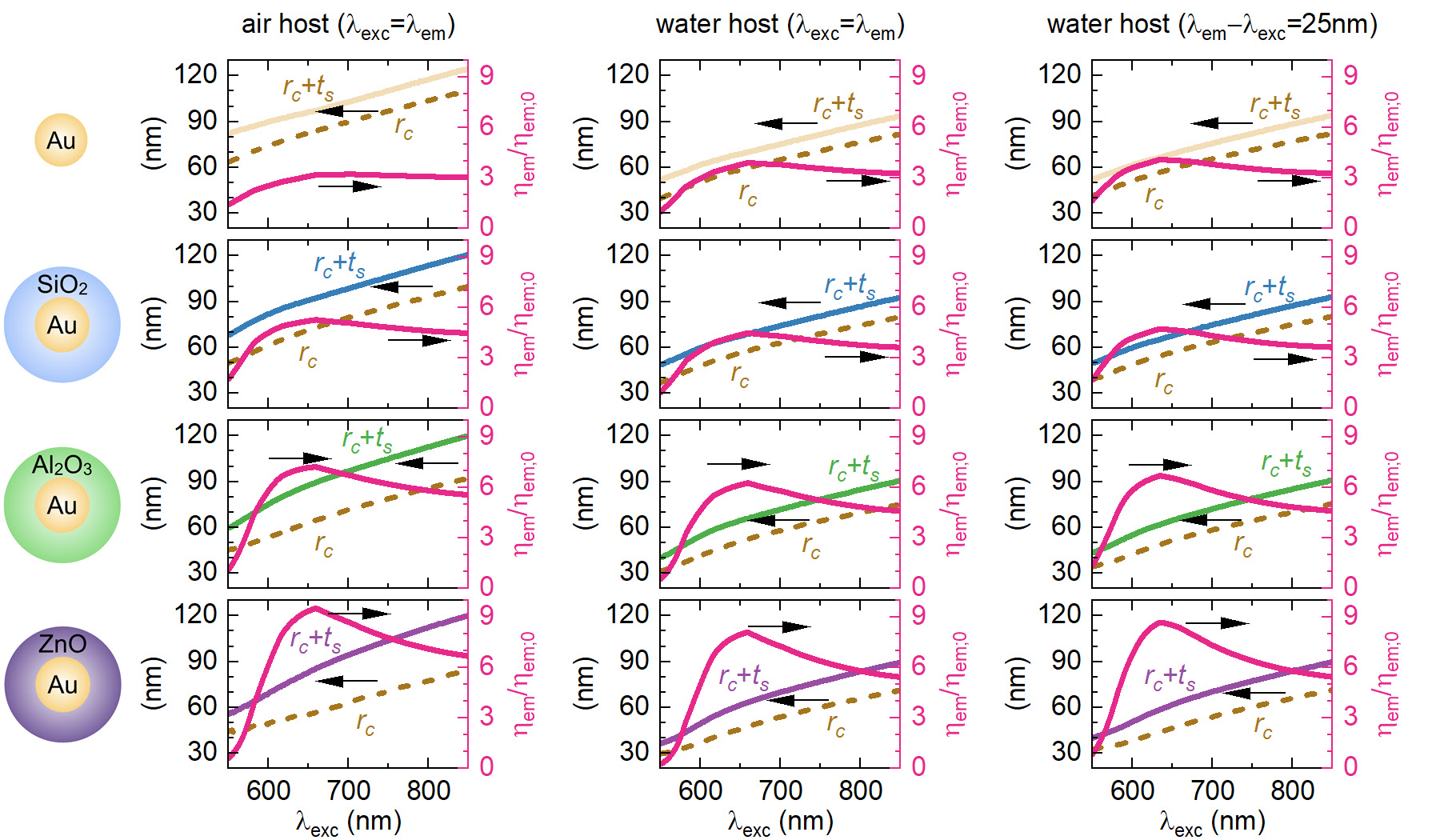
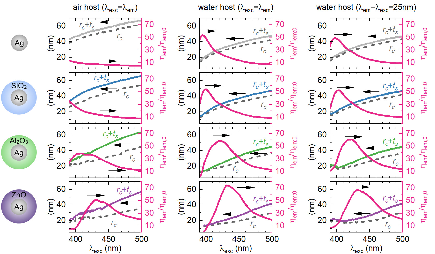
Optimization results are obtained by scanning over different Au (Figure 2) and Ag (Figure 3) core radii within the interval nm and nm, correspondingly. We allow the shell thickness to vary within the interval nm and perform optimization for three different shell refractive indices , , , corresponding to typical values of SiO2, Al2O3, ZnO, all that within nm and nm wavelength ranges for Au and Ag, respectively. The searched intervals for and are justified by the final results shown in Figures 2 and 3 and make use of the fact that too small metal cores cause an increased absorption resulting in relatively enhanced contribution of the nonradiative decay rate which reduces fluorescence. Dyes are assumed to have zero or a moderate Stokes shift of 25 nm, which are the typical values of Alexa fluorophores.
In general, larger fluorescence enhancement factor can be achieved with utilizing shells having higher refractive index. Interestingly, the maximum fluorescence enhancement of Au and Ag core-shell particles covers a large portion of the visible spectrum. For Au cores, the maximum fluorescence enhancement can be achieved between – nm irrespective of the host (air or water), with the fluorescence enhancement overcoming that around homogeneous metal particle within the first near-infrared biological window (NIR-I) between 700–900 nm by a factor of , when the shell refractive index .
Silver has been known for long time as the best surface-enhanced Raman spectroscopy (SERS) 69 and plasmonic material 70, 71. An evidence of this is seen also here in almost an order of magnitude higher maximum fluorescence enhancement () for Ag cores (Figure 3) than in the case of Au cores () (Figure 2), which is a consequence of weaker silver losses. This enables stronger enhancement of the near-field electric field intensities and the resulting excitation rate. Once a proper fluorescence enhancement peak builds up, the ratio of peak fluorescence enhancement values with and without shell is not as high as that for Au cores. However, the difference in the peak values is significantly higher () than for Au cores (). The effect of the Stokes shift on the maximum fluorescence enhancement is clearly visible in both core cases. Given that arbitrary Stokes shifts are, in principle, possible 72, the Stokes shifts could become another useful model parameter.
We conclude this section by an observation, which will be detailed below, that our average fluorescence results shown in Figures 2 and 3 can be easily exceeded by judiciously placing a low- fluorophore () at a hot-spot of the core-shell particle, with the fluorophore dipole moment properly oriented, which can generate a multiplication factor of on top of the results shown in Figures 2, 3.
4 Discussion
An essential prerequisite for our simulations was recently reported efficient determination of orientationally averaged electric field intensities 64, 73, which supplemented earlier efficient calculation of decay rates 24. In essence, surface integrals of electric field intensity can be performed analytically 64 and the calculation of average intensity costs the same computational time as determining intensity at a given point. Below we discuss a number of different aspects related to our optimization results.
4.1 A critical role of the shell
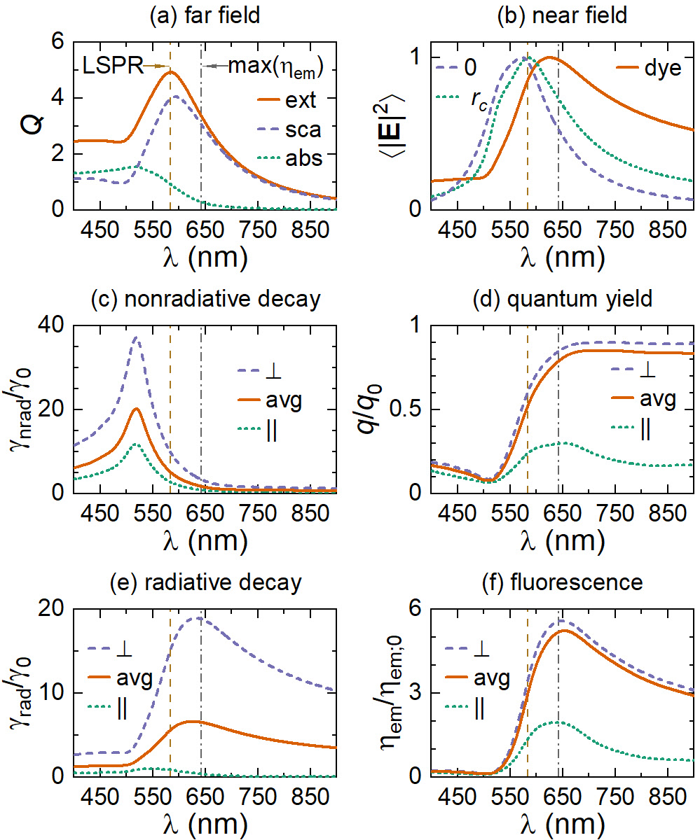
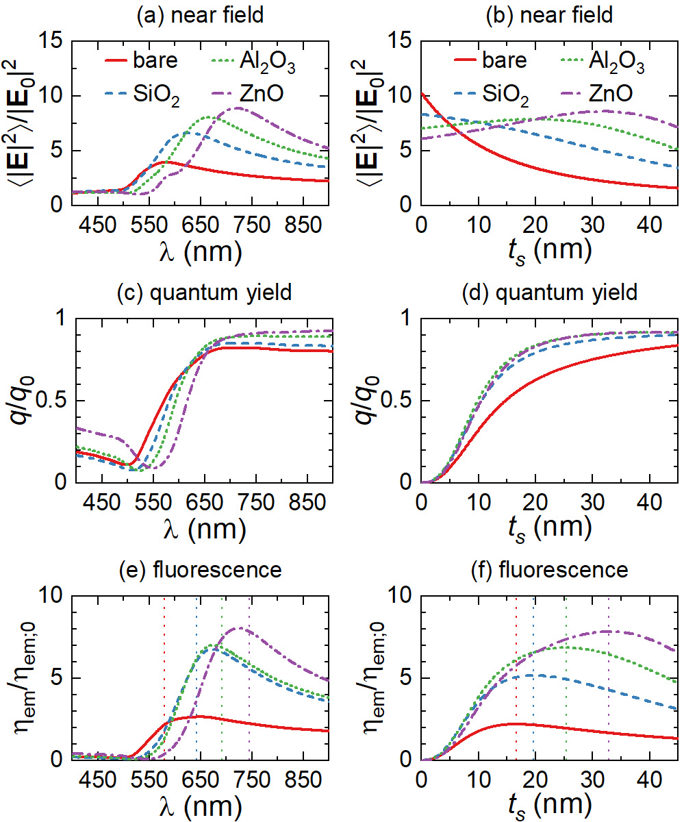
The lesson to be learned from our simulations shown in Figures 2, 3 is obviously that the maximal fluorescence enhancement increases with the shell refractive index. This suggests even higher fluorescence enhancements by using shell materials such as Ta2O5 (), Nb2O5 (), TiO2 (), or Si (). To get more insights about the position of, and the mechanism behind, the maximal fluorescence enhancement, we plot in Figure 4 in details near-field (NF) and far-field properties of Au@SiO2 core-shell with optimal parameters to exhibit maximum achievable fluorescence at nm. An asymmetric Fano-like shape characterizing extinction, scattering and absorption spectra, local electric field enhancement, nonradiative and radiative decay rates, and fluorescence enhancement (Figures 4a-c,e,f) indicates an interference of different multipolar modes 74, 75. As observed by Miroshnichenko 75, the resonant NF enhancement (i.e. local field enhancement that controls the excitation rate, ) can be red-shifted in the Fano case by as much as nm relative to the resonant scattering (i.e. LSPR) for metal-dielectric core-shell particles. The NF red-shift has been known for a long time 76 and its origin can be accounted for by a simple harmonic oscillator model of plasmon oscillations 77. The maximum of radiative decay rate shown in Figure 4e coincides with the maximum of NF at the outer shell surface (Figure 4b), which is seen as the main origin of the red-shift of the maximum of fluorescence enhancement (Figure 4f) relative to the LSPR (Figure 4a). An additional small red-shift of the maximum of fluorescence enhancement (Figure 4f) relative to the maximum of radiative decay rate (Figure 4e) is due to increasing quantum yield (Figure 4d). Note in passing that it has been noted for homogeneous Ag particles that the highest fluorescence enhancement is obtained for an emission wavelength red-shifted from the LSPR 13, yet no explanation has been given.
Of the same magnitude as the red-shift is the blue shift of the maximum of nonradiative decay rate (Figure 4c) relative to the LSPR (Figure 4a). The LSPR position coincides with the maximum of field intensity at the Au core surface (Figure 4b) and the maximum of (Figure 4a). The position of the maximum nonradiative decay rate , which essentially coincides with , is blue-shifted to the LSPR. The difference in the shape of the peaks of and is attributed to a fact that the former describes power loss of a dipole emitter at the shell surface, whereas the latter is the measure of absorption of incident plane arriving from the spatial infinity. The above red and blue shifts relative to the LSPR of corresponding optimized core-shell particle provide important design rules for selected application. Note is passing that there is a number of applications where not only fluorescence enhancement but also an efficient fluorescence quenching is highly desirable 78.
In a Drude-like region above bulk plasma wavelength ( nm for Ag and nm for Au), the loss tangent (i.e. the ratio ) of a noble metal dielectric function decreases with increasing wavelength. Therefore, the use of shells with larger refractive indices, which increases the red shift of their LSPR, and consequently of their NF maximum, creates increasingly favourable conditions for fluorescence enhancement by reducing (increasing) the overall contribution of nonradiative (radiative) decay rates. At the same time, the boundary condition at the shell-host interface for the radial components of electric field, , implies that experiences a jump by the factor of at the host, with being continuous across the shell-host interface. Obviously, the jump in field intensity values at the shell surface becomes more pronounced with larger , enabling to achieve quite large electric field enhancement at the shell-host interface even for relatively thick shells (Figure 5b; Figures S3, S4, see Supporting Information).
Note that the procedure used in Figures 2 and 3 for the search of optimal () configurations implies the fluorescence enhancement to be the largest possible at a given wavelength . This, however, does not restrict the same core-shell to exhibit even larger fluorescence enhancement at another wavelength , which is clearly observed in Figure 5e. Nonetheless, the maxima in Figure 5f, which perfectly correspond to , confirm that () configurations indeed provide optimal at (cf. Figure S2, see Supporting Information).
4.2 Comparison with an experiment
Our optimization results of Sec. 3 provide general guidelines for achieving the highest possible fluorescence enhancements. Before comparing them against an experiment, the following has to be taken into account. First, our simulations assuming either zero Stokes shift, or a model Stokes shift of nm have to be adjusted to the Stokes shift of the fluorophore used. The Stokes shift is strongly dependent on a fluorophore used and can be much larger than the nm 72. Second, optimally fabricated Au and Ag cores may exhibit lower losses 68 than those following from the data of Palik et al 67 used in our simulations, thereby facilitating even higher fluorescence enhancements. Third, optimization results of Sec. 3 assumed orientationally averaged electric field intensity and average dipole orientation. On judiciously placing fluorophore at hot spots of electric field intensity with the fluorophore dipole moment properly oriented such a local fluorescence enhancement can be up to times stronger (Figure S9, see Supporting Information). Last but not the least, simulations of Sec. 3 presumed intrinsic quantum yield . In this regard, any will increase the denominator of eq 4 by . However, for moderate and for the metal-dye separations studied, this contribution is typically negligible compared to other two terms in the denominator (e.g. ). Hence will hardly change the resulting quantum yield of eq 4. However, such a moderate will, according to eq 3, significantly increase the resulting fluorescence enhancement shown in Figures 2, 3 by a factor of . For instance, in the case of low carboxyfluorescein (FAM) and Au@SiO2 core-shell nanoparticles with nm of Ref. 45 [Table 1; Figure 2B] this amounts to the factor of . On the other hand, for cascade yellow (CYe) having an intrinsic quantum efficiency of about and Ag@SiO2 core-shell nanoparticles of Ref. 45 [Table 1; Figure 3] this amounts to the factor of . Therefore, when comparing with experiment, a low- dye () placed at a hot-spot of the core-shell particle can easily generate a multiplication factor of by which the results shown in Figures 2, 3 are to be multiplied. Not surprisingly, initial experiments observed significant fluorescence enhancements especially with low- dyes 45, 46.
4.3 Comparison with metal shells
The highest reported fluorescence enhancements for dielectric () core and Ag shell of comparable sizes tuned to the Fano resonance 61 were in the case of radially oriented dipole located at the hot spot reaching nearly the value of , whereas the enhancements for tangentially oriented dipole hardly exceeded the value of . This results in the dipole orientation averaged fluorescence enhancement of . Our results for dielectric shells presented in Figure 3 show almost four-times larger averaged fluorescence enhancement with much lower shell refractive index () and without the need of keeping the dipole emitter at a hot spot. Here one notable difference between the homogeneous sphere and metal-dielectric core-shell on one hand, and a dielectric-metal core-shell on the other hand, is that in the former case the areas of highest field enhancement are located near the particle poles on the rotation axis parallel to the incident polarization direction, whereas in metallic shells the areas of highest field enhancement are located near the particle poles on the rotation axis perpendicular to the incident polarization 79.
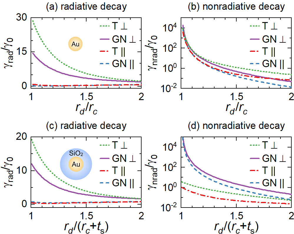
4.4 Quasi-static approximation
The Gersten and Nitzan (GN) quasi-static approximation for determining decay rates 80, which makes use of particle multipolar polarizabilities, , has been known to provide a very good approximation of radiative and nonradiative decay rates in the case of small homogeneous particles 81. A dipolar polarizability with the account of dynamic depolarization and radiative correction 82 (see Sec. 3 in Supporting Information for details) enables rather precise description of the scattering properties of core-shell particles. Nevertheless, the GN approximation 80 largely fails to describe the nonradiative decays rates for the core-shell configurations studied here, as shown in Figure 6d. Although the modified long wavelength approximation (MLWA) and its variants 82, 66 capture well the far-field properties (e.g. scattering), they do not perform so well in capturing the near-field properties (e.g. fluorescence). An indirect indication of this is that the radiative decay rates, requiring only dipole polarizability in the GN approximation, were approximated much better than the nonradiative decay rates, which require all multipole polarizabilities.
5 Conclusion
Large scale simulations were performed by means of the transfer-matrix method to reveal optimal conditions for metal-dielectric core-shell particles to induce an optimal fluorescence of a fluorophore on their surface. In the simulations, limited to Au and Ag cores and common dielectric shell materials (SiO2, Al2O3, ZnO), we have (i) determined the optimal size of metal core and shell thickness for reaching a maximum fluorescence enhancement for each emission wavelength, and then (ii) determined overall maximum fluorescence enhancements taken over entire wavelength interval. The peak value of maximum achievable fluorescence enhancement factors of core-shell nanoparticles can reach up to 9 or 70 for Au and Ag cores within nm and nm wavelength ranges, respectively, which is much larger than that for corresponding homogeneous metal nanoparticles. Replacing air by an aqueous host has a dramatic effect of nearly halving the sizes of optimal core-shell configurations at the maximum of achievable fluorescence. In the case of Au cores, the fluorescence enhancements for wavelengths within the first near-infrared biological window (NIR-I) between 700 and 900 nm can be improved twofold compared to homogeneous Au particle when the shell refractive index . Given that the maximum achievable fluorescence enhancement factor increases with the shell refractive index, even higher fluorescence enhancements could be possible by using shell materials such as Ta2O5 (), Nb2O5 (), TiO2 (), or Si (). As a rule of thumb, the wavelength region of optimal fluorescence (maximal nonradiative decay) turned out to be red-shifted (blue-shifted) by as much as nm relative to the LSPR of corresponding optimized core-shell particle. The main contribution to the red-shift was determined to be provided by the red shift of the near-field enhancement relative to the LSPR. Our results provide important design rules and general guidelines for enabling versatile platforms for selected applications such as imaging, light source, and biological applications. Our results for near-field enhancement also have direct relevance to designing optimal SERS platforms.
CAEP Innovation Grant, PRC China (Grant No.CX20200011), Science Challenge Project, PRC China (Grant No.TZ2016003).
Benchmarking with the finite-element method; additional data for extinction spectra, electric field enhancement, radiative and nonradiative decay rates, quantum yields and fluorescence enhancement for core-shell nanoparticles; quasi-static equations.
References
- Stehr et al. 2019 Stehr, F.; Stein, J.; Schueder, F.; Schwille, P.; Jungmann, R. Flat-top TIRF illumination boosts DNA-PAINT imaging and quantification. Nature Communications 2019, 10, 1268
- Ray et al. 2018 Ray, S.; Widom, J. R.; Walter, N. G. Life under the microscope: Single-molecule fluorescence highlights the RNA world. Chemical Reviews 2018, 118, 4120–4155
- Bower et al. 2018 Bower, A. J.; Li, J.; Chaney, E. J.; Marjanovic, M.; Spillman, D. R.; Boppart, S. A. High-speed imaging of transient metabolic dynamics using two-photon fluorescence lifetime imaging microscopy. Optica 2018, 5, 1290–1296
- Garcia et al. 2018 Garcia, M.; Edmiston, C.; York, T.; Marinov, R.; Mondal, S.; Zhu, N.; Sudlow, G. P.; Akers, W. J.; Margenthaler, J.; Achilefu, S.; Liang, R.; Zayed, M. A.; Pepino, M. Y.; Gruev, V. Bio-inspired imager improves sensitivity in near-infrared fluorescence image-guided surgery. Optica 2018, 5, 413–422
- Park et al. 2019 Park, S.-J.; Kim, B.; Choi, S.; Balasubramaniam, S.; Lee, S.-C.; Lee, J. Y.; Kim, H. S.; Kim, J.-Y.; Kim, J.-J.; Lee, Y.-A.; Kang, N.-Y.; Kim, J.-S.; Chang, Y.-T. Imaging inflammation using an activated macrophage probe with Slc18b1 as the activation-selective gating target. Nature Communications 2019, 10, 1111
- Andersen and Mortensen 2008 Andersen, C. M.; Mortensen, G. Fluorescence spectroscopy: a rapid tool for analyzing dairy products. Journal of Agricultural and Food Chemistry 2008, 56, 720–729
- Lu et al. 2018 Lu, C.; Zhang, P.; Chen, S.; Zhu, J.; Xu, X.; Huang, H. Fluorescence spectrum photo-bleaching analysis for distinguishing microorganisms (bacteria and fungi) from other particles in air. Optics Express 2018, 26, 28902–28917
- Schmidt et al. 2017 Schmidt, T. D.; Lampe, T.; Sylvinson M. R., D.; Djurovich, P. I.; Thompson, M. E.; Brütting, W. Emitter orientation as a key parameter in organic light-emitting diodes. Physical Review Applied 2017, 8, 037001
- Yang et al. 2015 Yang, Y.; Zheng, Y.; Cao, W.; Titov, A.; Hyvonen, J.; Manders, J. R.; Xue, J.; Holloway, P. H.; Qian, L. High-efficiency light-emitting devices based on quantum dots with tailored nanostructures. Nature Photonics 2015, 9, 259–266
- Reimer and Cher 2019 Reimer, M. E.; Cher, C. The quest for a perfect single-photon source. Nature Photonics 2019, 13, 734–736
- Xu et al. 2019 Xu, L.; Yuan, H.; Zhang, N.; Zhang, J.; Bian, G.; Fan, P.; Li, M.; Zhang, C.; Zhai, Y.; Fang, J. High-efficiency fluorescence collection for NV- center ensembles in diamond. Optics Express 2019, 27, 10787–10797
- Anger et al. 2006 Anger, P.; Bharadwaj, P.; Novotny, L. Enhancement and quenching of single-molecule fluorescence. Physical Review Letters 2006, 96, 113002
- Bharadwaj and Novotny 2007 Bharadwaj, P.; Novotny, L. Spectral dependence of single molecule fluorescence enhancement. Optics Express 2007, 15, 14266–14274
- Bharadwaj et al. 2009 Bharadwaj, P.; Deutsch, B.; Novotny, L. Optical antennas. Advances in Optics and Photonics 2009, 1, 438–483
- Fothergill et al. 2018 Fothergill, S. M.; Joyce, C.; Xie, F. Metal enhanced fluorescence biosensing: from ultra-violet towards second near-infrared window. Nanoscale 2018, 10, 20914–20929
- Li et al. 2017 Li, J.-F.; Li, C.-Y.; Aroca, R. F. Plasmon-enhanced fluorescence spectroscopy. Chemical Society Reviews 2017, 46, 3962–3979
- Ford and Weber 1984 Ford, G.; Weber, W. Electromagnetic interactions of molecules with metal surfaces. Physics Reports 1984, 113, 195–287
- Sun et al. 2016 Sun, S.; Wu, L.; Bai, P.; Png, C. E. Fluorescence enhancement in visible light: dielectric or noble metal? Physical Chemistry Chemical Physics 2016, 18, 19324–19335
- Dong et al. 2015 Dong, J.; Zhang, Z.; Zheng, H.; Sun, M. Recent progress on plasmon-enhanced fluorescence. Nanophotonics 2015, 4, 472–490
- Ruppin 1982 Ruppin, R. Decay of an excited molecule near a small metal sphere. Journal of Chemical Physics 1982, 76, 1681–1684
- Chew 1987 Chew, H. Transition rates of atoms near spherical surfaces. Journal of Chemical Physics 1987, 87, 1355–1360
- Chew 1988 Chew, H. Radiation and lifetimes of atoms inside dielectric particles. Physical Review A 1988, 38, 3410–3416
- Kim et al. 1988 Kim, Y. S.; Leung, P.; George, T. F. Classical decay rates for molecules in the presence of a spherical surface: A complete treatment. Surface Science 1988, 195, 1–14
- Moroz 2005 Moroz, A. A recursive transfer-matrix solution for a dipole radiating inside and outside a stratified sphere. Ann. Phys. (NY) 2005, 315, 352–418
- Moroz 2005 Moroz, A. Spectroscopic properties of a two-level atom interacting with a complex spherical nanoshell. Chemical Physics 2005, 317, 1–15
- Girard et al. 2010 Girard, C.; Dujardin, E.; Marty, R.; Arbouet, A.; des Francs, G. C. Manipulating and squeezing the photon local density of states with plasmonic nanoparticle networks. Physical Review B 2010, 81, 153412
- Guo et al. 2016 Guo, K.; Verschuuren, M. A.; Koenderink, A. F. Superresolution imaging of the local density of states in plasmon lattices. Optica 2016, 3, 289–298
- Sun et al. 2017 Sun, S.; Li, M.; Du, Q.; Png, C. E.; Bai, P. Metal-dielectric hybrid dimer nanoantenna: coupling between surface plasmons and dielectric resonances for fluorescence enhancement. Journal of Physical Chemistry C 2017, 121, 12871–12884
- Ringler et al. 2008 Ringler, M.; Schwemer, A.; Wunderlich, M.; Nichtl, A.; Kürzinger, K.; Klar, T. A.; Feldmann, J. Shaping emission spectra of fluorescent molecules with single plasmonic nanoresonators. Physical Review Letters 2008, 100, 203002
- Geddes and Lakowicz 2002 Geddes, C.; Lakowicz, J. Metal-enhanced fluorescence. Journal of Fluorescence 2002, 12, 121–129
- Akimov and Sun 2017 Akimov, Y.; Sun, S. Spacer-controlled emission of randomly oriented fluorophores enhanced with surface plasmon-polaritons. Physical Chemistry Chemical Physics 2017, 19, 8706–8714
- Huang et al. 2011 Huang, C.-J.; Dostalek, J.; Sessitsch, A.; Knoll, W. Long-range surface plasmon-enhanced fluorescence spectroscopy biosensor for ultrasensitive detection of E. coli O157:H7. Analytical Chemistry 2011, 83, 674–677
- Wu et al. 2019 Wu, M.; Liu, W.; Hu, J.; Zhong, Z.; Rujiralai, T.; Zhou, L.; Cai, X.; Ma, J. Fluorescence enhancement in an over-etched gold zero-mode waveguide. Optics Express 2019, 27, 19002–19018
- Brolo et al. 2005 Brolo, A. G.; Kwok, S. C.; Moffitt, M. G.; Gordon, R.; Riordon, J.; Kavanagh, K. L. Enhanced fluorescence from arrays of nanoholes in a gold film. Journal of the American Chemical Society 2005, 127, 14936–14941
- Guo et al. 2008 Guo, S.-H.; Heetderks, J. J.; Kan, H.-C.; Phaneuf, R. J. Enhanced fluorescence and near-field intensity for Ag nanowire/nanocolumn arrays: evidence for the role of surface plasmon standing waves. Optics Express 2008, 16, 18417–18425
- Ma et al. 2018 Ma, L.; Sun, S.; Zhang, T.; Li, R.; Du, Q.; Zhang, J.; Li, M. Highly-symmetrical plasmonic nanoantenna for fluorescence enhancement and polarization preservation of arbitrarily oriented fluorophore. Optical Materials Express 2018, 8, 3770–3786
- Kinkhabwala et al. 2009 Kinkhabwala, A.; Yu, Z.; Fan, S.; Avlasevich, Y.; Müllen, K.; Moerner, W. E. Large single-molecule fluorescence enhancements produced by a bowtie nanoantenna. Nature Photonics 2009, 3, 654–657
- Sun et al. 2018 Sun, S.; Li, R.; Li, M.; Du, Q.; Png, C. E.; Bai, P. Hybrid mushroom nanoantenna for fluorescence enhancement by matching the Stokes shift of the emitter. Journal of Physical Chemistry C 2018, 122, 14771–14780
- Sun et al. 2019 Sun, S.; Zhang, T.; Liu, Q.; Ma, L.; Du, Q.; Duan, H. Enhanced directional fluorescence emission of randomly oriented emitters via a metal-dielectric hybrid nanoantenna. Journal of Physical Chemistry C 2019, 123, 21150–21160
- Tam et al. 2007 Tam, F.; Goodrich, G. P.; Johnson, B. R.; Halas, N. J. Plasmonic enhancement of molecular fluorescence. Nano Letters 2007, 7, 496–501
- Fan et al. 2016 Fan, Z.; Sun, L.; Huang, Y.; Wang, Y.; Zhang, M. Bioinspired fluorescent dipeptide nanoparticles for targeted cancer cell imaging and real-time monitoring of drug release. Nature Nanotechnology 2016, 11, 388–394
- Oldenburg et al. 1998 Oldenburg, S.; Averitt, R.; Westcott, S.; Halas, N. Nanoengineering of optical resonances. Chemical Physics Letters 1998, 288, 243–247
- Graf and van Blaaderen 2002 Graf, C.; van Blaaderen, A. Metallodielectric colloidal core-shell particles for photonic applications. Langmuir 2002, 18, 524–534
- Graf et al. 2003 Graf, C.; Vossen, D. L. J.; Imhof, A.; van Blaaderen, A. A general method to coat colloidal particles with silica. Langmuir 2003, 19, 6693–6700
- Tovmachenko et al. 2006 Tovmachenko, O. G.; Graf, C.; van den Heuvel, D. J.; van Blaaderen, A.; Gerritsen, H. C. Fluorescence enhancement by metal-core/silica-shell nanoparticles. Advanced Materials 2006, 18, 91–95
- Aslan et al. 2007 Aslan, K.; Wu, M.; Lakowicz, J. R.; Geddes, C. D. Fluorescent core-shell Ag@SiO2 nanocomposites for metal-enhanced fluorescence and single nanoparticle sensing platforms. Journal of the American Chemical Society 2007, 129, 1524–1525
- Guerrero and Aroca 2011 Guerrero, A. R.; Aroca, R. F. Surface-enhanced fluorescence with shell-isolated nanoparticles (SHINEF). Angewandte Chemie International Edition 2011, 50, 665–668
- Montaño-Priede et al. 2017 Montaño-Priede, J. L.; Coelho, J. P.; Guerrero-Martínez, A.; Peña-Rodríguez, O.; Pal, U. Fabrication of monodispersed Au@SiO2 nanoparticles with highly stable silica layers by ultrasound-assisted Stöber method. Journal of Physical Chemistry C 2017, 121, 9543–9551
- Xu et al. 2018 Xu, J.; Zhang, Y.-J.; Yin, H.; Zhong, H.-L.; Su, M.; Tian, Z.-Q.; Li, J.-F. Shell-isolated nanoparticle-enhanced Raman and fluorescence spectroscopies: Synthesis and applications. Advanced Optical Materials 2018, 6, 1701069
- Neeves and Birnboim 1989 Neeves, A. E.; Birnboim, M. H. Composite structures for the enhancement of nonlinear-optical susceptibility. Journal of the Optical Society of America B 1989, 6, 787–796
- Averitt et al. 1997 Averitt, R. D.; Sarkar, D.; Halas, N. J. Plasmon resonance shifts of Au-coated Au2S nanoshells: Insight into multicomponent nanoparticle growth. Physical Review Letters 1997, 78, 4217–4220
- Reineck et al. 2013 Reineck, P.; Gómez, D.; Ng, S. H.; Karg, M.; Bell, T.; Mulvaney, P.; Bach, U. Distance and wavelength dependent quenching of molecular fluorescence by Au@SiO2 core-shell nanoparticles. ACS Nano 2013, 7, 6636–6648
- Lu et al. 2014 Lu, L.; Qian, Y.; Wang, L.; Ma, K.; Zhang, Y. Metal-enhanced fluorescence-based core–shell Ag@SiO2 nanoflares for affinity biosensing via target-induced structure switching of aptamer. ACS Applied Materials & Interfaces 2014, 6, 1944–1950
- Wang et al. 2014 Wang, H.-S.; Wang, C.; He, Y.-K.; Xiao, F.-N.; Bao, W.-J.; Xia, X.-H.; Zhou, G.-J. Core-shell Ag@SiO2 nanoparticles concentrated on a micro/nanofluidic device for surface plasmon resonance-enhanced fluorescent detection of highly reactive oxygen species. Analytical Chemistry 2014, 86, 3013–3019
- Pang et al. 2015 Pang, Y.; Rong, Z.; Wang, J.; Xiao, R.; Wang, S. A fluorescent aptasensor for H5N1 influenza virus detection based-on the core-shell nanoparticles metal-enhanced fluorescence (MEF). Biosensors and Bioelectronics 2015, 66, 527–532
- Planas et al. 2016 Planas, O.; Macia, N.; Agut, M.; Nonell, S.; Heyne, B. Distance-dependent plasmon-enhanced singlet oxygen production and emission for bacterial inactivation. Journal of the American Chemical Society 2016, 138, 2762–2768
- Walters et al. 2018 Walters, C. M.; Pao, C.; Gagnon, B. P.; Zamecnik, C. R.; Walker, G. C. Bright surface-enhanced Raman scattering with fluorescence quenching from silica encapsulated J-aggregate coated gold nanoparticles. Advanced Materials 2018, 30, 1705381
- Niu et al. 2018 Niu, J.-X.; Pan, C.-D.; Liu, Y.-T.; Lou, S.-T.; Wu, E.; Wu, B.-T.; Zhang, X.-L.; Jin, Q.-Y. Plasmon-enhanced fluorescence of submonolayer porphyrins by silver-polymer core-shell nanoparticles. Optics Express 2018, 26, 3489–3496
- Camacho et al. 2016 Camacho, S. A.; Aoki, P. H. B.; Albella, P.; Oliveira, O. N.; Constantino, C. J. L.; Aroca, R. F. Increasing the enhancement factor in plasmon-enhanced fluorescence with shell-isolated nanoparticles. Journal of Physical Chemistry C 2016, 120, 20530–20535
- Meng et al. 2018 Meng, M.; Zhang, F.-L.; Yi, J.; Lin, L.-H.; Zhang, C.-L.; Bodappa, N.; Li, C.-Y.; Zhang, S.-J.; Aroca, R. F.; Tian, Z.-Q.; Li, J.-F. Shell-isolated nanoparticle-enhanced phosphorescence. Analytical Chemistry 2018, 90, 10837–10842
- Arruda et al. 2017 Arruda, T. J.; Bachelard, R.; Weiner, J.; Slama, S.; Courteille, P. W. Fano resonances and fluorescence enhancement of a dipole emitter near a plasmonic nanoshell. Physical Review A 2017, 96, 043869
- Noginov et al. 2009 Noginov, M. A.; Zhu, G.; Belgrave, A. M.; Bakker, R.; Shalaev, V. M.; Narimanov, E. E.; Stout, S.; Herz, E.; Suteewong, T.; Wiesner, U. Demonstration of a spaser-based nanolaser. Nature 2009, 460, 1110–1112
- Acuna et al. 2012 Acuna, G. P.; Bucher, M.; Stein, I. H.; Steinhauer, C.; Kuzyk, A.; Holzmeister, P.; Schreiber, R.; Moroz, A.; Stefani, F. D.; Liedl, T.; Simmel, F. C.; Tinnefeld, P. Distance dependence of single-fluorophore quenching by gold nanoparticles studied on DNA origami. ACS Nano 2012, 6, 3189–3195
- Rasskazov et al. 2019 Rasskazov, I. L.; Moroz, A.; Carney, P. S. Electromagnetic energy in multilayered spherical particles. Journal of the Optical Society of America A 2019, 36, 1591–1601
- Rasskazov et al. 2018 Rasskazov, I. L.; Wang, L.; Murphy, C. J.; Bhargava, R.; Carney, P. S. Plasmon-enhanced upconversion: engineering enhancement and quenching at nano and macro scales. Optical Materials Express 2018, 8, 3787–3804
- Chung et al. 2009 Chung, H. Y.; Leung, P. T.; Tsai, D. P. Dynamic modifications of polarizability for large metallic spheroidal nanoshells. Journal of Chemical Physics 2009, 131, 124122
- Palik 1998 Palik, E. D. Handbook of optical constants of solids II; Academic Press: New York, 1998; p 1096
- McPeak et al. 2015 McPeak, K. M.; Jayanti, S. V.; Kress, S. J. P.; Meyer, S.; Iotti, S.; Rossinelli, A.; Norris, D. J. Plasmonic films can easily be better: Rules and recipes. ACS Photonics 2015, 2, 326–333
- Moskovits 1985 Moskovits, M. Surface-enhanced spectroscopy. Reviews of Modern Physics 1985, 57, 783–826
- Moroz 1999 Moroz, A. Three-dimensional complete photonic-band-gap structures in the visible. Physical Review Letters 1999, 83, 5274–5277
- Moroz 2000 Moroz, A. Photonic crystals of coated metallic spheres. Europhysics Letters (EPL) 2000, 50, 466–472
- Ren et al. 2018 Ren, T.-B.; Xu, W.; Zhang, W.; Zhang, X.-X.; Wang, Z.-Y.; Xiang, Z.; Yuan, L.; Zhang, X.-B. A general method to increase Stokes shift by introducing alternating vibronic structures. Journal of the American Chemical Society 2018, 140, 7716–7722
- 73 Rasskazov, I. L. https://gitlab.com/iliarasskazov/stratify
- Tribelsky et al. 2008 Tribelsky, M. I.; Flach, S.; Miroshnichenko, A. E.; Gorbach, A. V.; Kivshar, Y. S. Light scattering by a finite obstacle and Fano resonances. Physical Review Letters 2008, 100, 043903
- Miroshnichenko 2010 Miroshnichenko, A. E. Off-resonance field enhancement by spherical nanoshells. Physical Review A 2010, 81, 053818
- Messinger et al. 1981 Messinger, B. J.; von Raben, K. U.; Chang, R. K.; Barber, P. W. Local fields at the surface of noble-metal microspheres. Physical Review B 1981, 24, 649–657
- Zuloaga and Nordlander 2011 Zuloaga, J.; Nordlander, P. On the energy shift between near-field and far-field peak intensities in localized plasmon systems. Nano Letters 2011, 11, 1280–1283
- Dubertret et al. 2001 Dubertret, B.; Calame, M.; Libchaber, A. J. Single-mismatch detection using gold-quenched fluorescent oligonucleotides. Nature Biotechnology 2001, 19, 365–370
- Schelm and Smith 2005 Schelm, S.; Smith, G. B. Internal electric field densities of metal nanoshells. Journal of Physical Chemistry B 2005, 109, 1689–1694
- Gersten and Nitzan 1981 Gersten, J.; Nitzan, A. Spectroscopic properties of molecules interacting with small dielectric particles. Journal of Chemical Physics 1981, 75, 1139–1152
- Moroz 2010 Moroz, A. Non-radiative decay of a dipole emitter close to a metallic nanoparticle: Importance of higher-order multipole contributions. Optics Communications 2010, 283, 2277–2287
- Moroz 2009 Moroz, A. Depolarization field of spheroidal particles. Journal of the Optical Society of America B 2009, 26, 517–527