CamLoc: Crowdsourced Passive Localization System For Public Cameras
Abstract
We present CamLoc, the first Crowdsourced Localization system for publicly available Street-facing Cameras that relies only on the feed from the camera. The key concept behind the system is the relative position estimation of the camera by using the concept of vanishing points in projective geometry and the dimension of a visible car via a pre-trained Convolution Neural Network (CNN). To estimate the vanishing point as well as annotate the Car in the feed images, we rely on a popular crowdsourcing systems called Amazon Mechanical Turk.
Index Terms:
Localization, Streetcam, CNN, Mechanical TurkI Introduction
This document is a model and instructions for LaTeX. Please observe the conference page limits.
II Problem Formulation
–
III Preliminaries and Background
– write about projection
IV Relative Localization
IV-A Goal
We want to estimate the relative position between an object visible on the feed of camera and the camera. In our proposed system we are interested in relative position between the camera and landmark with known GPS coordinate. Let’s say the location of the landmark is and the actual location of the camera is . Then to estimate the absolute location of the camera we first need to estimate the relative location . We are also interested in the height of the camera from the ground. Thus we are interested in the
IV-B Roadmap
In order to estimate the relative location of the camera with respect to a landmark based on the image, we need to know two well known matrices of the camera, referred to as the Intrinsic Matrix and Extrinsic parameters of the Camera respectively. The Intrisic Matrix includes the following three parameters.
-
•
Focal Length of the camera
-
•
Pixel Width and Height which is the basically the physical dimension of an pixel in the camera plane
-
•
Camera Optical Center, , which is the point on a pinhole camera though which all projective lines should pass through.
On the other hand, the Extrinsic Matrix contains 8 unknowns
| (1) |
where represent the camera pose in terms of roll, pitch, and yaw i.e, the directions of the world-axes in camera coordinates and , , represent the position of the world origin in camera coordinates.
Now the projection of a point in world coordinate say to camera pixel co-ordinate can be expressed in terms of the following homogeneous equations:
| (2) |
If the camera Intrinsic matrix is known, Eqn. (2) is simplified to a linear equations with 8 unknowns. To solve this equation we just need to get the global coordinate and camera co-ordinate of four points. Now the only challenge in this case is to get such four points in the camera feed.
If the camera intrinsic matrix is unknown, it becomes a much harder problem because of non linear relation of the unknowns. To this end, we employ the concept and properties of vanishing points in camera projection geometry.
Vanishing Point: Projections of a set of parallel lines in real world i.e., in world coordinate converges to either a finite point in the image plane or at an infinite point. This point is referred to as the Vanishing Point for that set of parallel lines. The infinite vanishing point exists only if the parallel lines are parallel to the image plane.
Vanishing point has many interesting properties that we leverage towards estimation of the intrinsic and extrinsic matrix of the camera in focus.
-
•
All lines in the same direction in the real world shares the same vanishing point.
-
•
For 3 finite orthogonal vanishing point, the image center is the orthocenter of the triangle formed by the vanishing points. Here, orthogonal implies that the three sets of parallel lines that leads to these vanishing points are mutually perpendicular in the real world.
-
•
For 2 finite vanishing points and one infinite vanishing point, one of the camera axis is parallel to one of the world axis.
Let’s say are three orthogonal finite vanishing points. Now the orthocenter of the this three point can be expressed as
| (3) |
Now, if we assume that the world coordinate system aligns with these three vanishing directions,
| (4) |
| (5) |
| (6) |
Now, each pair of the three orthogonal vanishing points gives us one equation for focal length, pixel width, and pixel height. By using three equations for three pairs of vanishing points, we can estimate the focal length and pixel dimensions. Note that, this set of solution may NOT be the exact values of the intrinsic parameters but a set of values that has same impact as the actual camera intrinsic parameters on the projection equation.
Once the intrinsic parameters are estimated we can move on towards estimating the extrinsic parameter matrix. We employ the same vanishing points to estimate the rotational parameters of extrinsic matrix.
| (7) |
for . To calculate the value of we use the fact that . Using all three equations related tt the ohree vanishing points, we can estimate . Now, a rotational matrix must satisfy the following properties:
-
•
In the SVD decomposition of the rotational matrix , should be an identity matrix
-
•
The determinant of should be 1
Now the estimated this estimate rotational matrix might not fulfil these properties. In order to sanitize it, first, we perform the SVD decomposition of and then replace with an Identity matrix . Then we reconstruct the rotational matrix . Secondly. we check the determinant of . If the value is negative, we flip the signs of all the element. This is a standard method of sanitizing rotational matrix in the image processing literature.
Only thing left so far is the location of world coordinate origin in the camera coordinate which is . To get this value we need to first define the world coordinate origin, . Then we need another point along any of the three axis directions of the world coordinate. Lets say we know the pixel cordinates of two point in the world coordinate , as and , respectively. Then
| (8) |
| (9) |
Combining these two equations we get
| (10) |


Similarly if we know the pixel coordinates of world coordinates , as and , respectively.
| (11) |
we can combine (8) and (11) to get
| (12) |
Similarly if we know the pixel coordinates of world coordinates , as and , respectively.
| (13) |
we can combine (8) and (13) to get
| (14) |
If we know any one of these three possible combinations, we will be able to estimate the translation parameters. Now to do get any of these combinations, we can use object of standard dimensions such as car or human. In the case of Car, we can take any bottom corner of the car as the world origin and take the respective point along the car length, width, or height as , , , respectively, as illustrated in Fig. 1. Similarly for human we can use the height of human to this end. In that case the bottom and top of the human will represent and , respectively. Note that we have to make sure that the vanishing points selected must adhere with the chosen points and directions. In this paper, we will focus on using car as it is one of the most ubiquitous object in street cameras with standard range of dimensions. Also we can leverage the car frame as the basis of three sets of orthogonal vanishing points .h the next section, we present how we leverage get the car dimensions as well as leverage them for the relative position estimation.
Once we have an estimate for the camera intrinsic and extrinsic parameters we can leverage Eqn 2 to get the relative location between any point in the image that lies on the global X-Y plane and the camera. Let’s say that the location of the pixel in global coordinate is and the camera is located at . Then the relative location between the point and the camera is simply, . Not to get the landmark location in the world coordinate we solve the following equations:
| (15) |
where is the pixel coordinate of the landmark point and are the three unknowns. We solve (15) to get the location of the pixel in global coordinate. Since we assume the point is in the ground, the Z value is 0 in global coordinate. If it is not zero, the equation is not solvable for a unique solution.
In Summary, we need to get three types of information in order to estimate the camera parameters and the relative position:
-
1.
The Pixel coordinates of the points along the Car axis as illustrated in Fig. 1.
-
2.
Three sets of parallel lines that are parallel to the three car axis, respectively. This forms the orthogonal parallel lines required to estimate three mutually orthogonal vanishing points.
-
3.
We need to know the dimensions of the Car i.e, the length (L), Width (W), and Height (H).
IV-C Proposed System
In this section, we details the proposed system for Relative Position estimation. As explained in the previous section, we need three sets of information in order to estimate the relative position from geometry. Thus, our proposed system for relative localization consists of four building blocks as illustrated in Fig. 2: (1) Car Detection and Dimension Estimation (CaDDE) (2) Car Axis Annotation (CAAn), (3) Orthogonal Vanishing Point Detection (OViD) and (4) Relative Pose Estimation (ReaPE). Next, we explain each of the modules along with how they interconnect. The input to the system is an image sampled from the camera feed.
Car Detection and Dimension Estimation (CaDDE): This is the very first module in the system that detects the most visible car of the feed and estimates its dimensions. Thus, this module perform two sequential tasks: Car Detection and Car Dimension estimation. To detect a car, one can opt from a wide range of available car detection module from image processing literature. A simple openCV based car detection code should do fine. But our system has one extra requirement of detecting a car that has all three dimension visible. One can definitely design a machine learning based system for such detection. However, in our developed system we chose to use crowd-sourcing platform, more specifically Amazon Mechanical Turk, for this purpose as human can easily perceive the car dimensions to fulfill our requirements. We will refer to the selected car at this stage as the ‘most-visible car’.

Once the bounding box of the most-visible car is determined, we can choose from a range of deep learning systems to estimate the car dimensions. We opted for the system mentioned is [mousavian20173d] due to its established performance quality as well as open-source code. We pre-trained the deep learning network on the KITTI object detection dataset and save the model. This is just one time training. The input image and the 2D bounding is fed to the pre-trained network to estimate the Car dimensions (L, H, W).
Car Axis Annotation (CAAn): The next module in the pipeline is tasked with annotating the car axis. Assuming that the car length, width and height represent the X, Y, Z directions of the world coordinate, we are interested in finding the pixel locations of four points i.e, , respectively. This is illustrated in Fig. 1.
To this end, we employ Amazon Mechanical Turk based crowd-sourcing where humans are tasked to visually point out the four points of interest in each query image. An automated method is also possible by employing image segmentation on an sequence of images from the video. However, we opt for a crowd-sourcing system as human have in-build perception of directions and it fulfills our goal of showcasing the proof-of-concept of the proposed pipeline. Development of methods to autonomously detect these points based on image-processing and deep-learning is left as a future work.
Orthogonal Vanishing Point Detection (OViD): This is the third and the most important module for our pipeline. This modules estimates three orthogonal vanishing point such that the vanishing directions are same as the car axis directions. As explained in earlier section, these vanishing points are the most important piece of information required for estimating the camera extrinsic matrix as well as the rotational matrix. There exists a range of systems in the image processing literature to estimate vanishing points in an image. However, the task of determining three orthogonal vanishing points is still considered as a difficult task. Moreover, an image can have many sets of orthogonal vanishing points. To choose the right set of orthogonal vanishing points is even harder.
To this end, we employ two different approach. The first approach employ Canny edge detector, hough transform to find all the edgelets (small edges) in the images. Then we use the car axis directions from the CAAn module and RANSAC method to filter out the respective edgelets. For example, the line is used to filter out edgelets that intersects with the line. Then, the filtered edgelets are used to estimate the respective vanishing point via RANSAC method.
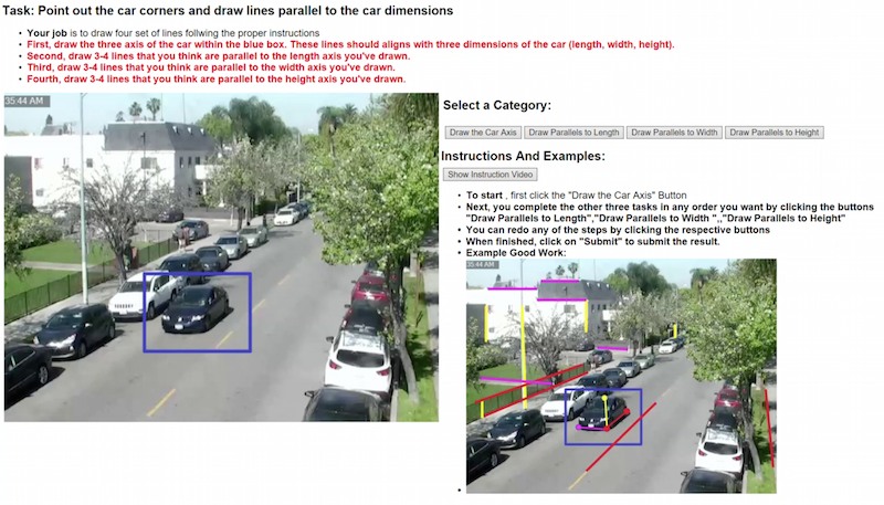
On the other end, we employ a purely crowd-sourced method where each human is tasked with drawing 3-4 lines that are parallel to each of the car axis. An Amazon Mechanical Turk based platform is employed to this end where we combine the annotations from multiple turkers to get better estimate. This is illustrated in Fig. 3. Figure 3a illustrates the amazon mechanical turk based crowdsourcing webpage where each participant is asked to complete 4 tasks with the first task being related to the Car Axis Annotation (CAAn) modules. Figure 3b illustrates the data collected from one person which demonstrated three sets of mutually orthogonal lines pertaining to the vanishing points.
Relative Pose Estimation (ReaPE) This is the last and the pose estimation module in our proposed pipeline. This modules gathers all three types of information i.e., car dimensions, car axis points, and three orthogonal vanishing points and applies (3) to estimate the image center, (6) to estimate the focal length and pixel dimensions. Next, the estimated intrinsic parameters and the vanishing points are used to estimate the rotational matrix. Lastly, we get two different estimates for the translation matrix by employing (10) and (12). We do not use the height direction, as this direction is most erroneous due to different perceptions of different person. On the other hand, the length and width direction of car are more consistent. However, based on the relative location, the car length might be more visible that car width and thus have better accuracy. To get the goodness of both estimates, we compare the pixel length of the car length and width. Whichever is the larger provides better estimate.
V Absolute Localization
V-A Goal
In Section IV, we explained our proposed pipeline to estimate the relative position between an Car visible on the feed of camera and the camera, denoted as . In this section, we detail how the relative location can be translated to a absolute location for the camera, . To this end, we assume that we have the absolute location of at-least one image pixel, typically corresponding to landmarks. Let’s say the pixel location of is . Since, GPS locations does not provide height information, this pixel MUST correspond to a ground location so that the height is 0. Let’s denote the relative location as .
V-B RoadMap
Since we know the the absolute location of the landmark point as well as the relative location, we can use the ground distance between the camera and the landmark, to draw a circular feasible region. Now the challenge is to filter out to one location. The location provides an additional information ve location