Modern and Future Colliders
Abstract
Since the initial development of charged particle colliders in the middle of the 20th century, these advanced scientific instruments have been at the forefront of scientific discoveries in high energy physics. Collider accelerator technology and beam physics have progressed immensely and modern facilities now operate at energies and luminosities many orders of magnitude greater than the pioneering colliders of the early 1960s. In addition, the field of colliders remains extremely dynamic and continues to develop many innovative approaches. Indeed, several novel concepts are currently being considered for designing and constructing even more powerful future colliders. In this paper, we first review the colliding beam method and the history of colliders, and then present the major achievements of operational machines and the key features of near-term collider projects that are currently under development. We conclude with an analysis of numerous proposals and studies for far-future colliders. The evaluation of their respective potentials reveals tantalizing prospects for further significant breakthroughs in the collider field.
I Introduction
Particle accelerators are unique scientific instruments which offer access to unprecedented energy per constituent, using well-focused high density beams of electrons (), positrons (), protons (), antiprotons (), ions, muons (, ), mesons, photons and gamma quanta (), among others Sessler and Wilson (2014); Scharf (1989); Livingston (1954). They have been widely used for physics research since the early 20th century and have greatly progressed both scientifically and technologically since. Analysis of all Nobel-Prize winning research in physics since 1939 nob (2020) — the year the Nobel Prize was awarded to Ernest O. Lawrence for invention of the first modern accelerator, the cyclotron Lawrence and Livingston (1932) — reveals that accelerators have played an integral role in influencing more than a quarter of physics-prize recipients by either inspiring them or facilitating their research. On average, accelerators have contributed to one Nobel Prize for Physics every three years Haussecker and Chao (2011). Four Nobel prizes have directly honored breakthroughs in accelerator science and technology; aside from E.O. Lawrence, John Cockcroft and Ernest Walton received the prize in 1951 for their invention of the eponymous linear accelerator Cockcroft and Walton (1932), and Simon van der Meer in 1984 for conceiving and developing the novel method of stochastic cooling Van Der Meer (1985). To gain an insight into the physics of elementary particles, one accelerates them to very high kinetic energy, lets them strike other particles, and detects products of the ensuing reactions that transform the particles into new particles, such as the Higgs boson, which was discovered in the debris of proton-proton collisions at the Large Hadron Collider (LHC) Bruning and Collier (2007) and celebrated with the 2013 Nobel Prize in Physics Englert (2014); Higgs (2014). Recently, accelerator-based synchrotron radiation sources were instrumental for a number of Nobel-Prize winning research achievements in chemistry and biology, recognized in 1997, 2003, 2006, 2009, and 2012. At present, about 140 accelerators of all types worldwide are devoted to fundamental research Particle Accelerators Around the World . In the United States alone, the Department of Energy (DOE) Office of Science is supporting 16 large accelerator-based user facilities open for basic research — such as colliders, light sources and neutron sources — with a total annual budget for operation and construction exceeding $2B US DOE Office of Science User Facilities . These facilities enable scientific research to be carried out by about 20,000 users from academia, industry, and government laboratories. Europe’s leading particle physics laboratory, CERN, with an annual budget of about 1.15 BCHF 2019 Annual Contributions to CERN budget , operates the world’s largest accelerator complex and brings together 17,000 physicists, engineers, and technicians from more than 110 different countries.
Colliders are the most sophisticated of all accelerator types and employ the most advanced technologies and beam physics techniques to push the envelope of their performance. What makes them the instruments of choice for particle physics is their kinematic advantage of a high center-of-mass energy resulting in larger momentum transfers. Indeed, the center of mass energy (c.m.e.) (also often cited as , the square root of one of the Lorentz-invariant Mandelstam variables in the kinematics of reactions — see, e.g., Perkins (2000)) for the head-on collision of two particles of masses and with energies and colliding at a crossing angle is
| (1) | |||||
where denotes the speed of light.
| Species | , GeV | , m | Years | ||
| AdA | 0.25 | 4.1 | 1964 | ||
| VEP-1 | 0.16 | 2.7 | 1964-68 | ||
| CBX | 0.5 | 11.8 | 1965-68 | ||
| VEPP-2 | 0.67 | 11.5 | 1966-70 | ||
| ACO | 0.54 | 22 | 1967-72 | ||
| ADONE | 1.5 | 105 | 1969-93 | ||
| CEA | 3.0 | 226 | 1971-73 | ||
| ISR | 31.4 | 943 | 1971-80 | ||
| SPEAR | 4.2 | 234 | 1972-90 | ||
| DORIS | 5.6 | 289 | 1973-93 | ||
| VEPP-2M | 0.7 | 18 | 1974-2000 | ||
| VEPP-3 | 1.55 | 74 | 1974-75 | ||
| DCI | 1.8 | 94.6 | 1977-84 | ||
| PETRA | 23.4 | 2304 | 1978-86 | ||
| CESR | 6 | 768 | 1979-2008 | ||
| PEP | 15 | 2200 | 1980-90 | ||
| SS | 455 | 6911 | 1981-90 | ||
| TRISTAN | 32 | 3018 | 1987-95 | ||
| Tevatron | 980 | 6283 | 1987-2011 | ||
| SLC | 50 | 2920 | 1989-98 | ||
| LEP | 104.6 | 26660 | 1989-2000 | ||
| HERA | 30+920 | 6336 | 1992-2007 | ||
| PEP-II | 3.1+9 | 2200 | 1999-2008 | ||
| KEKB | 3.5+8.0 | 3016 | 1999-2010 | ||
| VEPP-4M | 6 | 366 | 1979- | ||
| BEPC-I/II | 2.3 | 238 | 1989- | ||
| DANE | 0.51 | 98 | 1997- | ||
| RHIC | 255 | 3834 | 2000- | ||
| LHC | 6500 | 2669 | 2009- | ||
| VEPP2000 | 1.0 | 24 | 2010- | ||
| S-KEKB | 7+4 | 3016 | ∗ | 2018- |
For many decades throughout the first half of the 20th century, the only arrangement for accelerator experiments involved a fixed-target setup, where a beam of charged particles accelerated with a particle accelerator hit a stationary target set into the path of the beam. In this case, as follows from Eq. (1), for high energy accelerators , . For example, the collision of =7000 GeV protons with stationary protons 1 GeV can produce reactions with of about 120 GeV. A more effective colliding beam set-up, in which two beams of particles are accelerated and directed against each other, offers a much higher center of mass energy of , assuming a typically small or zero crossing angle . In the case of two equal masses of colliding particles (e.g., protons and protons, or protons and antiprotons) with the same energy of 7000 GeV, one obtains or 14 000 GeV. Several machines operate with beams of unequal energies, either because the colliding particles have different masses (electron-proton collisions at HERA) or because of the need to generate new short-lived particles, such as mesons, with a Lorentz boost so as to more easily detect and analyze their decays (asymmetric -factories KEKB, PEP-II, and SuperKEKB).
In total, 31 colliders have so far reached the operational stage (some in several successive configurations) and seven of these are operational now (2019) — see Table 1. These facilities essentially shaped modern particle physics Hoddeson et al. (1997); Ellis et al. (2003); Barger (2018). The idea of exploring collisions in the center of mass system to fully exploit the energy of accelerated particles was first given serious consideration by the Norwegian engineer and inventor Rolf Wideröe, who in 1943 had filed a patent for the collider concept (and received the patent in 1953) Wideroe (1953); Waloschek (2013). This idea was further developed by Donald Kerst Kerst et al. (1956) and Gerry OflNeill O’Neill (1956), and in the late 1950s three teams started working on colliding beams: (i) a Princeton-Stanford group in the US that included William Barber, Bernard Gittelman, Gerry OflNeill, and Burton Richter, who in 1959 proposed building a couple of tangent rings to study Møller scattering (Stanford colliding-beam experiment CBX Barber et al. (1959)); (ii) a somewhat similar project initiated by Gersh Budker in the Soviet Union, where an electron-electron collider VEP-1 was under construction in 1958 G.I. Budker, B.G. Erozolimsky, A.A. Naumov ; and (iii) an Italian group at the Laboratori Nazionali di Frascati, led by Bruno Touschek, which began the design of the first electron-positron collider AdA Bernardini et al. (1960). In the early 1960s, almost concurrently, these first colliders went into operation in the Soviet Union Budker (1967); Levichev et al. (2018), France (to where the AdA had been moved) Bernardini et al. (1964); Bernardini (2004), and the USA Gittelman (1965a); Rees (1986).
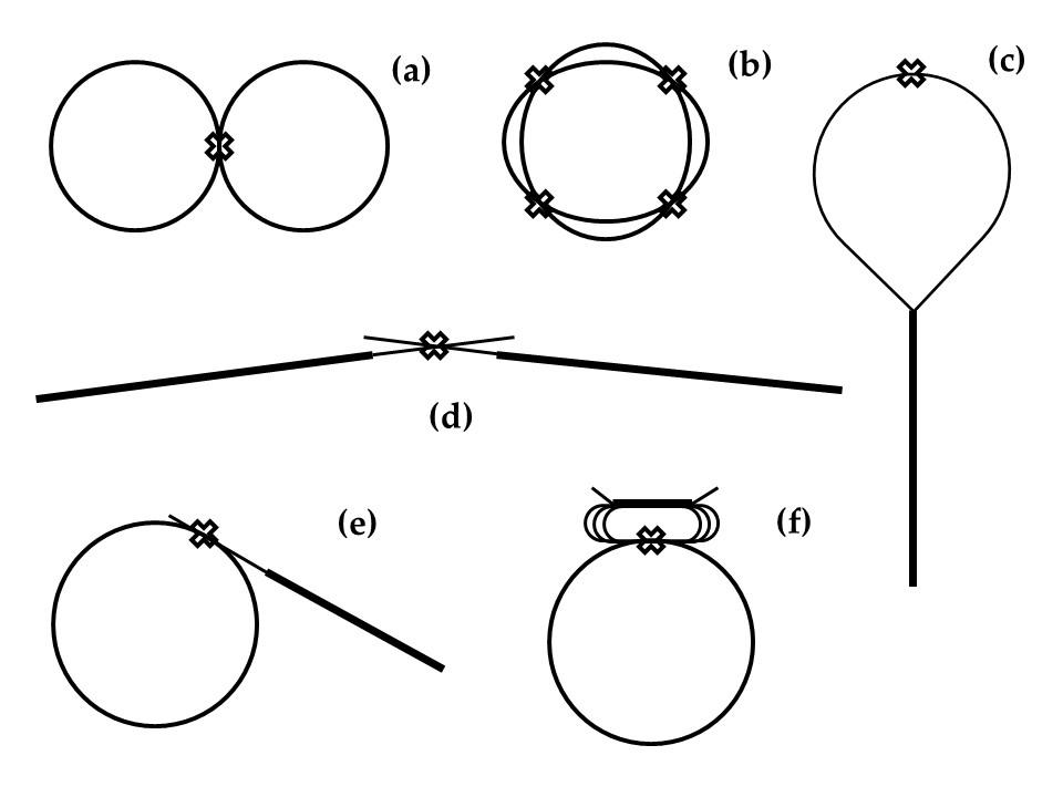
Figure 1 presents the most common arrangements of colliding beams. In storage ring configurations - Fig. 1a and 1b particles of each beam circulate and repeatedly collide. Historically, a single ring was often used for colliding particle and antiparticle beams of equal energy. Modern and future storage-ring colliders (e.g. LHC, DANE, BEPC-II, FCC, CEPC, SppC, etc.) utilize double rings to achieve extremely high luminosity by colliding a large number of bunches. The two rings may store particles of the same type, or particles and their antiparticles, or two different particle types, like electrons and hadrons. In linear colliders, first proposed in Ref. Tigner (1965) and then further developed for higher energy, e.g. in Refs. Amaldi (1976); Balakin and Skrinsky (1979), the two colliding beams are accelerated in linear accelerators (linacs) and transported to a collision point, either with use of the same linac and two arcs as in Fig. 1c, or in a simple two-linac configuration as depicted in Fig. 1d. Other configurations are possible and were considered: e.g., linac-ring schemes as in Fig. 1e or collision of beams circulating in a ring and a few-pass energy recovery linac (ERL) (Fig. 1f).
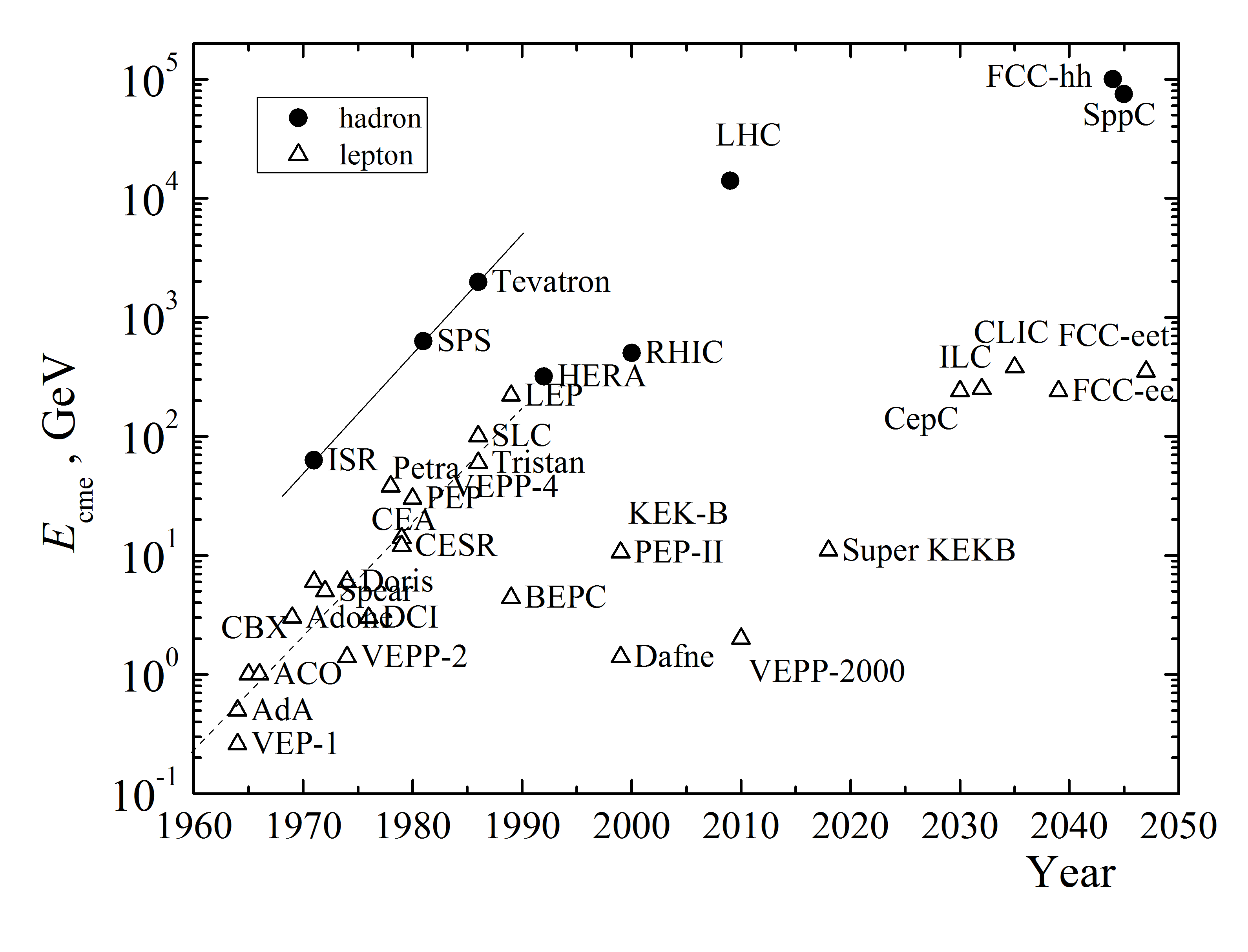
In contrast to other types of accelerators, which have many diverse applications, colliders have exclusively served the needs of frontier particle physics research (or what is nowadays called high-energy physics (HEP) and nuclear physics). The ever-growing demands of particle physics research drove the increase in energy of colliders, as is demonstrated in Fig. 2. In this figure, the triangles represent maximum c.m.e. and the start of operation for lepton colliders (mostly ), while full circles represent hadron (protons, antiprotons, ions, proton-electron) colliders. One can see that until the early 1990s, the c.m.e. increased on average by a factor of ten every decade. Notably, hadron colliders were 10–20 times more energetic (though hadrons are not elementary particles and only a fraction of their energy is available to produce new particles during collisions). Since then, the paths of different colliders diverged: hadron colliders continued the quest for record high energies in particle reactions and the LHC was built at CERN, while in parallel, highly productive colliders called particle factories focused on precise exploration of rare phenomena at much lower energies.
The exploration of rare particle physics phenomena requires not only an appropriately high energy, but also a sufficiently large number of detectable reactions. The number of events of interest is given by the product of the cross section of the reaction under study, , and the time integral over the instantaneous luminosity, :
| (2) |
The luminosity dimension is [length]-2[time]-1. The integral on the right is referred to as integrated luminosity , and, reflecting the smallness of typical particle-interaction cross-sections, or the correspondingly high integrated luminosity required, is often reported in units of inverse pico-, femto- or attobarn, where 1 barn=10-24 cm2, e.g., 1 fb=10-39 cm2. In fixed target mode, luminosity is a product of the extracted high-energy particle flux rate times target density and length. Collider luminosity is defined only by the beam parameters and is critically dependent on beam densities, which are typically orders of magnitude lower than those of liquid or solid targets. Colliders usually employ bunched beams of particles with approximately Gaussian distributions, and for two bunches containing and particles colliding head-on with frequency , a basic expression for the luminosity is
| (3) |
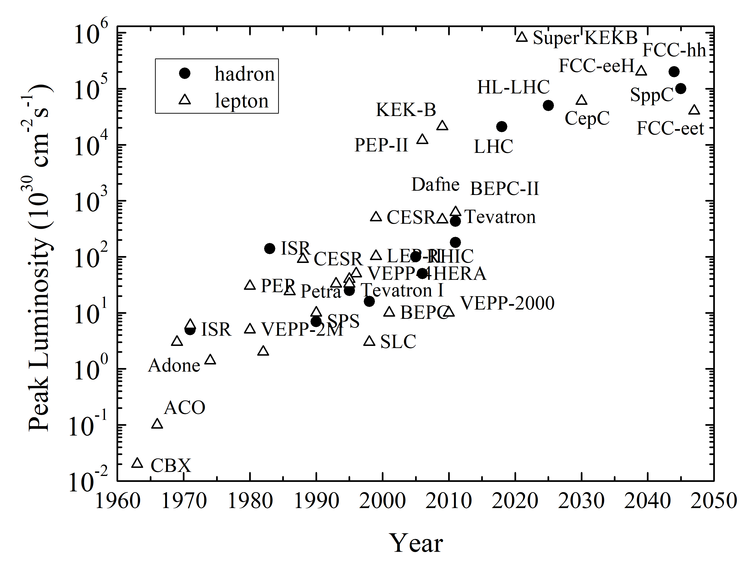
where and characterize the rms transverse beam sizes in the horizontal and vertical directions at the point of interaction (Myers and Schopper, 2013, Ch. 6.4). To achieve high luminosity, one therefore has to maximize the population and number of bunches, either producing these narrowly or focusing them tightly and colliding them at high frequencies at dedicated locations where products of their reactions can be registered by detectors. Figure 3 demonstrates the impressive progress in luminosity of colliding beam facilities since the invention of the method — over the last 50 years, the performance of colliders has improved by more than six orders of magnitude and reached record high values of over cm-2s-1. At such a luminosity, one can expect to produce 5 million events over one year of operation (effectively, about s) for a reaction cross section is 50 picobarn (pb)= cm2. An example process with this magnitude is Higgs particle production at TeV c.m.e. in the LHC De Florian et al. (2016).
Luminosity considerations differ significantly for lepton and hadron colliders. For point-like colliding particles such as leptons, the reach of the collider, defined as the highest mass of a particle that can be produced there, just equals . Due to the “1/” scaling of the Feynman propagator for hard-scattering processes (here, again is the Mandelstam variable, with and denoting the four-momenta of the two incoming particles), the production cross-section of is proportional to Frauenfelder and Henley (1991). To detect new particles of increasing mass, integrated luminosity should increase as . As hadrons are quarkgluon composite objects, the probability of creating a new mass depends on the Quantum Chromodynamics (QCD) parton distribution functions in the nucleon; the corresponding cross sections scale as , where is a sharply falling function Eichten et al. (1984); Quigg (2011a). In consequence, the collider mass reach is a strong function of and a rather weak function of Salam and Weiler (2017). For example, with a rough approximation of , the mass discovery reach of a hadron collider scales as Teng (2001). This peculiar characteristics of very-high-energy hadron colliders has been proven again and again in the past (see the next section), and it is often invoked to qualify them as “discovery machines”. In general, the key components of the experimental program toward understanding of the structure of matter are particle detectors and accelerators. Remarkable advances in the detector technology and key challenges of the detectors for future hadron and lepton colliders are outside the scope of this review and can be found in review publications and textbooks such as (Tanabashi et al., 2018, Ch. 34), Green (2000); Grupen and Shwartz (2008), (Ellis et al., 2019, Ch. 11).
Over the past five decades, the quest for higher energy particles led to some five orders of magnitude boost of collider energies and an even greater increase in their luminosities — see Figs. 2 and 3. Simultaneously, the size, complexity and cost of colliding beam facilities have also increased. Modern colliders employ numerous technologies for tunneling, geodesy and alignment, power converters and power supplies, ultra-high vacuum systems, particle sources, injection and extraction systems, cooling water and cryogenic cooling, beam diagnostics, accelerator control, personnel safety and machine protection, among others. While at the dawn of accelerator and collider technology, most of these required dedicated and often pioneering developments, nowadays many such technologies are widely available from specialized industries. Still left almost solely to the pursuit of accelerator engineers and scientists are the “core technologies” required for accelerating particles to high energies — normal- and superconducting radio-frequency (RF) acceleration systems, and normal- and superconducting accelerator magnets — and “beam physics techniques” to attain the necessary beam qualities such as intensity, brightness and sometimes polarization, including beam cooling, manipulation and collimation, the production of exotic particles like antiprotons or muons, mitigation of beam instabilities, and countermeasures against beam-size blow up caused by space-charge (SC) and beam-beam effects, or intra-beam scattering (IBS), among others. The energy reach of a collider is mostly defined by core accelerator technologies, while its luminosity is grossly dependent on the sophistication of beam physics techniques.
Being arguably the biggest and the most technologically advanced scientific instruments, colliders were and remain costly, often at the brink of financial and political affordability. That makes them prone to various risks and, in the past, several have been terminated, even after the start of construction. Most notable in this respect are energy frontier hadron colliders. In 1983, the construction of the 400 GeV c.m.e. ISABELLE collider (briefly renamed CBA) at the Brookhaven National Laboratory in the USA was stopped Month (2003); Crease (2005a, b), and in the early 1990s two other flagship projects were terminated: the 6 TeV c.m.e. proton-proton complex UNK Yarba (1990); Kuiper (1994) in Protvino, Russia, and the 40 TeV c.m.e. proton-proton Superconducting Super Collider (SSC) in Texas, USA, in 1993 Wojcicki (2009); Riordan et al. (2015). Notwithstanding the above, advances in core accelerator technologies — including the SC magnet developments for ISABELLE/CBA, UNK and SSC — have led to substantial reductions in collider cost per GeV Shiltsev (2014). This progress, together with the growing strength of the high-energy particle physics community, enabled development of frontier machines, such as the currently operational multi-billion dollar LHC. Even larger $10B-scale future collider projects are generally considered feasible (see the following sections).
On average, the colliders listed in Table 1 operated for 13 years, with many remarkable facilities operating for even twice that time (Adone, VEPP-2, CESR, Tevatron, VEPP-4M, BEPC-II). Contrary to other research accelerators, such as light sources, where user groups and experiments are numerous and each might take as little beam time as weeks or a few days, over their lifetime most of these colliders served just one, two, or four permanently installed particle detector experiments surrounding the beam collision points. For example, PETRA, TRISTAN, LEP, RHIC and the LHC each had (or have) four main collision points and detectors Fernow and Fernow (1989); Hauptman (2011). The colliding-beam facilities usually consist of several machines needed to prepare and accelerate the beams and are generally quite complex, featuring several layers of structural hierarchy — numerous primary elements, combined in technical subsystems, composed in individual accelerators, highly interconnected and working synchronously as one complex. The largest of these require hundreds of highly skilled personnel for operation, including a sizable number of PhD physicists. The complexity and scale of the colliders result in substantial lengths of time, usually many years, being required for full commissioning and for attaining the ultimate luminosities Shiltsev (2011). It is characteristic for colliders to continuously proceed through a series of minor operational improvements, interleaved with a few major upgrades, and to see their performance increase all through their lifetimes.
Particle physics has not yet fully exploited the potential of the colliding-beam technique and is largely betting its future on it Ellis (2018). The current consensus is that “…no other instrument or research programme can replace high-energy colliders in the search for the fundamental laws governing the universe” Giudice (2019).
In Section II below, we briefly outline the development of colliders and the corresponding core accelerator technologies and beam physics techniques. Seven currently operational collider facilities will be described and discussed in Section III. The next generation of colliders, believed to be technically feasible and affordable, and which could be constructed over the next two or three decades, is the subject of Section IV. Finally, in Section V, we assess opportunities offered by emerging accelerator technologies and attempt to look beyond the current horizon and outline possible changes in the collider paradigm which might enable far-future, ultimate colliders.
II Development of colliders
Modern and future colliders are extensively based on the accelerator technology and beam physics techniques developed and appraised by their predecessors. In this section, we introduce and elaborate on major collider issues from a historical perspective. More detailed considerations and comprehensive lists of references can be found, e.g., in Chao et al. (2013a); Myers and Schopper (2013); Myers and Brüning (2016).
In an accelerator, charged particles gain energy from an electric field, which usually varies in time at a high frequency ranging from 10s of MHz to 10s of GHz. The accelerating field gradients in RF cavities are usually orders of magnitude higher than in direct-current (DC) systems; RF cavities are, therefore, commonly used in colliders. At present, the highest beam accelerating gradients ever achieved in operational machines or beam test facilities are some MV/m in 12 GHz normal-conducting (NC) RF cavities Senes et al. (2018) and 31.5 MV/m in 1.3 GHz superconducting RF (SRF) ones Broemmelsiek et al. (2018). In a linear-collider arrangement, illustrated in Figs. 1c, d and e, the beam energy is the product of the average accelerating gradient and the length of the linac :
| (4) |
where denotes the elementary (electron) charge, assuming the acceleration of singly charged particles like electrons or protons. For example, reaching 1 TeV energy requires either 10 km of NC RF accelerator or 30 km of SRF linac, if the RF cavities occupied all available space — which they do not. Cost considerations (see below) often call for minimization of RF acceleration, e.g., through repeated use of the same RF system which in that case would boost the energy in small portions per turn every time a particle passes through the total cavity voltage . Such an arrangement can be realized both in the form of circular colliders (Fig. 1a, b), which have proven extremely successful, and also through novel schemes based on ERLs (Fig. 1f). Circular colliders are most common; here, the momentum and energy of ultra-relativistic particles are determined by the bending radius inside the dipole magnets, , and by the average magnetic field of these magnets:
| (5) |
In such a scheme, the field needs to be synchronously increased to track particle energy gains after each passage through the accelerating RF cavities. Such synchrotron conditions allow the beam orbit to remain inside the rather limited space provided by the accelerator beam pipe passing through the magnet apertures. The maximum field of NC magnets is about 2 Tesla (T), due to the saturation of ferromagnetic materials, and while this is sufficient for lower energy colliders, such as most storage rings, it is not adequate for frontier-energy hadron (or muon) beams, because of the implied need for excessively long accelerator tunnels and prohibitively high total magnet power consumption. The development of superconducting (SC) magnets that employ high electric current carrying Nb-Ti wires cooled by liquid helium below 5 K, opened up the way towards higher fields and to hadron colliders at record energies Tollestrup and Todesco (2008). The latest of these, the 14 TeV c.m.e. LHC at CERN, uses double bore magnets with a maximum field of 8.3 T at a temperature of 1.9 K, in a tunnel of km circumference (dipole-magnet bending radius m).
II.1 Basic technologies and beam physics principles
II.1.1 Magnets and RF structures
Magnets form the core of all types of colliders. Besides bending magnets, several other field shapes are required in order to focus and control the beams and manipulate beam polarization. Accelerator magnets typically are long (up to a few m), and feature transversely small apertures (few cm), which accommodate the beam vacuum pipes. The magnetic field components are normally oriented in the plane of the magnet cross section. In such a 2D configuration, the most common representation of the field is given by a complex multipole expansion:
| (6) |
where and represent the normal and skew multipole components of the field, and signifies the number of poles. For example, in an ideal horizontally deflecting, normal dipole magnet (), we have and .
For an ideal quadrupole magnet (), the fields are , . So this type of magnet can be used as a focusing element as it deflects a particle proportionally to its transverse offset (or ) from the magnet axis. Namely, to first approximation, we have , where is the slope of the particle trajectory (horizontal momentum divided by the longitudinal momentum ), the change in slope after passing through the quadrupole, and the normalized strength of a quadrupole of length , which is given by , with the magnetic rigidity .
Higher order multipole magnets, such as sextupoles () and octupoles (), are also widely used, e.g., to control an accelerator’s chromaticity — the dependence of its focusing property on particle momentum — and for beam stabilization, respectively. Other commonly employed magnets are wigglers and undulators, sequences of short dipole magnets with alternating polarity, which yield a periodic field variation along the beam trajectory, causing the beam to wiggle and to lose energy, emitting electromagnetic radiation Clarke (2004). High-field, few T solenoids are commonly deployed in collider detectors Yamamoto (2003); solenoid magnets are also used for spin rotation and beam polarization control Barber et al. (1984); and for focusing of mostly lower-energy beams, e.g., in electron coolers Parkhomchuk and Skrinsky (2000) and injectors Carlsten (1995).
Collider beam dynamics is highly sensitive to magnet field quality, understood as the relative deviation of the actual field from its ideal design value, and requires the unwanted components to be of the level of a few of the main field, e.g., of the corresponding primary dipole or quadrupole field, and to be even smaller for a few special, strong magnets used to ultimately focus or transversely compress the beams at the collider’s interaction points (IPs). In normal-conducting (NC) magnets, a steel or iron yoke is employed to direct and shape the magnetic field inside the magnet aperture, so that the field quality is usually assured by the proper shaping of the magnet poles Tanabe (2005). For field levels above 1.7–2.0 T, as are typical for NC magnets, such an approach no longer works. However, significantly higher fields can be obtained with superconducting (SC) magnets. In SC magnets, the iron of the yoke does not play a major role in field formation. Instead, the achievement of the target field quality requires a conductor-coil placement accuracy and position stability of less than a few dozen micron, which is to be obtained while the coil is subjected to enormous magnetic forces, sometimes exceeding a million Newton per meter Mess et al. (1996) (Myers and Schopper, 2013, Ch.8.1).
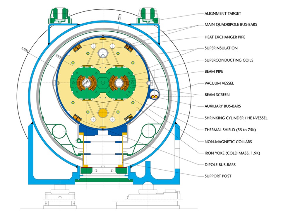
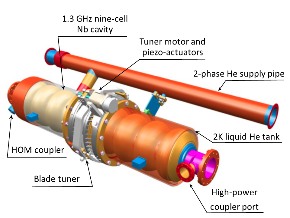
In addition, ramping the SC magnets induces so-called persistent currents inside the superconducting cables, which can result in dangerous systematic sextupole field components of order (where denotes a reference radius for the good field region, typically chosen as about 2/3 of the magnet’s aperture) Tollestrup and Todesco (2008). These and other time-dependent effects require sophisticated systems of weak, but numerous, corrector magnets, adding to the complexity of collider operation, while assuring its efficiency. There are many other difficulties related to the operation of SC magnets, such as the need for cooling by liquid helium, quench detection and protection, alternating-current (AC) losses, and the careful control of the mega- to giga-joules of stored magnetic field energy; all of these have been generally resolved and do not outweigh the major advantages of superconductive systems, namely, a few orders of magnitude lower electric wall-plug power consumption and the ability to generate much higher magnetic fields in Nb-Ti based magnets, of up to 9 T, as demonstrated in the Tevatron (4.5 T), HERA (4.7 T), RHIC (3.5 T) and LHC (8.3 T). Even higher fields, of up to 12–16 T, can be achieved with Nb3Sn conductor Schoerling and Zlobin (2019), and over 20 T are expected with certain high temperature superconductors (HTS) Rossi and Bottura (2012). It should be noted that the field values cited above are lower than the critical fields of these materials, since the operation of systems of many (hundreds to thousands) accelerator magnets demands significant margins in temperature and critical current to achieve an acceptable stability in an environment characterized by powerful heat sources, due to beams circulating just a few cm away from SC coils (irradiation by local beam loss, vacuum pipe heating due to electron cloud effects and image currents, synchrotron radiation, etc.) — see Fig. 4.
The RF systems of colliders are mostly needed to increase or maintain the particles’ energy using time-varying longitudinal electric fields. They typically operate at carefully preselected frequencies in the range of several tens of MHz to tens of GHz and consist of three main elements — power converter, RF amplifier, and RF cavity — together with control loops (low level RF subsystem, including the master oscillator) and ancillary systems: water cooling, vacuum, and cryogenics in the case of superconducting RF (SRF) cavities. The RF system is essentially a device that transforms electrical energy taken from the grid into energy transferred to a beam of particles in three major steps, each with its own technology and efficiency: 1) the transformation of AC power from the electric grid (alternate, low voltage, high current) to DC power (continuous, high voltage (HV), low current) that takes place in a power converter with some 90% efficiency; 2) the transformation of the DC power into RF power (high-frequency) that takes place in an RF power source: RF tube, klystron, transistor, etc., with efficiency in the range of 50–70% or more, depending on the specific device and mode of operation (continuous wave (CW) or pulsed); 3) transformation of RF power into the particle beam power gain that takes place in the gap of an accelerating cavity, with efficiencies that may reach 30% or 50% in a pulsed NC or SC linac Bailey (2012) or be approximately 100% in case of a continuous wave (CW) SRF system for a storage ring. Thanks to cost saving considerations, all these efficiencies have been constantly improving with increasing RF power demands, which for large modern and future colliders can be as high as dozens or even several hundreds of MW Delahaye (2018).
The energy gain of a particle traversing an RF cavity is
| (7) |
where , , , and denote the cavity’s electric field, accelerating voltage, frequency and phase, respectively, and is the particle’s velocity, usually parallel to the accelerating field, at the time of passage . For synchrotrons and storage rings, the condition of synchronicity over subsequent acts of acceleration calls for the RF frequency to be a harmonic of the revolution frequency , with the integer known as the harmonic number. The RF power supplied to the cavity from the source goes into the increase of beam power, , and into sustaining an accelerating field that otherwise would decay, , due to the finite cavity surface conductivity:
| (8) |
Here, is the beam current and is the so-called shunt impedance (the resonant resistance of an equivalent RCL circuit) is the product of the RF cavity’s quality factor , related to the power dissipation on the cavity surface, and a factor , depending only on the cavity geometry. Typical values for NC cavities are in the range of some 104, while they can reach a few 10 in SRF cavities Martinello et al. (2018). The factor , which is independent of the cavity size and of the surface resistance, is commonly used as a figure of merit — see, e.g. Padamsee et al. (2008). It typically varies between 196 Ohm per resonant cell, obtained for a TM mode pillbox cavity with minimal opening for beam passage, and some 100 Ohm per cell for large aperture elliptical cavities, such as used in SRF systems.
The largest linac built to date was a 3 km long linac at the Stanford Linear Accelerator Center (SLAC), which operated NC copper structures at a frequency of 2.856 GHz (corresponding to RF wavelength of =10.5 cm). It provided a total of 50 GeV acceleration in one pass, with average gradient of about 21 MV/m Erickson et al. (1984). Only 80 kW of 10 MW of total RF power went into the power of the two colliding beams Phinney (2000); Lavine (1992).
Circular colliders are much more efficient due to repetitive energy transfer from RF cavities to beams over many turns, but at highest energies they face a serious impediment in the form of synchrotron radiation. The latter causes an energy loss per turn of Sands (1970)
| (9) |
which increases with the fourth power of energy and scales with the inverse of the bending radius. Inserting numerical values for electrons, the energy loss of a particle during one revolution becomes 0.089 [MeV/turn] [GeV]/[m]. Even for the largest circumference collider LEP with an average bending radius of about 3.1 km, maintaining maximum beam energy at 104.5 GeV required continuous wave (CW) operation of the 353.2 MHz RF system with a voltage of 3.4 GeV per turn, to compensate for about 23 MW total synchrotron radiation beam power loss Brandt et al. (2000). Adequately, the final LEP RF system consisted of 272 superconducting Nb sputter-coated Cu cavities and 16 solid Nb cavities, with an average gradient of 5–6 MV/m, and 56 lower voltage normal-conducting Cu cavities, with a gradient of 1.5 MV/m, together provided a maximum total RF voltage of GV. In the last year of LEP operation the 288 SRF cavities were powered by 36 klystrons with an average power of 0.6 MW Assmann et al. (2002a); Brown et al. (2001). The pure RF-to-beam-power efficiency was . An effective “RF-to-beam-power efficiency” of about 75% was computed by taking into account the additional cryogenic power needs resulting from both RF-related heating and static heat load of the cryostat, in conjunction with the low cooling efficiency at cryogenic temperature Weingarten (1996)). Also adding AC-to-DC conversion and LEP klystron efficiencies Butterworth et al. (2008), plus waveguide losses, the total wall-plug-to-beam-power efficiency, including cryogenics, was close to 50%.
Besides beam acceleration, RF systems are also employed for various other beam manipulations, such as longitudinal bunching, bunch compression, splitting, coalescing and flattening Minty and Zimmermann (2013) and, in some cases, to provide a time-varying transverse deflection to particle bunches in crab cavities for linear and circular colliders Palmer (1988); Oide and Yokoya (1989); Sun et al. (2009), as streaking devices for time-varying diagnostics Akre et al. (2002), and for bunch separation or bunch combination, e.g. as RF deflectors in the drive-beam complex of the proposed CLIC linear collider and its past CLIC Test Facility 3 Marcellini and Alesini (2004).
Synchrotron-radiation power of protons is smaller than for electrons by a significant factor at the same energy — see Eq. (9) — but it can still become a significant concern in highest-energy, high-current SC accelerators like the LHC. The reason is that synchrotron radiation leads to heating and outgassing of the beam vacuum pipe. The former poses problems for the cryogenic system of the SC magnets, while the latter may impede attainment of vacuum gas pressures of 1–10 nTorr or better, that are needed to guarantee sufficiently long lifetimes of the continually circulating beams. Fortunately, these technological challenges have been successfully resolved in modern colliding beam facilities Barron (1985); Lafferty (1998), (Myers and Schopper, 2013, Ch.8.3, Ch.8.5).
For many modern colliders, especially for hadron colliders and linear colliders, the costs of core accelerator components, magnets and RF structures, dominate construction costs, followed by the costs for tunnels, electric power infrastructure and auxiliary systems for ultra-high vacuum, cryogenics, beam control and stabilization, among others. The growing demands for higher-energy beams have motivated a large segment of the accelerator community to search for, and to develop, new cost-effective technological concepts and advances.
II.1.2 Beam dynamics
Given the enormous and highly concentrated power carried by high energy particle beams, the main concern of beam dynamics in colliders is stability. Below, we briefly introduce major physics phenomena affecting the dynamics of individual particles in accelerators, both single high-intensity beams of many particles moving together, and also colliding beams. Comprehensive definitions and explanations of these subjects can be found in textbooks Edwards and Syphers (2008); Peggs and Satogata (2017); Lee (2018); Chao et al. (2013b).
While a reference particle proceeds along the design trajectory (reference orbit) mostly determined by transverse dipole fields, other particles in the bunch are kept close by through the focusing effect of quadrupole fields. Generally following Edwards and Syphers (2008), let us assume that the reference particle carries a right-handed Cartesian coordinate system, with the co-moving -coordinate pointed in the direction of motion along the reference trajectory, (with the reference particle velocity, and time). The independent variable is the distance of the reference particle along this trajectory, rather than time , and for simplicity this reference path is taken to be planar. The transverse coordinates are (horizontal) and (vertical), where defines the plane of the reference trajectory.
Several time scales are involved, and this is reflected in the approximations used in formulating the equations of motion. All of today’s high-energy colliders are alternating gradient synchrotrons Chao et al. (2013a) and their shortest time scale is set by so-called betatron oscillations. The linearized equations of motion of a particle displaced from the reference trajectory are:
| (10) |
where the magnetic field is only in the direction, contains only dipole and quadrupole terms, and is here treated as static in time, but -dependent. We take into account the Maxwell equation in vacuum to eliminate , using the relation . The radius of curvature due to the field on the reference orbit is (); and are the particle’s total momentum and charge, respectively. The prime denotes .
The equations for and are those of harmonic oscillators but with a restoring force periodic in , that is, they are instances of Hill’s equation Magnus and Winkler (2013). The solutions are:
| (11) | |||||
| (12) |
where the action is a constant of integration, , and the envelope of oscillations is modulated by the amplitude function , commonly called the -function. A solution of the same form describes the motion in . The betatron oscillation phase advances according to ; that is, also plays the role of a local wavelength of oscillations along the orbit. An extremely important parameter is the tune, , which is the number of such oscillations per turn about the closed path:
| (13) |
While the integer part of the tune [] generally characterizes the extent of the focusing lattice, it is the fractional part of the tune that needs to be well defined and controlled by the machine operators in order to stay away from potentially detrimental resonances, which may occur under conditions of , where and are integers. For example, for the LHC a combination of horizontal and vertical tunes — also called the working point — equal to ()=(64.31, 59.32) has been selected, such that resonances up to the order of or are avoided Gareyte (1999); Persson et al. (2017a). These resonances are driven by high order multipole components of the fields in the magnets if , by self-fields of the beam, or by the electromagnetic fields of the opposite bunch. Normally, the nonlinear components are very weak compared to linear ones . However, when the nonlinear resonance condition is encountered, the amplitudes of particle oscillations could grow over the beam lifetime, resulting in the escape of the particles to the machine aperture, in the increase of the average beam size, or in both; either of these are highly undesirable phenomena. Careful analysis of nonlinear beam dynamics is instrumental in determining and optimizing the dynamic aperture, which is defined as the maximum amplitude of a stable particle motion Wiedemann (2012).
Neglecting for now all non-linear effects and considering only the linear dynamics, the beta-function is well defined and satisfies the following equation:
| (14) |
In a region free of magnetic fields, such as in the neighborhood of a collider interaction point (IP), usually occupied by particle detectors, a symmetric solution of Eq. (14) is a parabola:
| (15) |
where, in this case, denotes the longitudinal distance from the IP. The location of the beam waist usually coincides with the IP and corresponds to the minimum value of the -function ; the asterisk is used to indicate IP parameters. Of course, a focusing force is needed to prevent the amplitude from growing. In the case of the widely used alternating gradient periodic focusing lattice, consisting of a sequence of equally-spaced quadrupoles with a magnetic field gradient equal in magnitude, but alternating in sign (“focusing quadrupole - drift space - defocusing quadrupole - drift space” — known as a FODO cell), Eq. (14) has stable periodic solutions in both planes provided that the focal length of the quadrupoles is longer than half the lens spacing , i.e., (where is the length of the quadrupole magnet, here assumed to be much shorter than the cell length ). In that case, the amplitude functions have maxima at the focusing quadrupoles and minima at the defocusing ones, equal to, for example, in the case of , which corresponds to a betatron phase advance per FODO cell.
Expressing in terms of yields
| (16) |
with . In a periodic system, these Courant-Snyder parameters Courant and Snyder (1958) are usually defined by the focusing lattice; in a single pass system such as a linac, the parameters may be selected to match the - distribution of the input beam.
For a given position in the ring, the transverse particle motion in phase space describes an ellipse, the area of which is , where the horizontal action is a constant of motion and independent of . If the interior of that ellipse is populated by an ensemble of non-interacting particles, that area, given the name , is constant over the trajectory as well and would only change with energy. In a typical case of the particle’s energy change rate being much slower than betatron motion, and considering a Hamiltonian system (i.e., a hadron collider or a linear collider, either without synchrotron radiation), the adiabatic invariant is conserved, and given that for small angles , it is common practice to consider an energy-independent normalized emittance that is equal to the product of the emittance and relativistic factor and denoted by . For a beam with a Gaussian distribution in , average action value and standard deviations , and , the definition of the normalized emittance is
| (17) |
with a corresponding expression for the other transverse direction, . The angular brackets denote an average over the beam distribution. For 1D Gaussian beam, 95% of the particles are contained within phase space area of . Normalized beam emittances are conserved over the acceleration cycle in linear, static focusing lattices , and consequently, one would expect the same at the hadron (or linear) collider top energy as the one coming from the very initial low energy particle source, such as the duoplasmotron Brown (2004); Wolf (2017) (or photoinjector / damping ring). Unfortunately, that is rarely the case as many time-varying or non-linear phenomena come into play; some of the more important ones are briefly discussed in Subsection II.1.3.
In an storage ring, the normalized emittance is not preserved during acceleration, but at each energy the beam’s equilibrium emittance is determined by the effect of synchrotron radiation as a balance between radiation damping and quantum excitation Sands (1970). In this case, for a constant accelerator optics, the normalized emittance increases with the third power of the beam energy.
As for the description of a particle’s longitudinal motion, one takes the fractional momentum deviation from that of the reference particle as the variable conjugate to . The factors and in Hill’s equations (11) are dependent on momentum , leading to a number of effects: first, the trajectory of off-momentum particles deviates by , where the dispersion function is determined by the magnetic lattice and is usually positive, periodic, and of the order of . Second, the radius of curvature and orbit path-length vary with the momentum and, to first order, are characterized by the momentum compaction factor :
| (18) |
Energy deviations also result in changes of machine focusing lattice properties and variations of the particle tunes, characterized by the chromaticity . The natural chromaticity due to energy dependence of the quadrupole focusing is large and negative (). Corresponding chromatic tune variations even for relatively small energy deviations – can become unacceptably large. To assure transverse particle stability, usually the chromaticity is partially or fully compensated by additional sextupole magnets placed at locations of non-zero dispersion.
RF electric fields (Eq. (7)) in the direction provide a longitudinal focusing effect. This is also known as the phase stability principle, which historically was important for the development of the synchrotron concept Veksler (1944); McMillan (1945). The frequency of such longitudinal synchrotron oscillations is (expressed in units of revolution frequency , to become the synchrotron tune )
| (19) |
where again denotes the RF harmonic number. The synchrotron tune determines the amplitude of longitudinal oscillations for a particle with an initial momentum offset via
| (20) |
Similarly to the case of transverse oscillations, the area of the longitudinal phase space , or , encircled by a moving particle is an adiabatic invariant, and the corresponding normalized longitudinal emittance proportional to the product of rms bunch length and rms momentum spread is a generally conserved quantity in hadron accelerators and also in linear accelerators. In the case of lepton storage rings, synchroton radiation determines the relative momentum spread, which grows with the square of the beam energy Sands (1970), and the corresponding bunch length follows from Eq. (20). In hadron synchrotrons, the longitudinal emittance is often intentionally blown up during acceleration, so as to preserve longitudinal beam stability Baudrenghien et al. (2011).
Longitudinal oscillations are the slowest of all the periodic processes which take place in the accelerators. For example, in the LHC, the frequency of synchrotron oscillations at the top energy of 7 TeV is about Hz, the revolution frequency is 11.3 kHz, the frequency of betatron oscillations is about =680 kHz and the RF frequency is MHz ().
It should be noted that longitudinal motion is practically absent in linacs. In the absence of bending dipoles, dispersion is zero and so are the momentum compaction factor and the synchrotron tune . As a result, in a linac ultrarelativistic particles barely change their relative positions during acceleration despite significant energy spread — see Eq. (20).
II.1.3 Beam dynamics impediments to and evolution of luminosity
For further discussion, the basic Eq. (3) for luminosity is now re-written in terms of normalized transverse emittances Eq. (17) and the amplitude functions at the IP as:
| (21) |
Here, signifies either the repetition rate of a linear collider or of a circular one; for simplicity we assume equal bunch populations in two Gaussian beams with bunches each, with equal and round cross sections at the IP , , with . The numerical factor accounts for geometrical reduction in luminosity Hirata (1995) due to the final bunch length with respect to and due to a crossing angle at the IP . The former, also referred to as hourglass effect, is caused by the increase in transverse beam sizes as one proceeds away from the IP, where grows parabolically, as in Eq. (15). Thus, for round beams, the hourglass effect lowers the contribution to luminosity from such locations by
| (22) |
where Lee (2018), and also leads to a harmful modulation of the beam-beam tune shift (see later) at twice the synchrotron frequency.
In the case of a nonzero crossing angle, assuming small , the factor is equal to Napoly (1993):
| (23) |
The factor rarely drops below 0.5 for the majority of colliders, unless it is specifically required by physics processes under study, as in Bogomyagkov et al. (2018). Thanks to the additional focusing effect during the beam-beam collision, the factor can also be larger than , e.g. up to about a value of 2 (“dynamic beta” along with “dynamic emittance” effects in circular colliders Furman (1994); Otboyev and Perevedentsev (1999), and “disruption enhancement” in linear colliders Yokoya and Chen (1992)).
Naturally, to achieve high luminosity, one has to maximize the total beam populations with the lowest possible emittances, and collide the beams at high frequency at locations where the focusing beam optics provides the lowest possible values of the amplitude functions , the so-called low-beta insertion Robinson and Voss (1966). The latter requires sophisticated systems of strong focusing elements, sometimes occupying quite a significant fraction of the collider’s total length Levichev (2014). The lowest is determined by the maximum field gradients and apertures in the interaction region (IR) magnets and the effectiveness of compensation of chromatic and non-linear aberrations. The quest for maximum intensities and lowest emittances is limited by a number of important and often interdependent effects which affect either incoherent (single particle) dynamics or the dynamics of the beam as a whole (coherent effects).
Examples of incoherent effects are particle losses caused by scattering at a large angle or with a large energy loss, so that either the particle’s amplitude , or its dispersive position deviation physically exceeds the available transverse aperture, usually set by collimators (otherwise, by the vacuum chamber and magnet apertures). This can be due to residual vacuum molecules near the beam orbit or Compton scattering off thermal photons Telnov (1987), due to Coulomb scattering on other particles within the same bunch (Touschek effect) Bernardini et al. (1963), or due to collisions with opposite beam particles and fields, such as inelastic interaction of protons, Bhabha scattering , or radiative Bhabha scattering (Chao et al., 2013a, Ch.3).
Particles can also get lost on the aperture as a result of much slower mechanisms of diffusion caused either by the above processes with smaller scattering amplitudes, but stochastically repeated many times, such as multiple Coulomb intrabeam scattering Piwinski (1988); Bjorken (1983); Piwinski et al. (2018), by external noises such as ground motion or magnetic field fluctuations Levedev et al. (1994), or via chaotic mechanisms like Arnold diffusion, modulational diffusion, or resonance streaming in non-linear fields, enhanced by minor tune modulations Zimmermann (1994). Diffusion is characterized by the action dependent coefficient and leads to a slow evolution of the beam distribution function according to the diffusion equation
| (24) |
and, consequently, to a change (normally an increase) in the average action . For an ensemble of particles, the corresponding beam emittance growth is given by
| (25) |
where the additional second term accounts for beam cooling or damping of particle oscillations. This term appears in the presence of a reaction force opposite to particle momentum if, on average, the corresponding dissipative particle energy loss is compensated for by external power Skrinsky and Parkhomchuk (1981); Parkhomchuk and Skrinsky (2008).
In the case of electron or positron storage rings, such cooling occurs naturally due to synchrotron radiation (Eq. (9)) and it fully determines equilibrium emittance according to Eq. (25) through a balance between radiation damping and excitation of oscillations by random radiation of individual photons Sands (1970); Wiedemann (2003). Four other methods of beam cooling have been developed and successfully employed to attain low emittances, namely electron cooling Budker (1967); Parkhomchuk and Skrinsky (2000); Nagaitsev et al. (2006) and stochastic cooling of heavy particles (ions and antiprotons) Van Der Meer (1985), (Lebedev and Shiltsev, 2014, Ch.7), laser cooling of ion beams Schröder et al. (1990); Hangst et al. (1991); Lauer et al. (1998), and, in a proof-of-principle experiment, the ionization cooling of muons G.I.Budker (1970a); Neuffer (1983); Adams et al. (2019).
The most prominent coherent effects arise from electric and magnetic forces of the opposite bunch at the IPs, characterized by a dimensionless beam-beam parameter :
| (26) |
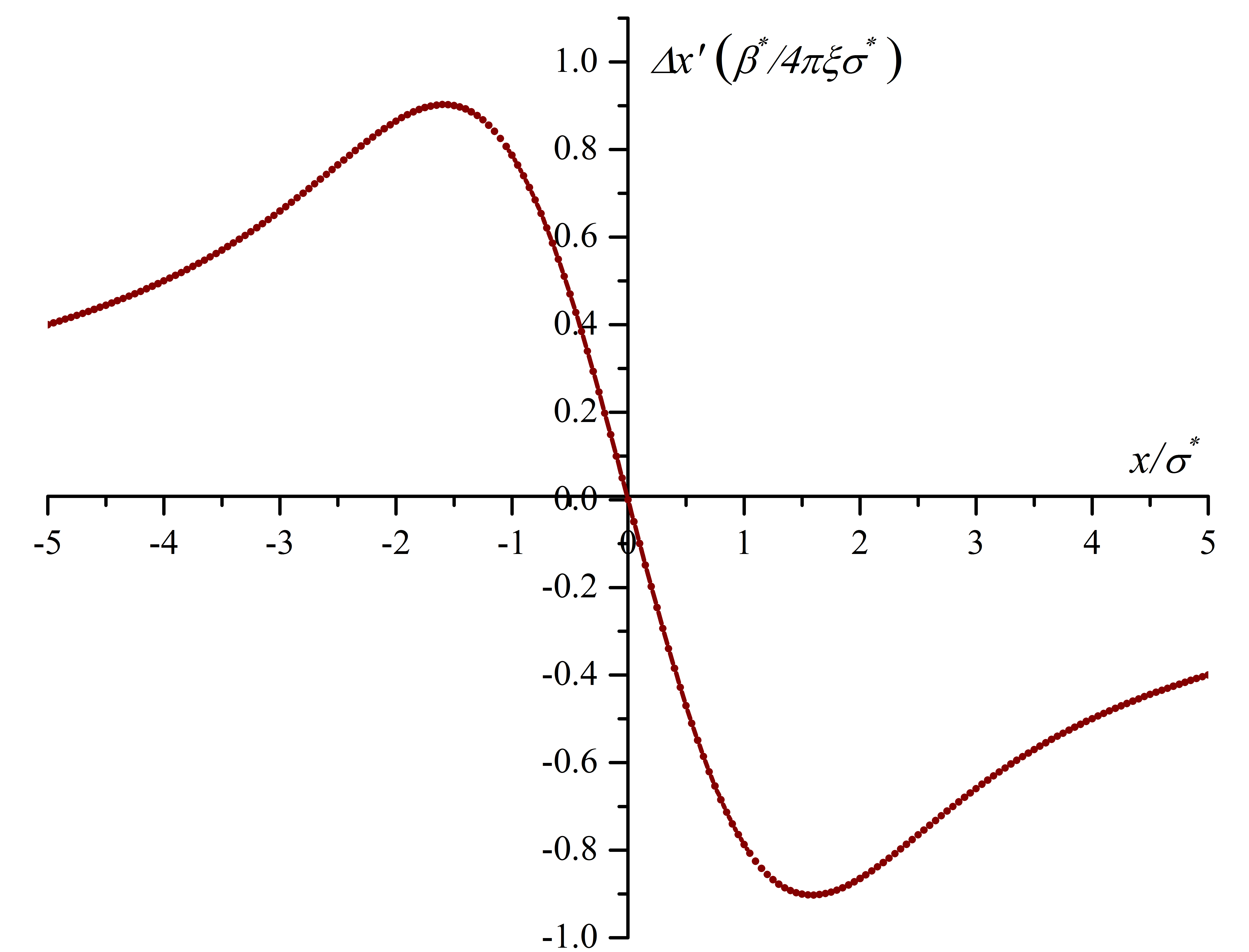
where is the classical radius of the colliding particle (with charge and mass ) Chao (1985). The beam-beam parameter is roughly equal to the betatron tune shift experienced by small amplitude particles — positive in the case of opposite charge beams, like , and negative for same charge beams as in collisions Pieloni and Herr (2013). It also describes the maximum angular beam-beam kick experienced by particles at the IP, which, in the case of round beams, equals , with , and occurs at Shiltsev (1996). As seen in Fig. 6, electromagnetic fields of a Gaussian beam “1” present a nonlinear lens to particles of the opposite beam “2”, resulting in changes to the transverse tunes of these particles in beam 2 by an amount varying between and 0, as particles at large amplitudes experience minimal beam-beam force.
beam-beam forces can lead to coherent effects, such as unstable beam oscillations Dikanskij and Pestrikov (1982); Chao and Ruth (1984); Yokoya et al. (1989); Alexahin (1998) or blow-up of one beam’s size while the other beam remains small or even shrinks (beam-beam “flip-flop” effect) Krishnagopal and Siemann (1991); Otboyev and Perevedentsev (1999). In addition, the tune spread arising from and the non-linear nature of beam-beam interactions results in strong diffusion along high-order transverse resonances and, ultimately, in beam size growth and beam losses. Accordingly, it has been concluded operationally that the aforementioned effects are tolerable below certain beam-beam limits of in hadron colliders Shiltsev et al. (2005). Thanks to strong synchrotron radiation damping, the beam-beam limit is about an order of magnitude larger in colliders, with maximum Seeman (1986).
From Eqs. (21) and (26), one can note that the path to higher luminosity via higher beam intensity and smaller beam sizes almost automatically calls for a higher beam-beam parameter as . Several methods have been implemented over the decades to get around the beam-beam limit, including: a) carefully choosing working tunes away from the most detrimental resonances; b) operation with very flat bunches (wide in the horizontal plane and narrow in the vertical — see Eq. (26)); and more recently, c) compensation of the beam-beam effects using electron lenses Shiltsev (2016); d) reduction of the strength of the beam-beam resonance in the round beam scheme with strongly coupled vertical and horizontal motion Danilov et al. (1996); Young et al. (1998); Berkaev et al. (2012); Shatunov et al. (2016), and e) by using the so-called crab-waist collision method that beneficially modifies the geometry of colliding bunch profiles only at the IPs so as to minimize the excitation of harmful resonances Raimondi (2006); Raimondi et al. (2007); Zobov et al. (2010).
The focusing of the beams during the collision changes the beam optics, especially for low-amplitude particles. With a properly chosen working point, e.g., just above the half integer resonance in case of collisions with a single IP, this leads to a reduction of the effective beta function at the collision point, the dynamic beta effect Furman (1994). In circular colliders, this optics change in collision, propagating all around the ring, also modifies the equilibrium horizontal emittance, which is known as dynamic emittance Hirata and Ruggiero (1990); Otboyev and Perevedentsev (1999). The net IP beam sizes then follow from the combined change of and . Parameters are normally chosen so that the overall dynamic effect increases the luminosity.
In linear colliders, where each bunch collides only once, with typically much smaller beam size and experiencing much stronger forces, the strength of the collision is measured by the ratio of the rms bunch length to the approximate (linear, thin-lens) beam-beam focal length. This ratio, called disruption parameter Yokoya and Chen (1992), is related to via . Significant disruption leads to effectively smaller beam size and a resulting luminosity enhancement; it also makes the collision more sensitive to small offsets, resulting in a “kink instability” Yokoya and Chen (1992). Additional beam-beam effects arising in the collisions at linear colliders are the emission of beamstrahlung (synchrotron radiation in the field of the opposing beam), along with pair creation, and depolarization by various mechanisms ” Yokoya and Chen (1992).
Notably, self-fields of an ultrarelativistic beam are such that the electric force and magnetic force on its own particles effectively cancel each other out. This is not the case at , e.g., in the low-energy machines of the injector chain of colliders, where, similarly to beam-beam phenomena, the beam’s own forces set the limit on the space-charge tuneshift parameter:
| (27) |
For most rapid cycling proton synchrotrons Weng (1987); Reiser (2008); Hofmann (2017). Space-charge effects at injection usually also determine the ultimate beam phase-space brightness at top energy.
With the single bunch brightness set by either space-charge or beam-beam limits, further increases in luminosity require an increase in the number of bunches . The beams need to be separated in all but a few head-on IPs, otherwise multiple collisions points would immediately lead to unacceptable total beam-beam tuneshift parameters . Such separation can be implemented either by the use of HV electrostatic separators in single-aperture proton-antiproton colliders like in the Tevatron (), or by having an independent aperture and two magnetic systems for each beam, like in RHIC (), most modern colliders ( in SuperKEKB), or in the LHC (). In the latter cases, by necessity, certain regions exist near the main IPs where the colliding beams have to join each other in a common vacuum chamber; here a significant number of parasitic long-range beam-beam interactions between separated bunches can still take place. These parasitic collisions may produce significant, sometimes dominant effects on beam dynamics. The separation of the two beam orbits, by at least typically, allows avoiding troublesome operational issues. Other complications of beam-beam interactions can result from the fact that bunch dimensions at the IPs are not always the same between the two colliding beams or between vertical and horizontal planes, or that beam intensities are sometimes significantly mismatched. All in all, despite many advances and inventions, beam-beam effects remain one of the most critical challenges, setting a not yet fully resolved limit on the performance of all colliders.
Higher luminosities within beam-beam limits are possible via increase of the beam current . Three major related difficulties include growing RF power demands in synchrotron radiation dominated beams, the advent of so-called coherent (or collective) beam instabilities, and growing demands for minimization of radiation due to inevitable particle losses. Many types of single- and multi-bunch instabilities Chao (1993); Ng (2006) are caused by beam interactions with electromagnetic fields induced by the beam itself due to the impedance of the vacuum chambers and RF cavities Heifets and Kheifets (1991); Kheifets and Zotter (1998), or caused by unstable clouds of secondary particles, like electrons or ions, which are formed around the circulating beams Ohmi (1995); Raubenheimer and Zimmermann (1995); Zimmermann (2004); Flanagan et al. (2005). These instabilities can develop as quickly as within tens to thousands of turns and definitely need to be controlled. Mechanisms that are routinely employed to avoid coherent instabilities include the use of nonlinear magnets to generate sufficient spread of the tunes and therefore, provide “Landau damping” Courant and Sessler (1966); Metral (1999), fast beam-based transverse and longitudinal feedback systems Karliner and Popov (2005); Burov (2016), and electron/ion clearing (either by weak magnetic or electric fields or by modulation of the primary beam current profile rendering secondaries unstable, or by reducing the yield of secondary electrons via either special coating or extensive “beam scrubbing” of the vacuum chamber walls Kulikov et al. (2001); Fischer et al. (2008); Yin Vallgren et al. (2011); Dominguez et al. (2013)). To avoid damage or excessive irradiation of accelerator components so that these remain accessible for maintenance in the tunnel, sophisticated collimation systems are utilized. These systems usually employ a series of targets or “primary collimators” (which scatter the halo particles) and numerous absorbers (sometimes as many as a hundred, which intercept particles in dedicated locations) Mess and Seidel (1994); Von Holtey (1987); Mokhov et al. (2011); Schmidt et al. (2006). In the highest energy modern and future colliders, extreme total beam energies ranging from MJs to GJs and densities reaching many GJs/mm2 pose one of the biggest challenges for high efficiency and robust particle collimation Valentino et al. (2012), (Myers and Schopper, 2013, Ch.8.8). Novel sophisticated techniques like collimation by bent crystals Mokhov et al. (2010); Scandale et al. (2016) or by hollow electron beams Stancari et al. (2011) are therefore being developed.
Finally, operation of the colliders with progressively smaller and smaller beams brings up many issues relevant to alignment of magnets, vibrations, and long-term tunnel stability Fischer (1987); Rossbach (1987); Parkhomchuk et al. (1993); Sery and Napoly (1996); Shiltsev (2010a). Radiation backgrounds in physics detectors necessitate careful designs of the interaction region and of the accelerator-detector interface in high-energy high luminosity colliders Mokhov et al. (2012); Boscolo et al. (2017). HEP demands for polarized beam collisions and very precise c.m.e. calibration of about or even have been largely satisfied by the development of polarized particle sources coupled with sophisticated methods to maintain beam polarization along the acceleration chain, or, for / storage rings, by dedicated spin matching procedures to enable self polarization, combined with the well-established method of “resonant depolarization” Derbenev et al. (1978, 1980); Huang et al. (1994); Barber et al. (1995); Bai et al. (2006); Blinov et al. (2009).
II.2 Past advances of colliders
In this and following sections, we briefly present key milestones of past colliders and their major breakthroughs and contributions to accelerator science and technology, as well as to particle physics. Extended reviews and many additional details can be found in Voss (1996); Pellegrini and Sessler (1995); Sessler and Wilson (2006); Scandale (2014), and (Myers and Schopper, 2013, Ch.10), (Myers and Brüning, 2016, Part 2).
Though the trio of the very first colliders — AdA at Frascati/Orsay, VEP-I in Novosibirsk and CBX at Stanford — constituted mostly proof-of-principle machines, they were used for initial studies of quantum electrodynamics (QED) processes (elastic scattering, single and double bremsstrahlung) at their range of center of mass energy . Technological challenges addressed at these machines included development of ns-fast injector kickers, attainment of ultra-high vacuum in the range of 10s to few nTorr, and reliable luminosity monitoring and other beam diagnostics. Beam physics advances included first observations and studies of the Touschek effect, luminosity degradation due to beam-beam effects at , complex beam dynamics at non-linear high order resonances, and coherent instabilities due to resistive vacuum pipe walls Bernardini et al. (1963, 1964); Bernardini (2004); Budker (1967); Levichev et al. (2018); Barber et al. (1966); Gittelman (1965b).
In the late 1960s to mid-1970s, VEPP-2 in Novosibirsk Skrinsky (2002), ACO in Orsay The Orsay Storage Ring Group: Marin, P.C., et al. (1965), and ADONE in Frascati Adone Group (1971), were the first electron-positron colliders with an extended particle physics program, which included studies of , and mesons, two-photon pair production, , and multi-hadronic events Balakin et al. (1971); Cosme et al. (1972); Bacci et al. (1972); Kurdadze et al. (1972). With a maximum energy of 21.5 GeV, ADONE just missed the discovery of the particle (confirming its existence later). Beam instabilities, including bunch lengthening at high intensity, were the most important beam effects studied and a longitudinal phase feedback system was developed and installed in ADONE to control them. Measured luminosity was mostly set by the beam-beam limit together with synchrotron radiation effects, i.e., beam emittances defined by the balance between quantum excitation and radiative damping, and scaled approximately as the fourth power of energy Haissinski (1969). VEPP-2 and ACO were also the first storage rings in which the build-up of electron spin polarization through synchrotroton radiation (Sokolov-Ternov effect Sokolov and Ternov (1964)) could be observed and studied Baier (1972).
At the Cambridge Electron Accelerator (CEA) facility, electron and positron beams were collided in a special bypass interaction region with two quadrupole magnet doublets on both sides of the IP, demonstrating for the first time a low-beta insertion optics with a small cm Robinson and Voss (1966), representing almost two orders of magnitude of reduction compared to more traditional designs. The CEA also measured an unexpectedly large ratio of the hadronic cross section to the muon cross section in electronpositron collisions at above 3 GeV, hinting at a new decay channel via charm quarks Voss (1996).
SPEAR (Stanford Positron-Electron Asymmetric Rings) at SLAC was very productive in particle physics, enabling co-discovery of the meson at =3.1 GeV consisting of a charm quark and a charm antiquark (1976 Nobel Prize in Physics, Burton Richter) and discovery of the tau lepton with mass of GeV/ (1995 Nobel Prize in Physics, Martin Perl). Transverse horizontal and vertical head-tail instabilities were observed at about 0.5 mA of current per bunch and were successfully addressed through a positive chromaticity Paterson (1975); Chao (1993).
Several innovative ideas were tried at the DCI and VEPP-2M. The DCI (Dispositif de Collisions dans l’Igloo) team at Orsay attempted to compensate beam-beam effects by having 4 collinear beams of equal size and current at the IP. However, the machine never fulfilled its expectations and the beam-beam limit was not significantly different than with two beams The Orsay Storage Ring Group (1979); Le Duff et al. (1980), due to higher-order coherent beam-beam instabilities Derbenev (1973); Krishnagopal and Siemann (1991); Podobedov and Siemann (1995). VEPP-2M at Novosibirsk reached a luminosity two orders of magnitude above its predecessor VEPP-2, which served for a while as the injector G.M.Tumaikin (1977). The ring operated at the beam-beam limit , and luminosity was thus proportional to beam current,
| (28) |
as follows from Eqs. (3) and (26). At the VEPP-2M’s low energy and high currents, intrabeam scattering played a major role, leading to emittance growth and momentum-spread increase. As a countermeasure, a 7.5 T SC wiggler was used to increase the horizontal emittance and, in parallel, the beam current, and to decrease the damping time, allowing for a higher beam-beam tune shift. In consequence, a significant gain in luminosity was obtained Levichev et al. (2018). Also, over decades of operation, the VEPP-2M team mastered the control of beam polarization; it used the resonant depolarization method Derbenev et al. (1978) to achieve a beam energy calibration at the level of 10-5–10-6 and carried out the most precise measurements of the masses of , and mesons Skrinskii and Shatunov (1989).
A huge boost in colliding beam physics came with the next generation of colliders: DORIS at DESY (Hamburg) Nesemann and Wille (1983) which had started its operation almost simultaneously with SPEAR, the Cornell Electron-Positron Storage Ring (CESR) McDaniel (1981), and VEPP-4 at Novosibirsk VEPP-4 Group (1980). Following the 1977 discovery of at the Fermilab fixed target experiment E288 Herb et al. (1977), their particle physics programs were aimed at the -quark states and decays, meson mass and lifetime measurements, mixing, and determination of CKM matrix parameters Finocchiaro et al. (1980); Bohringer et al. (1980); Artamonov et al. (1984); Baru et al. (1992); Patrignani et al. (2013). DORIS initially started as a two ring collider with 480 bunches in each ring, but it was soon realized that in such a regime its total current was very much limited by coherent instabilities due to the impedance of the RF cavities and beam-beam effects in presence of a vertical crossing angle. DORIS was therefore subsequently converted to a one bunch per beam, single ring collider with head-on collisions.
The history of CESR spans almost three decades Berkelman (2004) and witnessed an impressive increase in luminosity by two orders of magnitude Shiltsev (2004) thanks to a number of important beam physics and technology advances, including operation with up to 45 bunches per beam in a single ring separated in accelerator arcs by six 3-m long 85kV electrostatic separators which generated closed-orbit displacements (pretzels), weaving back and forth around the ring, and allowing the electrons and positrons to simultaneously be stored in the same vacuum chamber without destructive unwanted beam-beam collisions Rubin (1989). Single cell SC RF cavities with damping of detrimental higher order modes (HOMs) excited by the beams Padamsee et al. (2008); Belomestnykh (2012) allowed up to 0.37 A beams each of and to be stored. Tight vertical focusing with =1.8 cm was provided by a pioneering combination of permanent-magnet and SC technologies for quadrupole magnets in the interaction region. Over many years, CESR held, and continually improved on, the world record for collider luminosity, from about cm-2s-1 with 9 bunches per beam in the early/mid 1990s to cm-2s-1 with 36 bunches per beam around the year 2000. CESR also studied the possible implementation of a Moebius ring-collider Talman (1995), by colliding round beams with a beam-beam parameter as high as 0.09 Young et al. (1997).
The next triplet of high-energy colliders was made of 223 GeV c.m.e. PETRA at DESY Voss et al. (1979), 215 GeV c.m.e. PEP at SLAC Helm et al. (1983), and 232 GeV c.m.e. TRISTAN at KEK (Japan) Nishikawa et al. (1983). PETRA is known for the discovery of the gluon and for QCD studies. The first measurement of the tau lepton lifetime and accurate measurements of and meson lifetimes were carried out at PEP, while the search for high mass resonances (e.g., of the top quark) in TRISTAN was in vain. TRISTAN collided 22 bunches in four IPs and was the first large accelerator to extensively use SRF technology with its 104 nine-cell 508 MHz cavities providing a total RF voltage of 0.4 GV RF Kimura (1986). The transverse mode coupling instability (TMCI), a sort of single-bunch head-tail instability, was extensively studied at both PETRA Kohaupt (1980) and PEP, and effective solutions were found.
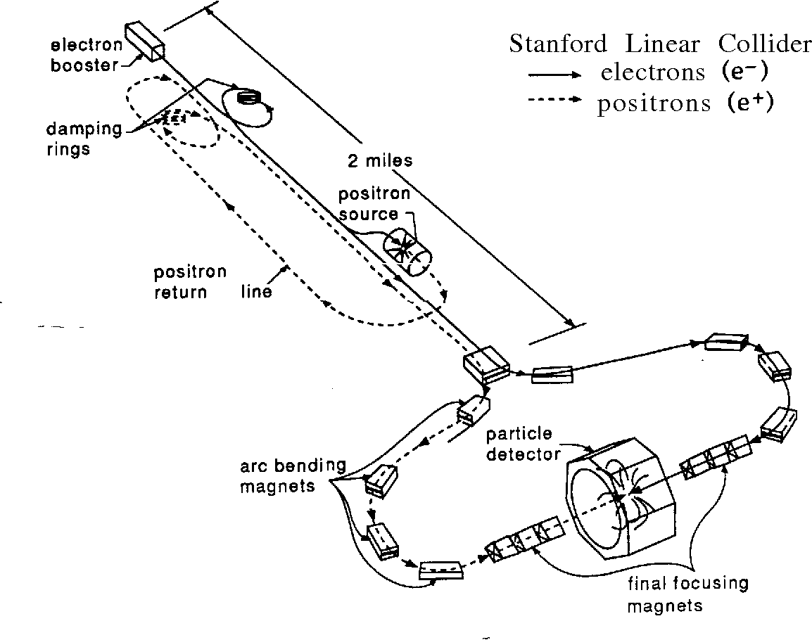

The highest energy lepton colliders ever built were the Stanford Linear Collider (SLC) Phinney (2000), running on the pole at a c.m.e. of 91 GeV, and the Large Electron-Positron (LEP) Collider at CERN Assmann et al. (2002b), the c.m.e. of which was steadily increased from the pole over the threshold (160 GeV), to a highest energy of 209 GeV in a search for the then still elusive Higgs boson. The SLC complex is shown in Fig. 7; the LEP tunnel, including later additions for the LHC, is shown in Fig. 8.
The LEP and SLC operated simultaneously in the 1990s and were rivals in tests of the Standard Model of electroweak physics. In the seven years that LEP operated below 100 GeV, it produced around 17 million particles (and later, at 160 GeV, some 40,000 pairs) collected over four experiments. Accurate determination of the parameters of resonance at 91 GeV led to a rather precise measurement of the number of light neutrino families Schael et al. (2006), a value that, in 2019, could still further be improved to Janot and Jadach (2020), and to an indirect determination of the mass of the top-quark as GeV. Beam energy calibration with the resonant depolarization method was good to about 0.001% and the combined error of the resonance scans of 1.9 MeV on and of 1.2 MeV on were obtained after identifying and correcting for various small, subtle effects, including magnetic field drifts, earth tides, and ground currents induced by a nearby railway Assmann et al. (1999); Brandt et al. (2000). The LEP magnets contained very little steel so as to provide a relatively small bending field of 1.1 kG needed to circulate 100 GeV particles in a 27 km ring. At the highest energy of operation (beam energy of 104.5 GeV), the synchrotron radiation loss per turn was some 3% of beam energy. That explains the need for LEP’s powerful SRF system based on 352 MHz SC niobium-on-copper cavities, which in the last years of operation provided a total RF voltage of about 3.5 GV — see Section II.1.1 for further details. Without collisions, at top energy the LEP beam lifetime was limited by the scattering of beam particles off thermal photons (black-body radiation inside the beam pipe) Telnov (1987), a new effect observed for the first time Dehning et al. (1990). The TMCI Kohaupt (1980); Besnier et al. (1984) limited single bunch current at an injection energy of 20 GeV (later 22 GeV) to about 1 mA. A feedback system to address the TMCI was proposed and attempted Danilov and Perevedentsev (1997). In collision, the luminosity was limited by beam-beam effects at a record high value for the beam-beam tune shift, namely per collision point Assmann and Cornelis (2000), or for the total tune spread.
The SLC — see Fig. 7 — was the world’s first linear collider of single electron and positron bunches. It operated at 120 Hz rate and provided 80% longitudinal polarization at the IP coming from a strained GaAs photo-gun Alley et al. (1995). Other accelerator advances at the SLC included the application of BNS damping Balakin et al. (1983) to suppress the single-bunch beam break up Chao et al. (1980) (a kind of head-tail instability occurring in linear accelerators) and the corresponding emittance growth Seeman (1992), a pulse-by-pulse IP position feedback system, implementation of sophisticated nonlinear optics knobs, procedures for the frequent tuning of various IP optics aberrations Emma et al. (1997); Hendrickson et al. (1999), and a high-efficiency positron source Clendenin et al. (1988), providing more than per s for injection into the SLC linac Krejcik et al. (1992). The SLC also pioneered the beam-beam deflection scans for IP beam-size diagnostics Bambade et al. (1989) and, for the first time, observed beamstrahlung Bonvicini et al. (1989), i.e., the synchrotron radiation emitted during the collision in the electromagnetic field of the opposing bunch, and exploited it for diagnostics purposes. The SLC also demonstrated a significant increase of luminosity, by more than a factor of two, due to “disruption enhancement,” i.e., the mutual focusing of the colliding electron and positron bunches at the interaction point Barklow et al. (1999). During the decade of its operation, from 1989 to 1998, the SLC produced close to 600,000 bosons – about 3% of LEP production – but with a longitudinally polarized electron beam, allowing the SLC’s experiment SLD to perform the world’s single most precise measurement of the weak mixing angle Abe et al. (2000).
Two particle factories that aimed for precision measurements with luminosities far exceeding those of its predecessors (in particular CESR) operated during the first decade of the 21st century. These were the two -factories, PEP-II at SLAC PEP-II Collaboration (1993) and KEKB at KEK tog (1995). They were conceived as asymmetric (unequal energy) two-ring electron-positron colliders, constructed to measure the properties of the quark sector, the violation and to confirm the CKM matrix Bevan et al. (2014). The energy of positrons was much lower than that of electrons, so that the created and mesons had significant forward momentum away from the collision point, making it easier for detectors to pinpoint the origin of the particles’ decay products. Table 2 presents the beam parameters achieved at these colliders. After a few years of operation, both PEP-II and KEKB introduced a so-called top-up injection mode of operation Seeman (2015); Satoh (2010), where small amounts of beam are injected quasi-continually, so as to keep the beam current and luminosity constant over long periods of time, e.g., a day, until the occurrence of a technical failure. The particle detectors remained active and continued data collection during, or shortly after, each beam injection. PEP-II and KEKB had sophisticated transverse and longitudinal bunch-by-bunch feedback systems to suppress coherent instabilities and other measures to allow storage of very high currents Seeman (2008a); Oide (2009). PEP-II holds the world record of stored positrons (at 3.2 A) and electrons (at 2.1 A). KEKB set the world record for highest luminosity at 2.11034 cm-2s-1. KEKB was also the first collider to use SRF crab cavities Oide and Yokoya (1989) to tilt the bunches at the IP and avoid the geometric luminosity reduction due to the crossing angle , Eq. (23) — see Fig. 9. Luminosity improved by a modest 10–20%; the vertical beam-beam parameter increased from 0.06 to 0.09, less than what had been expected from simulations (0.15) Oide (2014); Y.Funakoshi (2014). One possible explanation for the discrepancy is residual nonlinear optics aberrations at the collision point Y.Funakoshi (2014).

II.3 Past advances of hadron colliders
The Intersecting Storage Rings (ISR) at CERN Johnsen (1973) was the world’s first collider. It was made up of two independent, interleaved normalconducting synchrotron rings intersecting at eight points, five of which were used for experiments. The ISR physics program aimed at achieving an understanding of proton structure at the c.m.e. levels, exceeding the most powerful fixed target machines of the SPS at CERN and the Main Ring at Fermilab Giacomelli and Jacob (1979), both of which were constructed after the start of ISR operation. The machine relied on a process called momentum stacking to accumulate record high currents (up to 60 A) and achieved luminosities in hadron collisions surpassed only two decades later Myers (2010). The discovery of Schottky noise resulting from the discrete nature of particles in the beam led to its extensive use for diagnostics of unbunched (coasting or DC) beams and allowed the first successful demonstration of stochastic cooling and reduction of beam emittances van der Meer (1972); Bramham et al. (1975).
SS, the next collider at CERN, was built as a modification of the Super Proton Synchrotron (SPS), with the goal of discovery of the massive neutral intermediate vector bosons Rubbia et al. (1977), successfully achieved in 1983 (1984 Nobel Prize in Physics, Carlo Rubbia) Rubbia (1985). Most critical for the success of the SS was the stochastic cooling of antiprotons (1984 Nobel Prize in Physics, Simon van der Meer), which took place in a specially constructed 3.5 GeV Antiproton Accumulator ring and allowed accumulation of up to 61010 per hour Van Der Meer (1985).
The first superconducting synchrotron in history, the Tevatron Edwards (1985) was also converted into a collider in 1985 Dugan (1989). It was the highest energy collider for 25 years and its legacy includes many results for which the high energy of =1.96 TeV was decisive, such as the discovery of the top quark in 1995, and precise measurements of the masses of the top quark and W boson Quigg (2011b). It was also a pioneering instrument that advanced the frontiers of accelerator science and technology Holmes and Shiltsev (2013); Lebedev and Shiltsev (2014). Its 4.5 T dipole magnets employed Nb-Ti superconducting cable operating at 4.5 K Tollestrup and Todesco (2008), requiring what was then the world’s largest cryogenic system Fowler (1990); Norris and Theilacker (1989). The antiproton production complex Church and Marriner (1993) consisted of three 8 GeV accelerators (the Accumulator, Debuncher, and Recycler — see Fig. 10), and employed 25 independent stochastic cooling systems and one high-energy electron cooling set-up Nagaitsev et al. (2006) to accumulate up to a record high value of 251010 per hour. Over the years, some 1016 antiprotons were produced and accumulated at Fermilab (about 17 nanograms), more than 90% of the world’s total man-made production of nuclear antimatter Shiltsev (2012b). Despite severe parasitic long-range interactions of the two beams, each consisting of 36 bunches placed on helical orbits by two dozen 150 kV high-voltage (HV) separators, a total beam-beam tuneshift parameter of 0.025-0.03 was achieved, a record for hadron beams Shiltsev et al. (2005). Other notable advances included the first high energy accelerator built with permanent magnets — the 3.3 km 8 GeV Recycler Jackson (1996), advanced longitudinal beam manipulation techniques of slip-stacking and momentum mining Koba and Steimel (2002); Bhat (2004), and the first operational use of electron lenses Shiltsev et al. (2008); Shiltsev (2016) for beam collimation Zhang et al. (2008); Stancari et al. (2011) and for compensation of long-range beam-beam effects Shiltsev et al. (1999, 2007). The Tevatron ultimately achieved luminosities a factor of 430 higher than the original design specification.
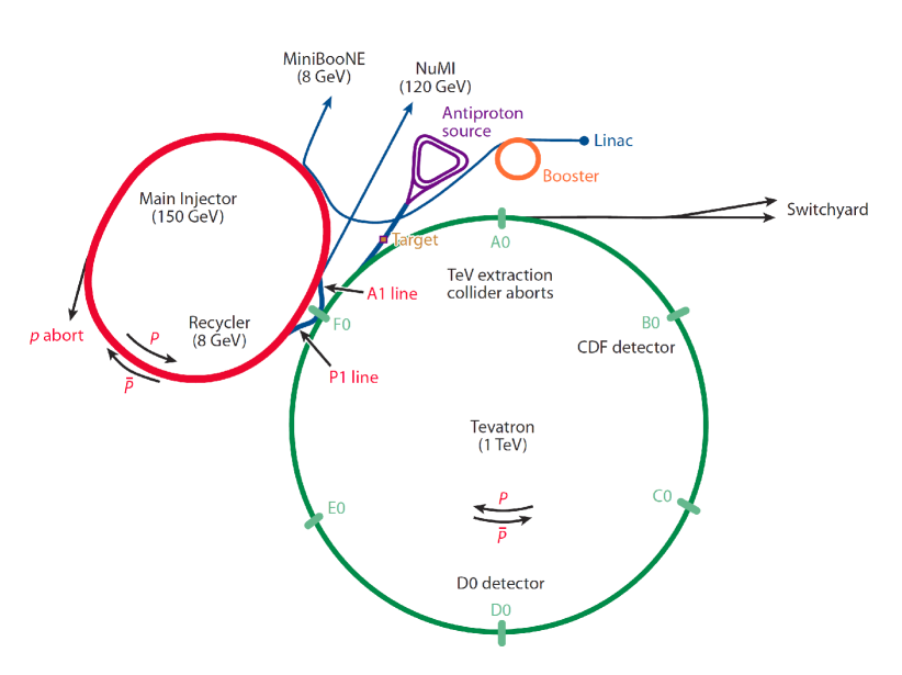
II.4 Past advances of lepton-hadron colliders
The first lepton-proton collider, the 6.4 km long Hadron-Elektron-Ring-Anlage (HERA) at DESY in Germany Voss and Wiik (1994), was the first facility to employ both applications of superconductivity: 5 T magnets in the 920 GeV proton ring and SRF accelerating structures to provide about 12 MW of RF power to compensate for synchrotron radiation losses of 30 GeV lepton beams (positrons or electrons). With proper orbit and optics control, the HERA lepton beam would naturally become transversely polarized to about 60% (within about 40 minutes) thanks to the Sokolov-Ternov effect Barber et al. (1994). Special magnets called spin rotators were implemented on either side of the collider IPs to produce 30–45% longitudinal polarization at the experiments Buon and Steffen (1986); Barber et al. (1995). HERA operated from 1992 to 2005 at of about 320 GeV and luminosities of up to 3–5 cm-2s-1 Willeke (2006), and allowed the investigation of deep-inelastic and photoproduction processes at then highest energy scales Klein and Yoshida (2008).
III Modern colliders
Naturally, the colliding beam facilities of the present utilize many of the advances of past machines in order to operate at the energy or luminosity frontier, or at both. The challenges they face are quite unique and formidable.
III.1 Modern colliders
III.1.1 VEPP-4M and BEPC-II
Two of the currently operational lepton colliders — VEPP-4M in Novosibirsk and BEPC-II at IHEP (Beijing, China) — were originally constructed in the 1980s Xu (1983); Blinov (1983), but went through a long series of optimizations and upgrades, continually contributing important research in modern particle physics. The BEPC (Beijing Electron Positron Collider) was originally built as a single ring collider to produce tau and charm particle physics, but it was later upgraded to a double-ring high-luminosity factory, with up to 2.1 GeV per beam and some 90 bunches. The RF system comprises two SC single cavities at 500 MHz. Longitudinal instability in 1A beams originating from high order modes in the cavities initially limited the luminosity, though this problem was recently resolved through a bunch-by-bunch longitudinal feedback system. The machine reached a record luminosity of 1033cm-2s-1 Qin et al. (2012) at the resonance with GeV Chao and Wang (2008). As of early 2019, the BESIII experiment at BEPC-II finished accumulating a sample of 10 billion events - the world’s largest dataset produced directly from annihilations bes (2019).
The latest of several upgrades of the single ring VEPP-4M collider operating in a wide beam energy range of 0.92–5.2 GeV is a new injection complex Emanov et al. (2018) that now comprises a 270 MeV linac, a 510 MeV linac, injection channels, and a damping ring; this is followed by the 350 MeV to 2 GeV booster-accumulator VEPP-3 ring (which by itself was a collider for a short time in the mid 1970s Gaiduk and Pestov (1976)). Single bunch currents were originally limited at about 7 mA by beam-induced wakefields in the vacuum chambers, but commissioning of the transverse feedback system allowed a many-fold increase to about 25 mA Blinov et al. (2014). Eight pairs of electrostatic separation plates allow operation of bunches in the pretzel orbit scheme. Unique to VEPP-4M is its ability to operate over a wide range of energies and precise determination of beam energy using the resonant depolarization method, with a record high absolute accuracy of 10-6. The former is used in studies of two-photon processes such as , while the latter allows measurements of the masses of the , , and mesons, and the tau lepton with record accuracy Aulchenko et al. (2003); Shamov et al. (2009); Anashin et al. (2010).
III.1.2 VEPP-2000
Significant innovations in beam physics led to the latest of the Novosibirsk colliders, VEPP-2000 which consists of a single ring, with two detectors and two-fold symmetry Shatunov et al. (2000). The VEPP-2000 physics program in the range =0.3 – 2 GeV includes precise measurements of the total hadronic cross section, exclusive hadronic channels, two photon physics, tests of higher order quantum electrodynamics processes, and studies of nucleon form factors at the threshold of the reaction Shemyakin et al. (2016); Achasov et al. (2017). As in other beam-beam limited machines, the VEPP2000 luminosity for a fixed machine lattice scales as . The collider design exploits the round beam concept Danilov et al. (1996) that provides additional stability to particle dynamics, even in the presence of non-linear beam-beam forces via conservation of angular momentum . This scheme requires equal emittances , equal fractional tunes , equal amplitude functions at the IPs , and no betatron coupling in the collider arcs. This scheme was implemented in VEPP2000 by placing two pairs of 13 T superconducting final focusing solenoids into two interaction regions symmetrically with respect to the IPs Shatunov et al. (2016). Observations showed that an extremely high beam-beam parameter =0.25 (similar to LEP in the presence of strong radiation damping) was achieved and that round beams led to significant luminosity enhancement Berkaev et al. (2012); Shatunov et al. (2018).
III.1.3 DANE
DANE at Frascati Vignola (1996) was built in the late 1990s to operate at the energy of the -resonance (1.02 GeV c.m.e.), which with high probability decays to , enabling precision measurements of -meson physics Ambrosino et al. (2006); Bazzi et al. (2011). In 2008, a new collision crab-waist scheme proved to be effective for decreasing without shortening the bunch length, while also reducing the strength of beam-beam resonances at DANE, tripling collider luminosity Zobov et al. (2010); M. Zobov for DAFNE Team (2016). The crab-waist collision combines a large Piwinski angle — see Eq. (23) — with the cancellation of the resulting synchro-betatron resonances which occur under conditions of , where and are integers Piwinski (1986) by means of electromagnetic sextupoles with a special betatron phase advances to the collision point Raimondi (2006); Raimondi et al. (2007). The crab waist collision scheme had first been proposed in 2006 for the former Italian SuperB project Raimondi (2006). Its key concepts and resulting merits Zobov (2013), can be understood from Fig. 11, which presents two bunches colliding under a horizontal crossing angle . The first ingredient is a large Piwinski angle , as it had earlier been proposed for hadron colliders Ruggiero and Zimmermann (2002). In the crab-waist scheme, is increased by decreasing and increasing . In this way, the luminosity increases and the horizontal tune shift decreases; the effect of any parasitic collisions around the primary collision point becomes negligible. However, the most important effect is that the overlap area of the colliding bunches is reduced, since it is proportional to (see Fig. 11).
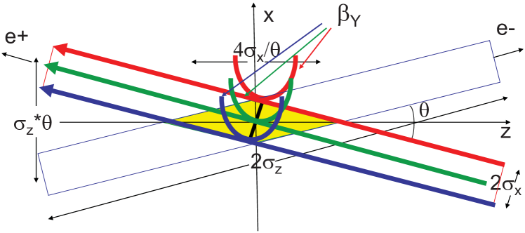
a) Crab sextupoles OFF
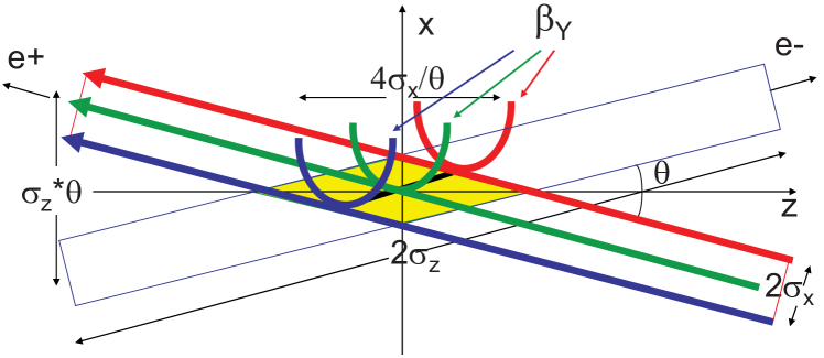
b) Crab sextupoles ON
As a second ingredient, the vertical -function is made comparable to the overlap area size (i.e. ):
| (29) |
Reducing at the IP yields a luminosity increase at the same bunch current. In addition, if the bunch current is limited by — which decreases when is lowered — the bunch current can be raised to further push up the luminosity. The vertical synchrobetatron resonances are also suppressed Pestrikov (1993). With a finite overlap region, decreasing does not require an associated decrease in the bunch length, as would be required in the standard collision scheme because of the hourglass effect. The possibility of a longer bunch length also improves local higher-order-mode heating and any effects of coherent synchrotron radiation. However, implementation of the above two ingredients excites new beam-beam resonances, which may strongly limit maximum achievable tune shifts. For this reason, the crab-waist transformation was introduced Zobov et al. (2010); M. Zobov for DAFNE Team (2016), as a final and third ingredient. As seen in Fig. 11 (bottom), the -function waist of one beam is now oriented along the central trajectory of the other beam. In practice, the rotation of the vertical -function is accomplished by sextupoles placed on both sides of the IP in phase with the IP (modulo ) horizontally and at betatron phase difference (modulo ) vertically. The integrated strength of these sextupoles should satisfy the following condition, which depends on the crossing angle and on the -functions at the IP (superindex ∗) and sextupole locations (subindex “sx”),
| (30) |
where is the particle (electron) charge and the design momentum. The main effect of the crab waist transformation is the suppression of betatron and synchrobetatron resonances arising (in collisions without crab waist) due to vertical tune modulation by horizontal betatron oscillations. The collision of flat beams with is an essential condition for resonance suppression with the crab sextupoles Shatilov et al. (2011). The implementation of crab-waist collisions at DANE provided an increase in luminosity by a factor of 3, in good agreement with numerical simulations Zobov et al. (2009); Shatilov et al. (2011). All ongoing or proposed projects for next-generation circular lepton factories are based on the crab-waist scheme: SuperKEKB, the Super -charm factories SCT Piminov (2018) and HIEPA Luo et al. (2019), finally yet importantly the Higgs and electroweak factories FCC-ee Benedikt et al. (2019a); Bogomyagkov et al. (2014a); Oide et al. (2016), and CEPC CEPC Study Group (2018).
III.1.4 SuperKEKB
The SuperKEKB at KEK is an collider with a design peak luminosity of 81035cm-2s-1 Ohnishi et al. (2013) (40 times that of the KEKB B-factory, see above) at close to the mass of the resonance making it a second-generation B-factory for the Belle II experiment Abe et al. (2010). SuperKEKB is an asymmetric-energy and double-ring collider with a 7 GeV electron ring and a 4-GeV positron ring; see Fig. 12. Its mission is to seek new physics beyond the Standard Model with a target integrated luminosity of 50 ab-1. Referring to Eq. (28), the luminosity gain of 40 with respect to its predecessor KEKB is achieved with the same beam-beam parameter , twice as high a beam current , an order of magnitude smaller transverse emittances, and a vertical IP beta function 20 times smaller than that of KEKB, namely =0.3 mm. The latter realizes the nanobeam scheme, named such because the vertical beam sizes at the IP can be squeezed to 50 nm. The SuperKEKB nanobeam scheme is an adaptation of the original 2006/2007 crab-waist proposal for the Italian SuperB project Raimondi et al. (2007) to SuperKEKB. The scheme involves a large horizontal crossing angle between two colliding beams mrad, such that the Piwinski angle is very large , with a bunch length much longer than the beta function at the IP mm and small horizontal and vertical emittances. Unlike a head-on collision scheme, here the bunches intersect one another only at the short and narrow central parts close to the IP. The first collisions in SuperKEKB occurred in April 2018, eight years after the end of the KEKB operation, and successful collider commissioning is underway Ohnishi (2018); Akai et al. (2018). For the year 2020, SuperKEKB operation is planned with crab-waist collisions (see Ch. III.1.3) at values in the mm range.
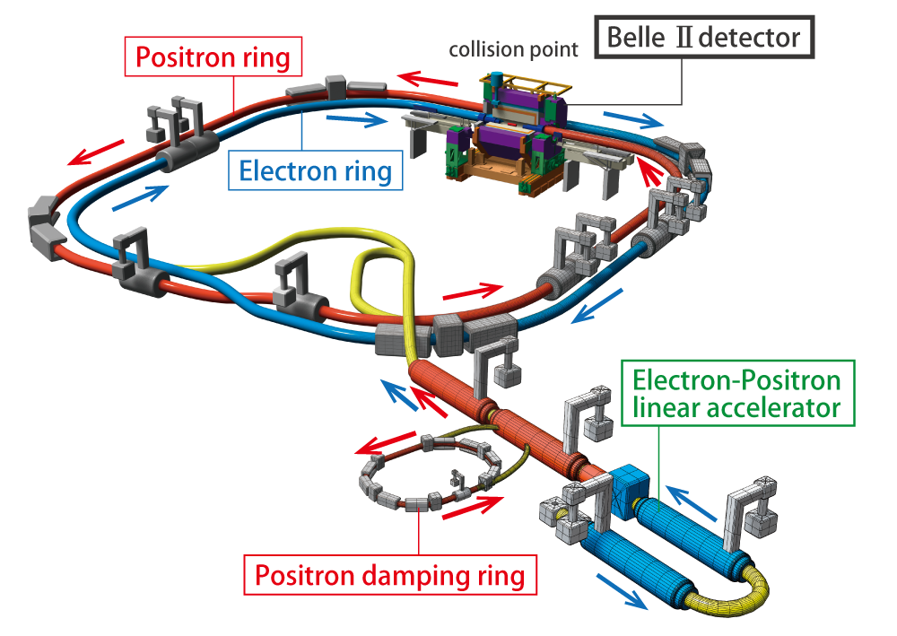
Table 2 compares the achieved parameters of PEP-II and KEKB, with the design values of SuperKEKB Akai et al. (2018).
| Parameter | Unit | PEP-II | KEKB | SuperKEKB | |||
|---|---|---|---|---|---|---|---|
| (achieved) | (achieved) | (design) | |||||
| ring | LER | HER | LER | HER | LER | HER | |
| Species | |||||||
| Beam Energy | GeV | 3.1 | 9.0 | 3.5 | 8 | 4 | 7 |
| Circumference | m | 2199 | 3016 | 3016 | |||
| Horizontal IP beta function | mm | 1050 | 400 | 1200 | 1200 | 32 | 25 |
| Vertical IP beta function | mm | 9–10 | 9–10 | 5.9 | 5.9 | 0.27 | 0.30 |
| Hor. rms norm. emittance | m | 182 | 880 | 123 | 376 | 25 | 63 |
| Vert. rms norm. emittance | m | 4.8 | 14 | 1 | 3.4 | 0.07 | 0.3 |
| Beam current | mA | 3213 | 2069 | 1640 | 1190 | 3600 | 2600 |
| Bunches / beam | 1658 | 1584 | 2500 | ||||
| Bunch current | mA | 1.94 | 1.25 | 1.04 | 0.75 | 1.44 | 1.04 |
| Rms bunch length | mm | 10–12 | 10–12 | 7 | 7 | 6.0 | 5.0 |
| Full Crossing Angle | mrad | 0 (crab crossing) | 83 | ||||
| Vert. beam-beam parameter | 0.047 | 0.062 | 0.098 | 0.059 | 0.069 | 0.060 | |
| Luminosity | cm-2s-1 | 1.2 | 2.11 | 80 | |||
III.2 Modern hadron colliders
Two hadron colliders are presently in operation — the Relativistic Heavy Ion Collider (RHIC) at Brookhaven National Laboratory (BNL) and the Large Hadron Collider (LHC) at the European Organization for Nuclear Research (CERN). Both collide either protons (polarized protons in the case of the RHIC) or other, heavier ions, or protons with ions. For the LHC, a high-luminosity upgrade (HL-LHC) has been approved and will come into operation around 2026. Typical parameters of the RHIC and LHC, and design parameters for the HL-LHC are compiled in Table 3.
| Parameter | RHIC | LHC | HL-LHC | |||
| (2018) | (design) | |||||
| Species | ||||||
| Max. beam energy (TeV) | 0.255 | 0.1/n | 6.5 | 2.72/n | 7 | 2.76/n |
| Circumference (km) | 3.834 | 26.659 | 26.659 | |||
| Polarization | 55% | n/a | n/a | n/a | n/a | n/a |
| Beta function at IP (m) | 0.65 | 0.7 | 0.300.25 | 0.5 | 0.15 | 0.5 |
| Transverse emittance (m, rms, norm.) | 3 | 2.2 | 1.9 | 2.3 | 2.5 | 1.7 |
| IP beam size (m) | 85 | 115 | 8 | 19 | 7 | 17 |
| Beam current (mA) | 257 | 220 | 550 | 24 | 1100 | 33 |
| Bunches per beam | 111 | 111 | 2556 | 733 | 2760 | 1232 |
| Bunch population () | 18.5 | 0.2 | 1012.5 | 0.02 | 22 | 0.02 |
| Bunch length (rms, cm) | 60 | 30 | 8 | 710 | 9 | 8 |
| Full crossing angle (rad) | 0 | 0 | 320–260 | 300 | 500 | |
| Beam-beam parameter / IP, () | 7.3 | 4.1 | 4.5 | 1.1 | 8.6 | 1.1 |
| Luminosity ( cm-2s-1) | 245 (peak) | 0.016 (peak) | 0.007 | 0.006 | ||
| 150 (avg.) | 0.009 (avg.) | (leveled) | (leveled) | |||
| Max. int’d NN lum./experiment (fb-1) | 1.3 at 250/255 | 0.03 | 169 | 0.04 | 250 / y | 0.43 |
III.2.1 RHIC
The RHIC is a double ring which collides heavy ions and/or polarized protons circulating in opposite directions. It is based on SC Nb-Ti dipole magnets with a field of 3.45 T and housed in the 3.84 km tunnel previously built for the abandoned ISABELLE project. The two RHIC rings cross at six IPs. Two large experiments, STAR and PHENIX, are located at the interaction points referred to as six and eigth o’clock, respectively — see Fig. 13. The PHENIX experiment is presently undergoing a major upgrade to become sPHENIX.
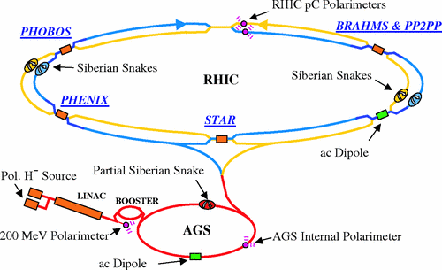
The RHIC brings into collision combinations of fully-stripped ions such as H-H (p-p), p-Al, p-Au, d-Au, h-Au, Cu-Cu, Cu-Au, Au-Au, and U-U over a wide energy range. The high charge per particle (+79 for gold, for instance) makes IBS of particles within the bunch a special concern, even for moderate bunch intensities.
3D stochastic cooling of bunched ion beams was successfully implemented in the RHIC in 2012 Blaskiewicz et al. (2010) and is now routinely used. With stochastic cooling, steady increases in bunch intensity, and numerous other upgrades, the RHIC now operates with average luminosity in Au-Au collisions of cm-2s-1 which is 44 times the design value. Another special feature of accelerating heavy ions in the RHIC is that the beams cross the “transition energy” during acceleration — a point at which and the derivative of the revolution period with respect to the momentum is zero, leading to zero synchrotron tune and temporary formation of very short and potentially unstable bunches according to Eqs. (18, 19, 20). This is quite typical for low-energy accelerators, where the necessary phase jump required of the RF system is implemented rapidly and little time is spent near this condition. In the case of RHIC accelerating heavy ions, SC magnets cannot ramp very quickly and the period of time spent crossing transition is relatively long and must be dealt with carefully. For operation the beams are always above their transition energy and so this condition is completely avoided.
The RHIC physics program greatly relies on the machine’s ability to accelerate and collide polarized proton beams Bunce et al. (2000). Proton beam polarization is produced in a low-energy source Zelenski (2010) and must be maintained through numerous depolarizing resonances during the acceleration cycle Bai et al. (2006). A proton beam energy of 255 GeV with 55% final polarization per beam has been realized Roser (2008); Ranjbar et al. (2017). As part of a scheme to compensate for the head-on beam-beam effect, two electron lenses were installed; in 2015, these operated routinely during polarized proton operation at 100 GeV beam energy and doubled both peak and average collider luminosity Fischer et al. (2015); Gu et al. (2017).
RHIC physics searches for a critical point in the nuclear matter phase diagram Stephans (2006) required operation below the nominal injection energy of 10 GeV/u. In order to reach the integrated luminosity goals, the first bunched beam electron cooler, with electrons from a high-current high-brightness RF accelerator Kayran et al. (2020), was successfully commissioned for the lowest RHIC energies Kayran et al. (2019).
III.2.2 LHC
The superconducting Large Hadron Collider is the world’s highest energy collider Evans and Bryant (2008); Bruning et al. (2012). It supports a broad particle-physics program at the energy frontier Gianotti et al. (2005).
Over most of the LHC’s 26.7 km circumference, the two counter-rotating hadron beams are contained in two separate vacuum pipes passing through the same superconducting twin-aperture Nb-Ti accelerator magnets. The LHC beams cross at four IPs, which host two multipurpose high-luminosity experiments, ATLAS and CMS, and two special purpose experiments, ALICE (mainly devoted to heavy-ion physics) and LHCb (B meson physics). With four crossings, as shown in Fig. 14, each beam passes half of a revolution on the outer side, the other half on the inner, so that the circumferences of the two beams are identical. Construction of the LHC technical components and their subsequent installation took more than a decade (1995–2007), and the machine’s cost to CERN’s budget was 3756 MCHF plus 1224 MCHF of labor cost Evans (2009); colliding beam operation started in 2010. Operation of the LHC machine requires some 120 MW of AC wall plug power that is about half of 230 MW for the entire CERN, whose annual electric energy consumption is about 1.3 TWh (2015) CERN FAQ ”LHC: The Guide” () (2017).
Table 3 shows the LHC luminosity performance in and collisions. In collisions the LHC has so far reached a world record luminosity of cm-2s-1, which, within the measurement accuracy, equals the record for colliders still held by KEKB. For the LHC’s ATLAS and CMS experiments, in the first ten years of the LHC operation, the luminosity well exceeded the design value of cm-2s-1, while for the ALICE experiment the luminosity needed to be “levelled” around this value Jowett (2018). The LHC can also provide collisions as it did in 2013 and 2016, and other ion-ion or ion-proton collisions, at different energies.
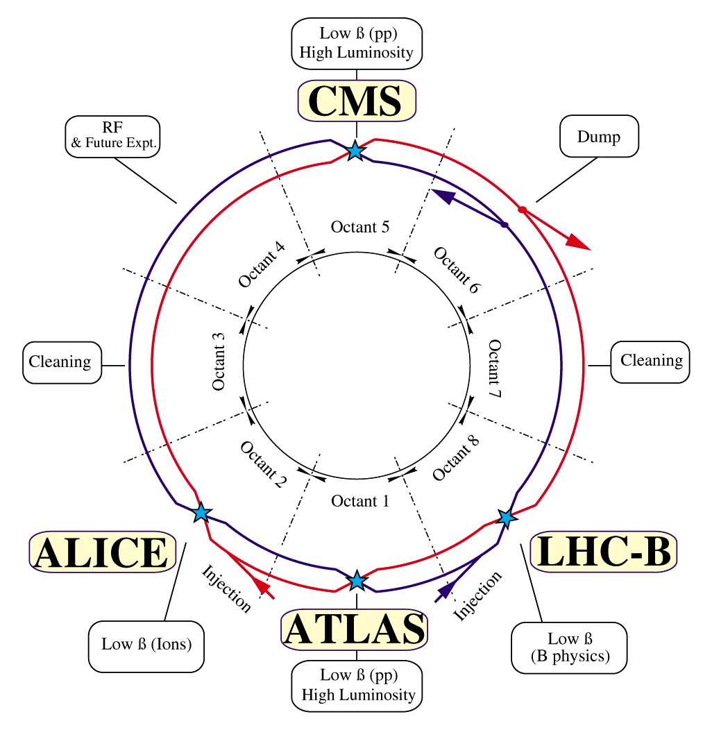
In the LHC Run 2 (from 2015 through 2018), operation for HEP was conducted with 6.5 TeV protons in each beam. The LHC has set many records for both peak and annual integrated luminosities of hadron colliders (see Fig. 15), largely surpassing the total integrated luminosity of all previous hadron colliders combined. It is predicted that the final-focusing quadrupoles around the ATLAS and CMS experiments will be destroyed by radiation from collision debris after a total integrated luminosity of around 300 fb-1. More than half of this value has already been delivered. This provides motivation and guides timing for the High Luminosity LHC (HL-LHC) upgrade Apollinari et al. (2017), scheduled for around 2025, when the final quadrupole triplets will be exchanged with new ones of larger aperture.

Initial luminosity measurements were conducted by sweeping beams transversely across each other (so-called van der Meer scan Balagura (2011)) as was done long ago on the ISR van der Meer (1968). Both total and inelastic cross sections for collisions were measured with high precision in the first years of LHC operation, e.g. Antchev et al. (2019). These are important for beam lifetime and for event pile-up (the number of interactions per bunch crossing) in the detectors. Notably, the LHC beam energy is known to 0.1% and the orbit circumference slowly varies due to Earth tides by some 1.1 mm Todesco and Wenninger (2017).
The extremely high luminosities at the LHC, of up to cm-2s-1, Steerenberg et al. (2019) are achieved by (1) operating high-quality beams from the injector complex, presently comprising a 50 MeV proton linac (to be replaced, in 2020, by a 160 MeV H- linac), 1.4 GeV PS Booster (being upgraded to 2 GeV), the 26 GeV Proton Synchrotron (PS), and the 450 GeV Super Proton Synchrotron (SPS), with transverse emittances that are more than lower than the design; (2) smaller , which got decreased from the design value of 55 cm down to 25 cm in 2018, also thanks to the lower emittance allowing to avoid the aperture limitation in the final focus quadrupoles where the maximum beta-function grows according to Eq.(15); and (3) by a large number of bunches and a high beam current 0.5 A. An outstanding optics control and excellent optics reproducibility at the LHC Tomás et al. (2012); Persson et al. (2017b); Maclean et al. (2019) enabled achieving the aforementioned low value of with excellent beam-beam performance, and while guaranteeing the safety of the machine.
In the LHC at energies of 5–7 TeV per proton, for the first time synchrotron radiation transforms from a curiosity to a challenge in a hadron accelerator. At design beam current, the system must remove roughly 7 kW due to synchrotron radiation. As photons are emitted, their interactions with the vacuum chamber wall can generate free electrons, with consequent electron cloud development Dominguez et al. (2013). The heat load due to synchrotron radiation, electron cloud, and also beam image currents, is intercepted by a special “beamscreen” installed inside the magnets. The beamscreen temperature of 5–20 K is higher than the 1.9 K of the cold bore, which allows for efficient heat removal and for cryopumping through numerous slots in the screen’s top and bottom. Overall, the LHC vacuum system comprises 150 cubic meters of beam vacuum and 9000 cubic meters of cryogenic vacuum; the LHC beam lifetime due to interaction with residual vacuum molecules is larger than 100 hrs Cid-Vidal and Cid (2011).
The LHC beam currents translate into stored energies of several hundreds of MJ per beam. Component protection, beam collimation, and controlled energy deposition are consequently of high priority Valentino et al. (2012). Of particular concern is the possible failure mode of an asynchronous beam dump, where a single extraction kicker module accidentally fires. This would trigger the firing of all other kickers (with some delay), but some bunches will be swept across the aperture. These errant bunches would be intercepted on primary collimators, made of robust carbon-fibre-reinforced carbon to withstand such a catastrophic scenario. The LHC collimation system consists of more than 100 collimators, organized hierarchically. The measured cleaning performance, beam loss rates, and loss distributions have been consistent with expectations, even during the delicate phase of the squeeze Tygier et al. (2019). Beam particles scattered off the short primary collimators (TCPs) are caught by longer secondary collimators (TCLs) placed at slightly larger apertures, with appropriate phase advances behind the primaries. Tertiary collimators (TCTs) are placed in front of the final quadrupole triplets around the collision points. Special collimators protect against errors at injection sites and, especially, at the entrance of the beam extraction channel. Still other collimators catch large amplitude debris particles coming from the collision point. The system is designed such as to keep any beam loss in cold magnets to a minimum, and to ensure no magnet quenches even for a proton beam lifetime as low as 12 minutes.
At the LHC, where the two beams are brought together into a single common beam pipe at each of the four IPs, the large number of bunches, and subsequent short bunch spacing (25 ns), would lead to approximately 30 head-on collisions through 120 m of common beam pipe at each IP. A small crossing angle is thus employed, which reduces the luminosity by about 15%, with a similar reduction in the total beam-beam tune shift Ruggiero and Zimmermann (2002). Still, in the common beam-pipe section around each IP, the bunches moving in one direction will experience about 30 parasitic long-range encounters with counter-rotating bunches. At the LHC, the beams are crossed alternatingly in the horizontal and vertical planes, so that to first order the tune shift induced by the long-range collision cancels between the IPs Neuffer and Peggs (1986). For the HL-LHC, it is considered to compensate for residual perturbations of particle motion due to long-range parasitic collisions, e.g., with the help of current-fed wire compensators Papaphilippou and Zimmermann (1999). In that scheme, 1 m long thin current-carrying wires will be placed parallel to both beams at a normalized distance not much larger than the beam-beam separation at long-range collision points and, therefore, will provide similar but opposite action Koutchouk (2001); Dorda (2008). Prototype wire compensation tests at the LHC have been successful Sterbini et al. (2019).
As had been predicted Zimmermann (1997); Baglin et al. (1998); Furman (1998); Rumolo et al. (2001), an intensity limit has indeed arisen at the LHC from the build up of an electron cloud inside the vacuum chamber Dominguez et al. (2013). This electron cloud may drive different types of beam instabilities and creates additional significant heat loads on the beam screen inside the cold magnets. Indeed, the electron cloud is a primary source of beam instability in the LHC, especially with a proton bunch spacing of 25 ns. Beam performance tends to improve in time thanks to beam-induced surface conditioning (“scrubbing”). In addition, occasional losses of transverse or longitudinal Landau damping arise due to classical machine impedance with contributions from the resistive vacuum chamber, RF cavities, and chamber transitions. With regard to instability mitigation, the following lessons have been learned in operating the LHC E. Métral et al. (2014, 2017); E. Metral (2016); R. Tomas, in Proc. EuCARD-2 XBEAM Strategy Workshop “From EuCARD-2 XBEAM to ARIES APEC” , p.22; eds. A. Faus-Golfe, G. Franchetti and F. Zimmermann() (Valencia, 13-17 February, 2017): (i) there exists a narrow range of machine settings for which the beam remains stable all along the cycle; (ii) instabilities occur if transverse betatron coupling exceeds a certain threshold value (different at different stages of operation); (iii) chromaticity settings are crucial along the cycle and cannot be relaxed; (iv) second-order chromaticity can contribute to beam stabilization Schenk et al. (2018); (v) octupole-magnet settings have to be adapted according to beam emittance; and (vi) the transverse damper is indispensable to preserve beam stability all along the acceleration cycle.
Interestingly, the electron cloud can drive coherent instabilities even when beams are in collision, with associated strong Landau damping. Simulations and earlier measurements at the SPS show that, for lower bunch intensities, the electron cloud in the dipoles tends to form a central stripe. At the LHC, the central density threshold of the electron-cloud driven single-bunch head-tail instability ( m-3 at a chromaticity of ) is crossed when the bunch intensity decreases; for , the threshold becomes much higher. This explanation of beam instabilities observed towards the end of LHC physics fills is also consistent with the disappearance of the phenomenon after scrubbing.
Heavy-ion luminosity at the LHC can be limited by the so-called bound-free pair production (BFPP) during the collision of nuclei:
| (31) |
This process, with a large cross section of about barn, generates a secondary beam of ions, with a fractional rigidity change equivalent to a relative momentum deviation of , that can potentially quench superconducting magnets downstream of the IP (see Ref. Jowett (2018) and references therein). In 2015, orbit bumps were introduced to displace the BFPP losses safely into a connection cryostat, thereby avoiding magnet quenches Jowett (2018).
In the coming years, the ambitious HL-LHC upgrade program Apollinari et al. (2017) aims at an order-of-magnitude increase in integrated proton-proton luminosity. The heavy-ion physics program of the LHC will also continue during the HL-LHC period, with approximately ten times higher peak luminosities in and collisions than available at the present LHC.
In the HL-LHC, the will be squeezed even further, to as low as 10 cm, with the help of a novel Achromatic Telescopic Squeeze (ATS) optics Fartoukh (2013) (which is presently being tested and commissioned in the LHC), along with new larger aperture Nb3Sn final quadrupoles Rossi and Tommasini (2019) and crab cavities. Additional collimators will be installed inside the dispersion suppressors around the main collimation (cleaning) insertion, and around some of the experiments. The purpose of adding these collimators is to absorb off-energy particles generated during collisions (especially heavy-ion collisions) or by scattering off one of the existing primary or secondary collimators. The new collimator installation requires the replacement of several 8.3 T Nb-Ti dipoles by stronger and shorter 11 T dipoles made from Nb3Sn superconducting cable to provide the necessary space without altering the overall geometry.
According to a recent proposal W. N. Krasny and A. Petrenko (2020), the collision of low-emittance calcium ion beams in the HL-LHC promise partonic luminosities similar to, or higher than, the HL-LHC operation, at a lower event pile up W. N. Krasny and A. Petrenko (2020). The low-emittance beam would be produced by fast transverse laser cooling ( s) of partially stripped calcium ions in the SPS, based on the Gamma Factory concept Krasny (2015); Krasny et al. (2018) (also see Ch. IV.3.2).
IV Future Colliders
Both nuclear physics and particle physics face critical questions which require next-generation colliding-beam facilities. Understanding of protons and neutrons, or nucleons — the building blocks of atomic nuclei — has advanced dramatically, both theoretically and experimentally, over the past half a century. It is known that nucleons are made of fractionally charged valence quarks, as well as dynamically produced quark-antiquark pairs, all bound together by gluons, the carrier of the strong force. A central goal of modern nuclear physics is to understand the structure of the proton and neutron directly from the dynamics of their quarks and gluons governed by the quantum chromodynamics — see more details in, e.g., Ref. of Sciences Engineering and Medicine (2018) and references therein.
For HEP to make significant advances, major new machines of two types will be required. The first type is Higgs factories with a c.m.e. of 240–250 GeV for precision studies of the Higgs boson ( GeV) and exploration of the Higgs sector in greater detail, including measurements of Higgs couplings to fermions and vector bosons, self coupling, rare decays, mass and width. These Higgs factories could also furnish important complementary electroweak precision measurements at other collision energies, e.g., on the pole, above the boson threshold, and at energies sufficient for production. The second type is colliders exploring the energy frontier for potential discoveries through direct searches with c.m.e. levels significantly beyond those of the LHC. The next energy-frontier colliders would aim at producing and discovering new particles/phenomena beyond the Standard Model, reaching mass-scales in the range of tens of TeV and offering a widely extended discovery reach for new gauge bosons and , colorons, diquark scalars, SUSY, heavy Higgs, test for compositeness of the Standard Model particles, etc.
In addition, precision physics at future high-luminosity factories operating at the -charm energy also provides sensitivity to new physics at multi-TeV energies and beyond. Reference Ellis et al. (2019) presents a comprehensive review of the emerging particle physics landscape and its potential future.
Below we comprehensively detail colliders which are believed to be feasible (both technically and cost-wise) for construction over the next several decades. All of these rely mostly on currently available technologies, such as NC or SC RF and/or NC or SC magnets, and generally require either no or limited R&D to assure energy reach and performance.
IV.1 Ion, - and - colliders
IV.1.1 NICA
NICA (Nuclotron-based Ion Collider fAсility) is a new accelerator complex under construction at the Joint Institute for Nuclear Research (JINR, Dubna, Russia) Kekelidze et al. (2012). Its purpose is to study properties of hot and dense baryonic matter, spin physics, properties of the strong interaction vacuum and QCD symmetries, to explore the nature and properties of strong interactions between quarks and gluons, and to search — for signs of the phase transition between hadronic matter and quark-gluon plasma plus new phases of baryonic matter Sissakian et al. (2009); Senger (2016); Brodsky (2016).
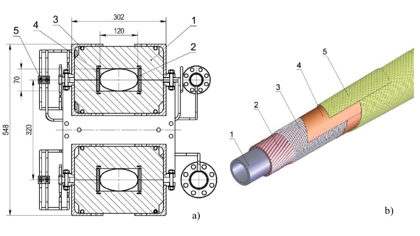
NICA will provide a variety of beam species, ranging from protons and polarized deuterons to massive gold ions. The collider average design luminosity in heavy ion and light ion collisions at =4–11 GeV is =11027cm-2s-1 for a variety of nuclei up to and should be in the range =(1–10)1031cm-2s-1 for polarized proton and deuteron collisions in an energy range of =12–27 GeV. The facility employs some existing injectors such as light ion sources, an Alvarez type linac LU-20 based source of polarized protons and deuterons, a new electron string ion source (ESIS) that will provide up to 2109 gold ions per 7 s pulse at 50 Hz rate, and a linear accelerator consisting of RFQ and RFQ Drift Tube Linac (RFQ DTL) sections. The linac accelerates ions with mass-to-charge ratio 8 up to an energy of 6 MeV/u, with efficiencies higher than 80%. A new 600 MeV/nucleon Booster synchrotron ring with a circumference of 211 m will be housed inside the historical JINR Synchrophasotron yoke. Its maximum magnetic rigidity of 25 Tm is provided by 40 1.8 T SC dipole magnets operating at 4.5 K, which can be ramped at 1.2 T/s Kostromin et al. (2016). The 60 keV electron cooling system of the Booster, needed for ion accumulation and rapid (3–4 sec) reduction of the beam emittance up to 100 MeV/u energies, has been built and commissioned Bubley et al. (2017); Zinovyev et al. (2018). Ions, protons and deuterons are then further accelerated, up to the energy of the collider experiments, using the upgraded Nuclotron synchrotron — a 251.52 m circumference superconducting magnet ring, operational since 1993 Issinsky et al. (1994). This ring has a maximum field of 2 T, ramping rate of 1 T/s for a 4 s cycle, and a maximum magnetic rigidity of 45 Tm. The collider itself will consist of two SC rings of racetrack shape, with maximum magnetic rigidity of 45 Tm and a circumference of 503.04 m. Two IPs are foreseen in opposite straight sections of the NICA collider — one for heavy-ion studies with the multi-purpose detector (MPD) Golovatyuk et al. (2016) and another for polarized beams, housing the spin physics detector (SPD) experiment Savin et al. (2016). The maximum field of the collider dipole superferric magnets, which use iron to shape the field and superconductors to excite it, is 1.8 T Khodzhibagiyan et al. (2019) — see Fig. 16. Intrabeam scattering is predicted to result in short emittance growth times of about 3 min at 1 GeV/u and about 40 min at 4.5 GeV/u — see Table 4. Effective stochastic and electron cooling systems are required to counteract the emittance growth and to assure operation with a high average luminosity. In the energy range of 1 to 3 GeV/u, a 2.5 MeV, 0.5 A electron cooling system should provide a comparatively short 10 s cooling time and will allow operation of the collider at the space-charge limit of about . In the ion beam energy range of 3 GeV/u to 4.5 GeV/u, a stochastic cooling system will ensure characteristic cooling times of about 500 s Kostromin et al. (2012).
IV.1.2 Low energy electron-ion collider proposals: ELISe at FAIR, EicC at HIAF
The electron-ion collider (EIC) experiment ELISe Antonov et al. (2011) is part of the experimental program envisaged at the international Facility for Antiproton and Ion Research (FAIR Gutbrod et al. (2006)) in Darmstadt, Germany. It will offer the unique opportunity to scatter electrons with an energy of up to 0.5 GeV off short-lived exotic nuclei with energies up to 0.74 GeV/nucleon Simon (2007); Suda and Simon (2017), in order to investigate the structure of radioactive isotopes. Figure 17 presents the schematic layout of the New Experimental Storage Ring (NESR, circumference 222.9 m) Dimopoulou et al. (2007) for Rare Isotope Beams (RIB) and the Electron Antiproton Ring (EAR, circumference 53.7 m, selected such that the revolution frequency of the EAR is 5 times that of one of the ions). Electrons with energies ranging from 125 to 500 MeV will be provided by an electron linac and stored in the EAR. Antiprotons of similar momentum can be directed from a dedicated collector ring (not shown in Fig. 17) into the EAR via a separate beam line. The electron ring is placed outside the NESR, so that a bypass beam line connects them and provides sufficient space for the electron spectrometer and a recoil detector system. The ion and electron (or antiproton) beam trajectories intersect at an IP surrounded by an electron spectrometer; auxiliary detectors for measuring reaction products are also included in the ELISe plan.
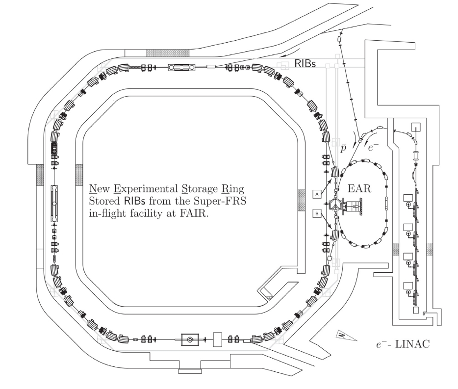
Experiments require high resolution of transferred energy and momentum in electron-ion scattering. A momentum spread of the electron beam (8 bunches, 510 each) of about 0.036% can be achieved; its value mainly depends on intra-beam scattering (IBS) and statistical fluctuations due to synchrotron radiation. IBS also causes the beam size to grow and limits both luminosity and lifetime. Collision focusing optics with 15/100 cm allows for luminosity values ranging from =1028 cm-2s-1 to 1030 cm-2s-1 for a wide variety of isotopes from He to U. The number of ions in each of 4 NESR bunches varies between 7107 and 8109, depending on the optimization of production and preparation of secondary beams, maximum yield, and the acceptance of the Super FRagment Separator (Super-FRS). At high intensities, the ion population is expected to be limited by space-charge effects at a tune shift parameter of — see Table 4.
Construction work on the FAIR project began in the summer of 2017. The final scope of the project, consisting of many rings, and the construction schedule will depend on cost. In 2005, this was estimated to be 1,262 M Euros but was recently reconsidered; additional funding needed amounts to 850 M Euros, not including contingencies Report of the FAIR Progress and Cost Review Board .
Conceptually similar is a proposal Chen (2018a) from the Institute of Modern Physics (IMP CAS, Lanzhou, China) to build a high luminosity polarized electron-ion collider in China (EicC) with =41033cm-2s-1 at 12-24 GeV, based on the capabilities offered by the Heavy Ion High Intensity Accelerator Facility (HIAF Yang et al. (2013)). The Huizhou HIAF project was approved in 2015, with construction commencing in 2018; facility commissioning is expected in 2025. The 2.5 billion Chinese yuan complex will operate a 180 m long superconducting 17 MeV/nucleon linac and a 569 m 34 Tm Booster Ring capable of accumulating, cooling and accelerating ions to 4.25 GeV/nucleon or protons to 9.3 GeV. The first stage of the complex extension to the electron-ion collider calls for an additional high current (3–4 A) 3.5-5 GeV electron ring to collide with up to 20 GeV HIAF protons and ions, an SRF 4–5 pass linac-ring electron injector, a polarized ion source, and Siberian snakes for the existing HIAF accelerators — see Table 4. The final stage of the EicC, called EicC-II, assumes the new construction of 1.5–2 km long, figure-8 shaped 60–100 GeV proton and 5–10 GeV electron rings in the same tunnel Chen (2018b). Construction cost, as well as details of the design and schedule of the Chinese electron-ion collider, require further study.
IV.1.3 High-energy electron-ion collider (EIC) proposals: JLEIC at TJNAF and eRHIC at BNL
Higher energy electron-ion colliders can answer scientific questions which are central to completing our understanding of nuclear matter as well as being integral to the agenda of nuclear physics today. For example, the 2018 National Academies of Science assessment of US-based EIC science of Sciences Engineering and Medicine (2018) emphasized the priority of constructing a new facility that will be flexible over a multi-decade operating lifetime, and which can support exploration of nuclear physics over a wide range of center-of-mass energies and ion species with highly polarized electrons and light ions. According to the White Paper Accardi et al. (2016), the requirements of an EIC include highly polarized (70%) electron and nucleon beams (as the precision of measurements of interest scales as ), a spectrum of ion beams from deuterons to the heaviest nuclei (U or Pb), variable c.m.e. values from 20 GeV to 100 GeV, upgradable to 140 GeV, high luminosities of 1033-34 cm-2s-1, as well as possibilities of having more than one interaction region. Significant accelerator R&D is needed to attain the required energy, luminosity, and polarization, including development of SRF crab-cavities and advanced SC magnets for collider rings and interaction region focusing, ERL based electron cooling of hadron beams, essential to attain luminosities two orders of magnitude beyond the predecessor HERA collider, and polarized particle sources beyond the state-of-the-art, augmented by the development of special magnets and operational techniques to preserve the polarization through the acceleration process to the collisions.
Two multi-laboratory collaborations have evolved in the United States, each of which proposes site-specific conceptual EIC designs based on infrastructure already available: the Jefferson Laboratory Electron Ion Collider (JLEIC) led by the Thomas Jefferson National Accelerator Facility (JLab), and eRHIC led by Brookhaven National Laboratory.
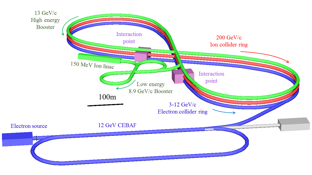
The JLEIC is designed to take advantage of the existing 12 GeV electron SRF recirculating linac CEBAF at Jefferson Lab, which will be used to provide an electron beam for the collider. Both colliding beams will be stored in two figure-8 shaped collider rings. One ring, made of NC magnets, stores electrons at 3 GeV to 12 GeV, with an average beam current of up to 3 A (below 7 GeV). The second ring, consisting of 6T SC magnets, either stores fully-stripped ions, with up to 80 GeV per nucleon, or protons with energies between ranging from 30 to 200 GeV. The two collider rings and the additional 13 GeV/c high energy ion/proton booster ring are stacked vertically, have nearly identical circumferences of 2.3 km, and are housed in the same underground tunnel next to the CEBAF facility, as illustrated in Fig. 18. The unique figure-8 shape of the collider allows complete cancellation of spin precession between the left and right arcs, in which guiding vertical magnetic fields are of opposite directions, thus resulting in zero net spin tune independent of energy. This shape is chosen for optimization and preservation of ion spin polarization during acceleration in the booster and collider rings, as well as during beam storage. The crossing angle of the tunnels is 77.4∘ and electron and ion beamlines intersect at an angle of 50 mrad in two long straights next to the crossing point, allowing accommodation of two detectors. The CEBAF 1.5 GHz linac will serve as a full-energy injector into the 3–12 GeV electron ring, requiring no upgrade for energy, beam current, or polarization. An entirely new hadron-beam complex is required for proton and ion beam generation and acceleration. This complex includes sources for polarized light ions and for non-polarized light to heavy ions; a 150 MeV SRF linac for protons, a compact figure-8 8.9 GeV/c low energy booster ring, and the 13 GeV/c high energy booster ring, which injects into to the main 200 GeV/c proton (or 80 GeV/ ion) ring. Key design parameters of the JLEIC are presented in Table 4. The JLEIC upgrade to 140 GeV c.m.e. will require an increase of the proton energy to 400 GeV through the installation of new 12 T SC magnets.
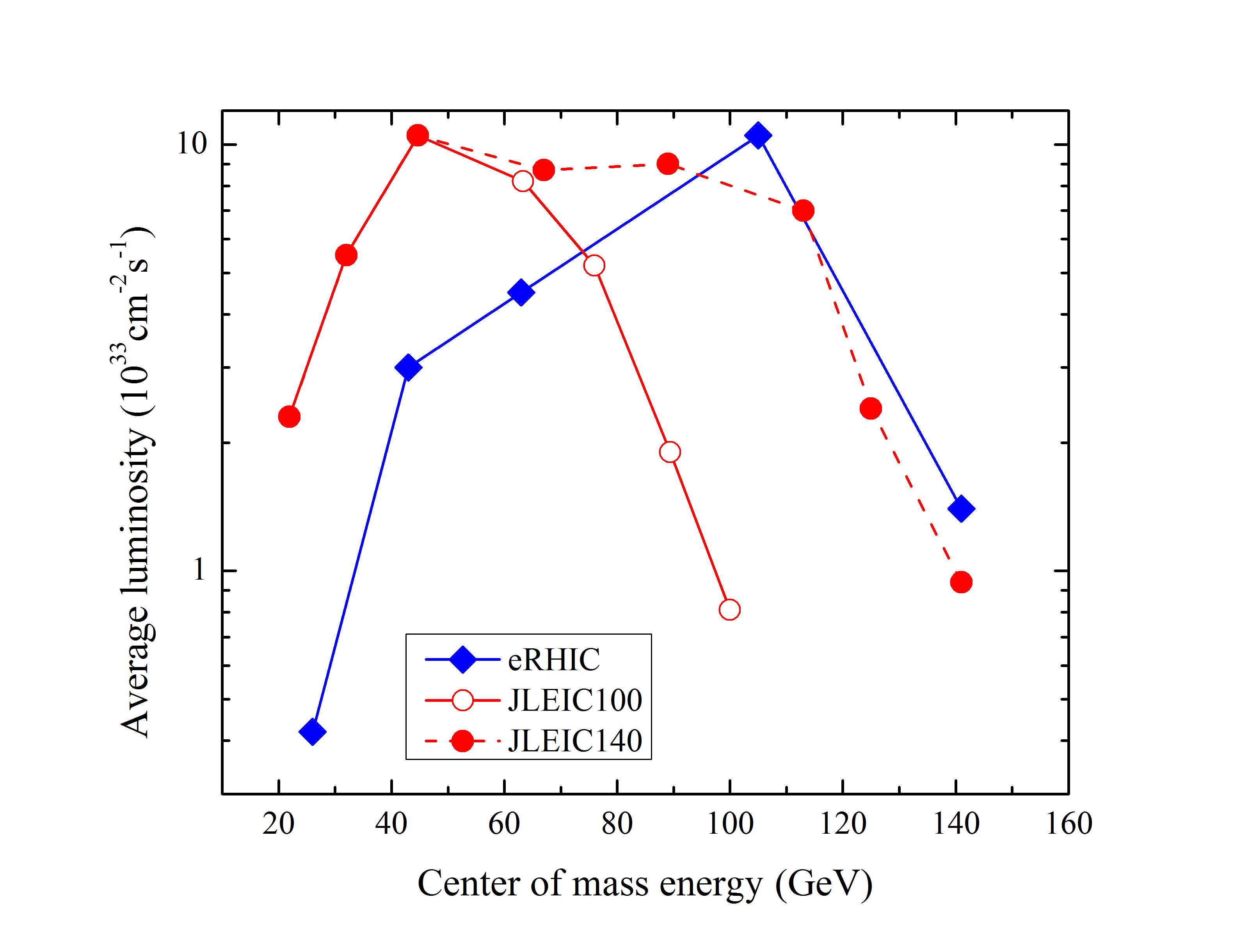
The JLEIC luminosity performance is determined by different limits, depending on c.m.e. (Fig. 19). At 20–35 GeV energies it is limited by space-charge effects for the hadron beams, in the range of 35–60 GeV, by beam-beam effects on both beams, at higher energies by synchrotron radiation of the high energy electron beam Zhang (2019). Synchrotron radiation results in emittance growth and also limits the maximum electron current. The electron current, which is 3 A at energies below 7 GeV, decreases to less than 0.5 A at 12 GeV, if the total radiation power is limited to 10 MW. Hadron beam cooling is needed to combat IBS and to reduce or preserve beam emittances. It, therefore, is critical for the JLEIC and luminosities. A three stage electron cooling is proposed, that includes a conventional 50 kV DC cooler in the low-energy booster ring (for ions), a state-of-the-art 1.1–4.3 MeV DC cooler in the high energy booster ring, and a 43–109 MeV ERL-based cooler in the collider ring (the electron energy range indicates values for lead ions and protons). The required cooling rates call for electron bunches with 3.2 nC charge supplied at the 476.3 MHz repetition rate of the ion bunches, resulting in a 1.5 A beam current, far higher than what has ever been demonstrated in an ERL. To reduce the average electron cooling current, a Circulating Cooler Ring (CCR) concept is proposed, that circulates the high charge bunches 11 times through the cooler before returning them to the ERL Benson et al. (2018). This novel concept needs further development and testing of its key parts such as the fast harmonic transverse kicker needed to kick electrons in and out of a 60 m circulator ring, and the magnetized electron beam generation and transport to assure a low temperature of the electrons and, thereby, a high cooling efficiency.
A beam crossing angle of 50 mrad is necessary to avoid parasitic collisions due to short bunch spacing, make space for machine elements, improve detection and reduce detector background. To prevent a factor of 12 luminosity loss caused by the crossing angle, SRF crab cavities will need to be installed on both sides of each IP, and for both beams, to restore head-on collisions in the center-of-mass frame.
| Parameter | NICA | ELISe | EicC-I | JLEIC | eRHIC | LHeC | |||||
| Species | |||||||||||
| C.m. energy (GeV) | 9 | 1.8 | 16.7 | 44.7 | 105 | 1300 | |||||
| Beam energy (GeV) | 4.5/u | 0.74/u | 0.5 | 20 | 3.5 | 100 | 5 | 275 | 10 | 7000 | 60 |
| Circumference (m) | 503 | 224 | 53.7 | 600 | 800 | 2336 | 3834 | 26700 | 9000 | ||
| Number of bunches | 24 | 40 | 8 | 2000 | 3228 | 1320 | 2808 | n/a | |||
| Particles per bunch (1010) | 0.22 | 8.610-4 | 5 | 0.5 | 3.2 | 1 | 4.7 | 6 | 15.1 | 22 | 0.23 |
| Emittance (H/V,rms norm., m) | 1.1/0.8 | 0.07 | 45 | 1 | 68 | 0.7/0.13 | 83/17 | 9.2/1.6 | 20/1.3 | 1.9 | 53 |
| Beta functions at IP (cm) | 35 | 100/15 | 100/15 | 2/1 | 20/10 | 8/1.3 | 5.7/1 | 91/4 | 41/5 | 7 | 5 |
| Bunch length (rms, cm) | 60 | 15 | 4 | 3 | 10 | 2.5 | 1 | 6 | 1.9 | 7.6 | 0.006 |
| Beam-beam parameter () | 50 | n/a | n/a | 3 | 10 | 15 | 40 | 14/7 | 70/100 | 0.4 | n/a |
| Space-charge param. | 0.05 | 0.08 | n/a | 0.01 | n/a | 0.018 | n/a | n/a | n/a | n/a | n/a |
| IBS time (hor./long., min) | 42 | n/a | 8.3/3.3 | n/a | 0.7/2.3 | n/a | 126/120 | n/a | 4000 | n/a | |
| Polarization | 80% | n/a | n/a | 85% | 80% | 80% | 80% | 0 % | 90% | ||
| Luminosity ( cm-2s-1) | 0.001 | 0.01 | 1.5 | 1.05 | 0.8 | ||||||
The eRHIC design Willeke et al. (2019) aims at polarized electron-proton collisions in the c.m.e. range from 29 to 141 GeV, which are accomplished by colliding 41 to 275 GeV protons delivered by the existing “Yellow Ring” of the RHIC heavy ion collider and the entire existing hadron beam injector chain, with 5 to 18 GeV electrons from a new electron storage ring installed in the RHIC tunnel. The eRHIC peak luminosity reaches about cm-2s-1 at 100 GeV — see Fig. (19). Key parameters of the eRHIC are given in Table 4. Polarized electrons are provided by a full-energy spin-transparent rapid-cycling synchrotron (RCS) using normal-conducting RF cavities, located in the 3.8 km RHIC tunnel. The RCS is specifically designed to be free of intrinsic resonances over the entire acceleration range from 400 MeV at injection to 18 GeV. Spin transparency is achieved by a high super-periodicity of the RCS focusing lattice of =96, and an integer tune of =50. With such parameters, intrinsic spin resonances, which occur under condition Lee (1997):
| (32) |
(here, is an integer, = 0.00115965 is the anomalous gyromagnetic ratio of the electron, is the relativistic Lorentz factor), are avoided over the entire energy range of the RCS and the simulated polarization transmission efficiency is about 97%, even in the presence of magnet misalignments as large as 0.5 mm rms.
Focusing for the electron storage ring is achieved through 16 FODO cells in each of the six arcs. To obtain the required design emittance over the entire energy range from 5 to 18 GeV, the ring operates with different betatron phase advances per FODO cell — 90 degrees at 18 GeV, and 60 degrees at 10 GeV and below. The bending sections in these cells are realized as super-bends, with each section consisting of three individual dipoles, namely two 2.66 m long dipoles with a short (0.44 m long) dipole in-between. At beam energies of 10 GeV and above, all three segments are powered uniformly for a smooth, uniform bend, while at 5 GeV, the polarity of the short center dipole is reversed, resulting in additional synchrotron radiation in this configuration to provide the required fast radiation damping enabling the high electron beam-beam parameter of 0.1. The total electron beam intensity is set by a 10 MW power limit on the ring SRF system, which must restore the synchrotron radiation losses. Arbitrary spin patterns in the electron storage ring — with simultaneous storage of bunches with spin “up” and bunches with spin “down” in the arcs — are achieved by injecting polarized electron bunches with the desired spin orientation at full storage energy. Since the Sokolov-Ternov effect Sokolov and Ternov (1964) will lead to depolarization of bunches with spins parallel to the main dipole field, a frequent replacement of individual bunches is required, at a rate of about one bunch per second, to keep the time-averaged polarization sufficiently high.
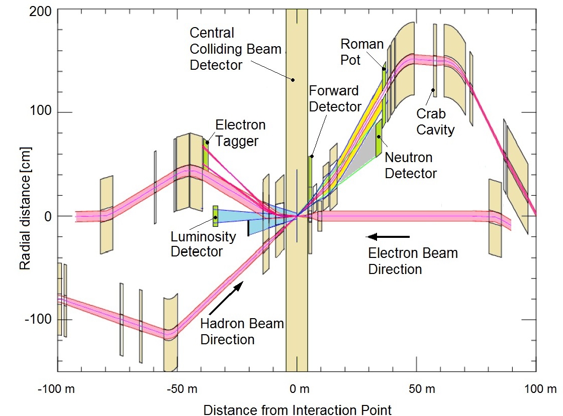
The beams of electrons and ions (or protons) collide in one or two interaction regions at a 25 mrad crossing angle. Different frequency choice for the eRHIC crab cavity systems have been considered. For example, a combination of 200 and 400 MHz for the long proton bunches, and of 400, 800, 1200, and 1600 MHz for the shorter electron bunches would avoid the luminosity reduction due to the crossing and minimize hadron beam emittance growth to less than 5%/h. An alternative, technically simpler option would use 200 MHz crab RF systems for both protons and electrons Verdu-Andres and Wu (2019). A dedicated fill pattern ensures that each bunch collides only once per turn. This way, luminosity is shared equally between the two detectors without exceeding the beam-beam limit. To maximize luminosity, the beams are focused to flat cross sections at the IP. Sophisticated interacting region optics (see Fig. 20) provides sufficient separation of the hadron beam from the 5 mrad forward neutron cone, separates the electron beam from the Bethe-Heitler photons used for luminosity measurements, and allows for a safe passage of the synchrotron radiation fan generated upstream of the IP through the detector.
The hadron beam parameters are similar to what has been achieved in the RHIC, with the exception that the number of bunches will be increased from 110 in the present RHIC up to 1320 (or 1160) in the eRHIC, while increasing the total hadron beam current by a factor of three. The higher current could cause unacceptable heating of the cryogenic stainless-steel beam pipes. A thin layer of copper will, therefore, be applied in-situ, to improve the beam-pipe surface conductivity. A much thinner layer of amorphous carbon will next be deposited on top of the copper coating to reduce secondary electron yield and, thereby, suppress the formation of electron clouds. A broad spectrum of desired center-of-mass collision energies implies operation over a wide range of ion energies and, therefore, substantially different ion velocities. In order to maintain the synchronization between electron and hadron beams, the circumference of one of the two rings has to be adjusted. This is accomplished by two methods: between 100 and 275 GeV proton energy, a 14 mm radial orbit shift is sufficient to account for variations in velocity of the hadron beam. For proton beam operation at 41 GeV, the beam will travel through the (inner) “Blue” arc of the RHIC between interaction regions IR12 and IR2 instead of the (outer) “Yellow” arc, thus reducing the circumference by 93 cm.
Usable store length in the eRHIC collider is limited by IBS growth time of approximately 2 hours. Since the turnaround time between stores is of the order of 30 min, average luminosity would only be about half the peak value. To counteract the fast emittance growth due to IBS and, hence, to increase usable store length, strong hadron cooling with some 1 hour cooling time is required. Two cooling schemes are currently under consideration: a somewhat conventional cooling with a bunched electron beam, or variations of coherent electron cooling, where an electron beam is used as a pickup and kicker in a very high bandwidth stochastic cooling scheme Litvinenko and Derbenev (2009). The feasibility of the former, based on the electron RF photoinjector system has recently been demonstrated Kayran et al. (2019, 2020), but the required high beam intensities for a bunched beam electron cooler for eRHIC by far exceed the capabilities of present-day electron guns. An alternative scheme, in which the electron beam is stored in a small storage ring equipped with strong damping wigglers, is being evaluated. Coherent electron cooling has not yet been demonstrated experimentally. An alternative could, therefore, be to use the existing “Blue” ring as a full-energy injector to cool proton/ion bunches at (or slightly above) 25 GeV injection energy, which is much easier due to strong energy dependence of cooling forces, and then to ramp the “Blue” ring and replace the entire fill in the “Yellow” storage ring every 15 min. Yet another possible design scenario, without any hadron cooling, results in optimized machine parameters yielding a (peak) luminosity of 0.44 cm-2s-1. In general, hadron cooling is one of the most important topics of the ongoing eRHIC R&D program, together with the development of the required crab cavities, efficient SRF for the electron storage ring, and fast kickers to manipulate the significantly increased number of bunches.
Early in 2020, the U.S. Department of Energy (DOE) announced that the Electron-Ion Collider will be built at Brookhaven National Laboratory in Upton, New York Cho (2020).
IV.1.4 LHeC, HE-LHeC and FCC-eh
Deep inelastic scattering of electrons on protons or nuclei has traditionally proven the best means to probe the inner structure of nucleons and nuclei. A unique opportunity for this can be offered by colliding 7 TeV protons circulating in the LHC with 60 GeV electrons from an energy recovery linac (ERL) Kuze (2018). Since such a Large Hadron electron Collider (LHeC) LHeC Study Group: Abelleira Fernandez, J L, et al (2012) uses a beam of the already built hadron collider, it can be realized at an affordable cost and can run concurrently with hadron-hadron collision experiments. The LHeC can provide much cleaner collision environment at =1.3 TeV and would be another powerful tool to study Higgs boson properties Zimmermann et al. (2013); Mellado (2013).
The electron ERL is of racetrack shape, accommodating two 10 GeV SC linacs in the straights, connected by arcs with a bending radius of about 1 km. The LHeC linacs employ SC bulk Nb cavities with a frequency of 800 or 400 MHz. Three acceleration passages are required to attain the design electron energy of 60 GeV at the IP, followed by three turns of deceleration for energy recovery (the basic ERL principle is sketched in Fig. 39). The total circumference of the baseline LHeC is exactly one third of the LHC, easing the introduction of electron bunch gaps for ion clearing without perturbing the proton beam. Smaller circumferences (one fourth, one fifth) are also possible at the price of lower electron beam energy.
The IP beam size of the LHeC is determined by the emittance and minimum of the proton beam — see Table 4. Luminosity is then set by the electron beam current. A luminosity of order 1034 cm-2s-1 is required for Higgs boson physics studies Zimmermann et al. (2013), demanding a high average electron beam current of 20–30 mA at the collision point, that in turn can only be achieved with energy recovery. The 3-pass beam recirculation including energy recovery implies a six times higher current in the SC linacs, which simultaneously accelerate three beams of different energies and decelerate three other beams. Construction of a high-current multi-turn 500 MeV ERL test facility for the LHeC, called PERLE, is planned at LAL in Orsay Angal-Kalinin et al. (2018). PERLE will demonstrate the technical feasibility of the LHeC concept. At the end of 2019, an already constructed multi-pass ERL test facility of a different type, CBETA at Cornell, has achieved 4 turns of acceleration followed by 4 turns of deceleration BNL Newsroom: Transformative ‘Green’ Accelerator Achieves World’s First 8-pass Full Energy Recovery , albeit at a much lower beam current than required for the LHeC (also see Ch. V.2). The LHeC cost and AC wall plug power estimates are 1.8 BCHF and 100 MW, respectively Bruning (2018). A 30 GeV electron ERL version of the LHeC will cost below 1 BCHF, at approximately the same luminosity and operation cost. Such a version is studied as a possible first stage assuming that the c.m.e. reach can later be increased by accepting a slightly higher power consumption and better SRF performance.
The same or a similar ERL could be used to realize electron-hadron collisions also at the High-Energy LHC (HE-LHeC, with twice the LHC’s proton energy) or at the FCC-hh (FCC-eh, with 7–8 times more energetic protons) — see Chapter IV.3. Luminosities for HE-LHeC and FCC-eh are above cm-2s-1 at =1.8 TeV and =3.5 TeV, respectively Bruning et al. (2017).
IV.2 Lepton colliders studying Higgs boson and electroweak sector
Higgs factory proposals generally aim at improving the precision of coupling measurements of Higgs boson, top quark, and by an order of magnitude or more compared with previous studies.
The International Linear Collider (ILC), with a center of mass energy of 250 GeV in collisions, has been under consideration for more than two decades and could potentially be upgraded to =500 GeV and further to 1 TeV. CERN’s Compact Linear Collider (CLIC) design, developed since the mid-1980s, also includes possible upgrades, from an initial 380 GeV c.m.e. to ultimately 3 TeV, which would enable searches for new particles of significantly higher masses.
Two proposals for circular colliders have appeared more recently: the “Future Circular Collider” (FCC-ee) at CERN Benedikt et al. (2019a) and the “Circular Electron-Positron Collider” (CEPC) in China CEPC Study Group (2018). These ambitious, large-scale projects based on well-established technologies are not extendable to TeV or multi-TeV energies, but offer several important advantages that include the potential for much higher luminosities and, thus, higher precision, the ability to operate multiple experiments simultaneously, and their 100 km circular tunnels that could later house (100 TeV) hadron colliders.
At lower energies, the main aim of the proposed Super Tau-Charm Factories is the production and precise study of charmonium states and of the tau lepton.
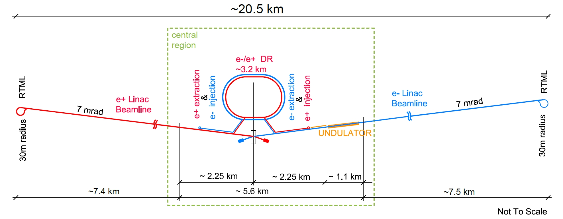
IV.2.1 Super -Charm Factories
Two Super Tau-Charm Factories are being proposed, in Russia (SCT) Piminov (2018) and in China (HIEPA) Luo et al. (2019), respectively. They will provide excellent possibilities in search for new physics and for detailed studies of known phenomena. Both proposals consider double ring e+e- colliders operating at c.m.e. between about 2 and 7 GeV. Their design luminosity is 2 or 1 times cm-2s-1, achieved with (0.6) mm and a crab-waist collision scheme. The expected beam lifetime is about 10 minutes, supported by top-up injection, requiring a positron production rate of up to 1011/s. The electron beam can be longitudinally polarized at the collision point. Preliminary conceptual designs are available for both projects. Numerous synergies and complementarity exist between the two Super -charm factory projects, the already constructed SuperKEKB, and the proposed future higher-energy circular Higgs factories FCC-ee and CEPC — see Section IV.2.3.
IV.2.2 Linear colliders for Higgs sector: ILC and CLIC
As noted above, linear colliders are (almost) free of synchrotron radiation losses and their energy scales with the gradient and length of their accelerating sections — see Eq. (4). Beam acceleration by a sequential array of RF cavities is by itself a straightforward technique to reach the c.m.e. required for Higgs boson studies in collisions. The main challenge in designing a high energy, high luminosity single pass collider is the power requirement. Indeed, luminosity of a linear collider is constrained by three limiting factors (in parentheses):
| (33) |
where the first factor is proportional to the total beam current, set by particle sources (especially challenging is the positron production; see below), by coherent beam instability concerns, and most importantly, by the available RF power. If the total AC wall-plug power of the collider is and efficiency of converting it into beam power is , then . The efficiency of the RF system, the largest and most critical part of total efficiency , is usually less than 10% Delahaye (2016), and it constitutes the biggest technological challenge for linear colliders. The second factor in the luminosity equation calls for ultra-small vertical beam size at the IP, , that in turn requires record small beam emittances formed in dedicated damping rings Emma and Raubenhemier (2001), precise (10m) mechanical and beam-based alignment, stabilization of focusing magnets and accelerating cavities at the nm level Baklakov et al. (1994); Sery and Napoly (1996); Baklakov et al. (1998); Shiltsev (2010a), and beam position monitors (BPMs) with 0.1 m resolution, in order to obtain the rms beam sizes of 8 nm (vertical) and 520 nm (horizontal) at the ILC IP and of 3 nm/150 nm at the CLIC IP Raubenheimer (2000); Kubo (2011); Pfingstner et al. (2017).
The third factor in Eq. (33) defines the beam energy spread and the degradation of the luminosity spectrum arising from the so-called beamstrahlung radiation of photons and pairs in the strong electromagnetic (EM) fields of the tightly compressed opposite bunch Bell and Bell (1995); Chen (1992). This effect grows with collision energy. For example, it amounts to 1.5% in the 250 GeV c.m.e. ILC, while in the 380 GeV CLIC it already results in some 40% of the collider luminosity being more than 1% away from the maximum c.m.e. The management of leads to an upward push on the bunch population and, therefore, on the number of beamstrahlung photons emitted per which is approximately equal to , where denotes the fine-structure constant Zimmermann (2001). Typically, one aims for , to retain a significant luminosity fraction close to the nominal energy. A consequence is the use of flat beams, where is controlled by the beam width , and the luminosity is adjusted through the beam height , motivating the extremely small vertical small sizes at both ILC and CLIC. The final factor in Eq. (33), , represents the enhancement of luminosity due to the pinch effect, i.e., the additional focusing occurring during the collision of oppositely charged bunches; typically assumes values between 1 and 2.
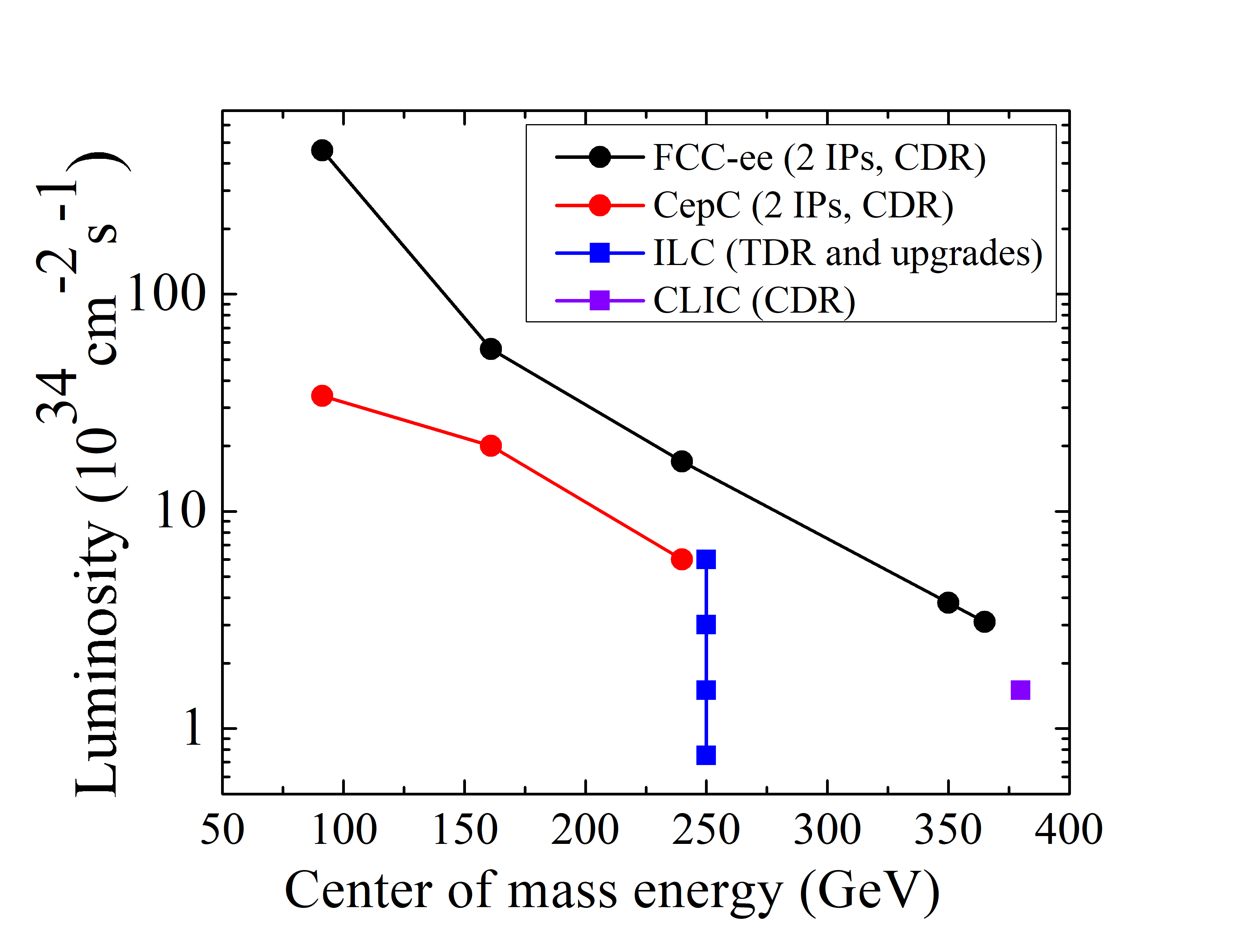
The ILC Technical Design Report Adolphsen et al. (2013) (TDR) foresaw a baseline c.m.e. of 500 GeV, with a first stage at 250 GeV, and upgrade provision for 1 TeV, at luminosity values comparable to the LHC’s. Recent revisions, motivated by the low mass of the Higgs boson, have established new optimized configurations for collisions at 250 GeV Evans and Michizono (2017); Aihara et al. (2019). The ILC employs 1.3 GHz SRF cavities made of bulk Nb, operating at an accelerating gradient of 31.5 MV/m at 2 K, and it requires some 130 MW of site power — see the key machine parameters in Table 5. The 1.3 GHz pulsed SRF technology of the ILC was developed for the TESLA project Aune et al. (2000) and successfully applied for the European X-Ray Free Electron Laser Altarelli et al. (2006). Progress toward higher field gradients and values of SC cavities continues to be made, with nitrogen doping, nitrogen-diffusion techniques, and Nb3Sn cavities being recent examples Grassellino et al. (2013); Dhakal et al. (2015); Padamsee (2019).
Figure 21 presents a schematic overview of the ILC with its main subsystems. The accelerator extends over 20.5 km, dominated by the main electron and positron linacs and another 5 km of beam delivery and final focus system. It consists of two main arms intersecting at a 14 mrad crossing angle. Electrons with 90% polarization are produced by an electron gun, where a Ti:sapphire laser pulse hits a photocathode with a strained GaAs/GaAsP superlattice structure. The baseline solution for ILC positron production employs a 320 m long SC helical undulator with 5.85 mm diameter beam aperture, located at the end of the 125 GeV electron main linac Alharbi et al. (2019). When the main electron beam passes through this undulator it produces polarized photons that are converted to positrons, in a rapidly rotating target (2000 rounds per minute), resulting in 30% longitudinal positron polarization. An alternative design, which does not require a fully operational main linac, instead utilizes a separate, dedicated 3 GeV electron accelerator to produce positrons via conventional pair production, when the electron beam hits a target (no positron polarization provided in that case). After acceleration to 5 GeV, electrons and positrons are injected into the centrally placed 3.2 km-long damping rings, each equipped with 54 SC wigglers, needed to assist fast damping of the beam’s initially large normalized emittances to 20 nm (4 m) in the vertical (horizontal) plane within the 200 (100) msec time between collider shots with repetition frequency (10) Hz. Next is the Ring-to-Main-Linac (RTML) system that includes beamlines to transport the low-emittance beams to the beginning of the main accelerators where two-stage bunch compressors squeeze the longitudinal bunch length to 0.3 mm, and the beam energy increases from 5 GeV to 15 GeV, before the beams are sent into the main linacs to be accelerated to 125 GeV each.
The main linacs accelerate the beams in SC Nb cavities, each 1.04 m long and having 9 cells, with a mean accelerating gradient of 31.5 to 35 MV/m — see Fig. 5. Cryomodules of 12 m length provide cooling and thermal shielding of the cavities; these contain all necessary pipes for liquid and gaseous helium at various temperatures and house 9 or 8 such cavities plus a quadrupole unit for beam focusing. The RF power for the cavities is generated by commercially available 10 MW klystrons, with a peak efficiency of 65%. Finally, the beam-delivery system focuses the beams to the required size of 516 nm 7.7 nm at 250 GeV c.m.e. It is expected that the electron beam polarization at the IP will be 80% (i.e., only 10% off its original level) and that the vertical beam emittance will not be more than 75% above its original damping ring value. A feedback system, which profits from the relatively long train of 1312 bunches with inter-bunch separation of 554 ns, shall ensure the necessary beam-beam pointing stability at the IPs. The ILC is designed to allow for two detectors mounted on movable platforms and operated in a so-called push-pull mode; these detectors can be moved into and out of the beam within a day or two.
Besides energy upgrades to =0.5 Tev and 1.0 TeV, luminosity upgrades are also possible by doubling the number of bunches per pulse to 2625 at a reduced bunch separation of 366 ns (which would require 50% more klystrons and modulators and an increased cryogenic capacity), and by an increase in the pulse repetition rate from 5 to 10 Hz (which would require a significant increase in cryogenic capacity, or running at a reduced accelerating gradient after an energy upgrade). The corresponding points are indicated in Fig. 22.
After the discovery of the Higgs boson in 2012, the Japan Association of High Energy Physicists (JAHEP) made a proposal to host the ILC in Japan and the Japanese ILC Strategy Council conducted a survey of possible sites for the ILC in Japan, eventually selecting a suitable one in the Kitakami region of Northern Japan Bambade et al. (2019). The cost of the 250 GeV ILC project in Japan is estimated at 700 BJPY (with 25% uncertainty, including cost of labor).
The Compact Linear Collider (CLIC) is a TeV-scale high-luminosity linear collider proposal, that envisions three stages of construction and operation at c.m.e. of 380 GeV, 1.5 TeV, and 3 TeV, and a site length ranging between 11 km and 50 km. What makes it distinct from the ILC is its novel two-beam acceleration scheme, in which NC copper high-gradient 12 GHz accelerating structures are powered by a high-current 1.9 GeV drive beam to efficiently enable an accelerating gradient of 100 MV/m, about three times the gradient of the ILC. For the first CLIC stage at =380 GeV, suitable for Higgs boson studies, the optimum gradient turns out to be a little lower, 72 MV/m Robson et al. (2018), and for this stage an alternative RF power drive option with 12 GHz klystron powering is also being considered Aicheler et al. (2019). The main parameters of CLIC are given in Table 5.
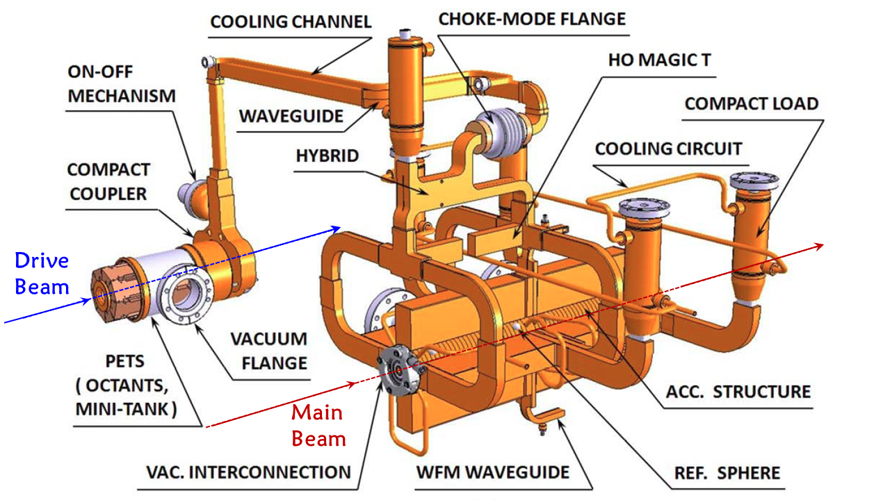
CLIC two-beam configuration is implemented by using two distinct parallel linear RF accelerating structures some 0.6 m apart, connected by a waveguide network; see Fig. 23. A low-impedance power extraction and transfer structure (PETS, of about 0.3 m length with 23 mm aperture) resonantly decelerates the drive beam consisting of 12 GHz bunches with an average gradient of about MV/m. The kinetic energy of the drive beam is efficiently converted into the energy of 12 GHz EM waves which are extracted and sent to power two high-impedance accelerating structures (each 23 cm long, with 5 mm aperture) to accelerate the main beam with gradient up to 100 MV/m. The maximum gradient must be achieved at nominal pulse length and shape (156 ns flat-top, 240 ns full length) and with a breakdown rate (BDR) of less than — low enough for the reliable operation of some 20,000 structures in two linacs. This is one of the CLIC challenges, as an empirical scaling law Grudiev et al. (2009) relates the breakdown rate, the gradient , and the RF pulse length approximately via
| (34) |
Figure 24 presents a schematic layout of the CLIC complex. The main spin-polarized beam is produced on a strained GaAs cathode in a conventional RF source and accelerated to 2.86 GeV. The beam emittance is then reduced in a damping ring. For positron beam production, a dedicated 5 GeV linac sends electrons onto a crystal to produce energetic photons, which in turn hit a second target to produce . These positrons are captured, accelerated to 2.86 GeV and sent through a series of two emittance damping rings. The CLIC RTML system accelerates 352 bunches, with 0.5 ns bunch spacing, in each electron and positron beam to 9 GeV, and compresses their bunch lengths to 70 m rms (or 44 m for higher c.m.e.).
After the main linacs have accelerated the beams to 190 GeV, collimators in the beam delivery system remove any transverse tails and off-energy particles, and finally the final focus magnets compress the beams to the required small transverse sizes at the collision point. After the collision, the spent beams are transported to a beam dump.
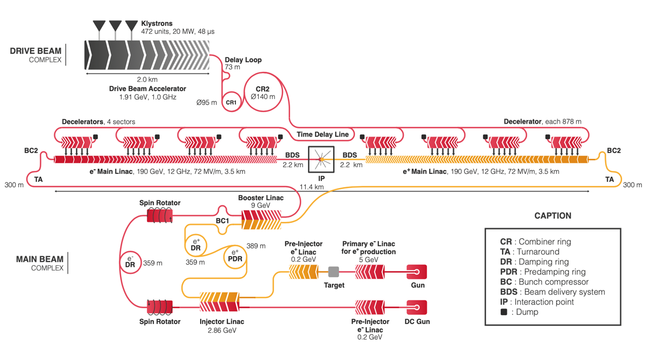
Every 1/(50 Hz)=20 ms, the 20 MW drive beam (1.91 GeV, 101 A) is generated in a 48 s long pulse of bunches spaced by 0.6 m in a central complex with a 1 GHz fundamental frequency of its 472 klystrons. After a sequence of longitudinal manipulations, involving a delay line and two combiner rings, the initial beam is transformed into two series of four 244 ns long final sub-pulses with a 12 GHz bunch spacing of 2.5 cm (i.e., 24 times the initial beam current) which are sent in opposite directions to power the two linacs. The first sub-pulse in each linac powers the first drive-beam decelerator, running in parallel to the colliding beam. When this sub-pulse reaches the decelerator end, the second sub-pulse has reached the beginning of the second drive-beam decelerator and will power it, running in parallel to the colliding beam, and so on.
The CLIC luminosity critically depends on beam emittances (particularly vertical ones) at collision at the IP, requiring generation of and beams with a minimum emittance and their tight preservation during acceleration and focusing. The latter calls for control of all relevant imperfections, such as pre-alignment of all the main linac and beam delivery system components at the 10 m level, suppression of vibrations of the quadrupoles due to ground motion to the level of 1.5 nm at frequencies above 1 Hz for the main linac (and to 0.2 nm above 4 Hz in the final focus system) Collette et al. (2010), novel beam-based trajectory tuning methods to minimize the effect of dynamic and static imperfections using submicron resolution BPMs Eliasson (2008); Balik et al. (2013), and mitigation of the effect of wakefields caused by high current beams passing through misaligned accelerating structures. As a net result, between the damping ring and the IP, the CLIC vertical normalized emittance increases by less than a factor of 4.
CLIC accelerator design, technical developments and system tests have resulted in a high energy efficiency, and a correspondingly low power consumption of around 170 MW for the 380 GeV stage, and a machine total cost estimate of approximately 6 BCHF Aicheler et al. (2019).
There has been remarkable progress in linear collider R&D in recent years. Beam accelerating gradients met the ILC goal of 31.5 MV/m at the Fermilab FAST facility in 2017 Broemmelsiek et al. (2018) and at KEK in 2019, and exceeded CLIC specifications at the CLEX facility at CERN, where the drive beam was used to accelerate the main beam with a maximum gradient of 145 MV/m Robson et al. (2018). The Accelerator Test Facility in KEK has also demonstrated attainment of the required vertical beam emittance in the damping ring and focusing of that beam into 40 nm vertical rms beam size Bambade et al. (2010).
Higgs Factory proposals based on linear colliders offer several advantages: they are based on mature technologies of NC RF and SRF that have been well explored at several beam test facilities. Their designs have been developed to a sufficient level of detail. At present the ILC design is described in a TDR and the design of CLIC in a comprehensive conceptual design report (CDR). Advantageous for HEP research is also beam polarization (80% for and 30% for at the ILC; 80% for and 0% for at CLIC). Linear colliders are expandable to higher energies (ILC to 0.5 and 1 TeV, CLIC to 3 TeV). Both proposals have well established international collaborations, which indicate readiness to start construction soon; their demand for AC wall plug power of 130–170 MW is less than that of the LHC complex (200 MW).
At the same time, one has to pay attention to the following factors: (i) the cost of these facilities equals or somewhat exceeds the LHC cost; (ii) the ILC and CLIC luminosity projections are in general lower than those for rings (see Fig. 22 and discussion below), and luminosity upgrades (such as via a two-fold increase of the number of bunches and doubling the repetition rate from 5 Hz to 10 Hz in the ILC) will probably come at additional cost; (iii) operational experience with linear colliders is limited only to SLAC’s SLC, whose ten-year commissioning experience hints the possible operational challenges; (iv) the CLIC’s two-beam scheme is quite novel (klystrons are therefore a backup RF source option); and (v) AC wall plug power demand may grow beyond 200 MW for the proposed luminosity and energy upgrades.
Linear colliders for TeV and multi-TeV c.m.e. face even more formidable challenges: their lengths grow to 40–50 km, AC power requirements become 300–600 MW, the beamstrahlung leaves only 30–40% of the luminosity within 1% of maximum energy (see Fig. 25) and project costs grow to $17B for 1 TeV ILC (the TDR cost estimate) and 18.3 BCHF for 3 TeV CLIC (CDR).
To reach their design luminosities, both CLIC and ILC require unprecedented rates of positron production. The ILC baseline foresees about 40 times the world record set by the SLC positron source, and the ILC luminosity upgrade calls for improvement by another factor of four. Figure 26 compares the demonstrated production rates at the SLC, KEKB, and SuperKEKB with the needs for top-up injection at future circular colliders, and at the collision point of future linear colliders.
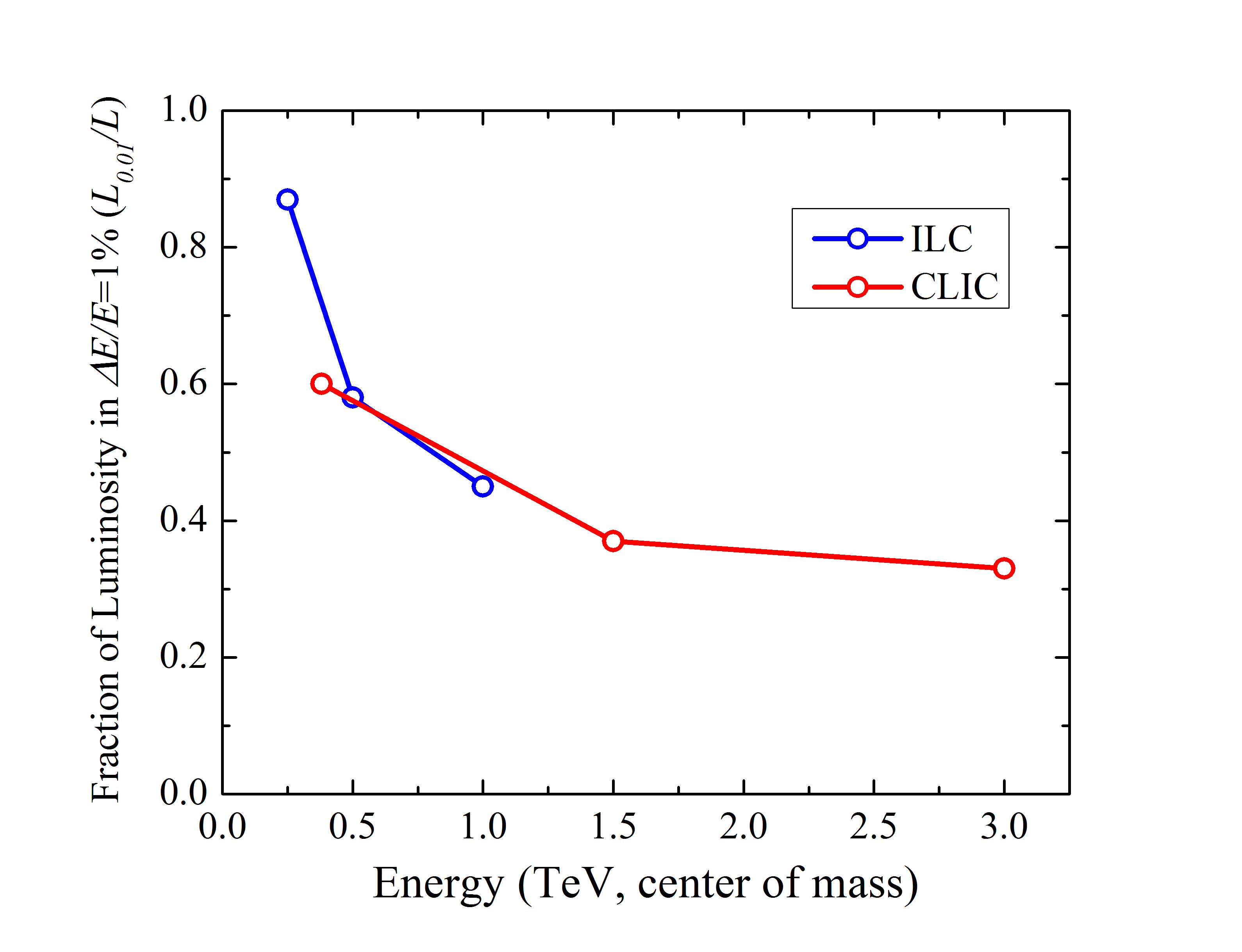
IV.2.3 Circular colliders for the electroweak sector: FCC- and CEPC
The 2012 discovery of the Higgs boson at the LHC has stimulated interest in circular Higgs factories Blondel et al. (2013), and in particular, in the construction of a large circular tunnel which could host a variety of energy-frontier machines, including high-energy electron-positron, proton-proton, and lepton-hadron colliders. Such projects are being developed by the global Future Circular Collider (FCC) collaboration hosted at CERN Benedikt et al. (2019a) and, in parallel, by the Circular Electron-Positron Collider (CEPC) study group based in China CEPC Study Group (2018), following an earlier proposal for a Very Large Lepton Collider (VLLC) Sen and Norem (2002) in the US, which would have been housed in the 230-km long tunnel of the Very Large Hadron Collider (VLHC) Ambrosio et al. (2001).
In order to serve as a Higgs factory, a new circular e+e- collider needs to achieve a c.m.e. of at least 240 GeV Benedikt et al. (2019b). The unprecedentedly high target luminosity of FCC-ee and CEPC implies a short beam lifetime,
| (35) |
of order 1 hour, due to the unavoidable radiative Bhabha scattering with a cross section of mbarn Burkhardt and Kleiss (1995). In Eq. (35) signifies the number of bunches, the number of collision points, and the bunch population. The short beam lifetime due to radiative Bhabha scattering, which can be further reduced by beamstrahlung (see below), is sustained by quasi-continuous top-up injection. The technique of top-up injection was routinely and successfully used at both PEP-II and KEKB Seeman (2015); Satoh (2010), where physics runs with nearly constant beam currents and constant luminosity were only occasionally interrupted (e.g., a few times per day) by fast beam aborts due to hardware failures. Top-up injection for FCC-ee or CEPC calls for a full-energy fast-ramping booster ring, with the same circumference as the collider, i.e., installed in the same tunnel.

At high energy, the performance of a circular collider is limited by synchrotron radiation. The maximum beam current is directly proportional to synchrotron radiation power , and to the bending radius , and it scales with the inverse fourth power of the beam energy or the Lorentz factor , that is (see Eq. (9)). Correspondingly, the luminosity Eq. (28) scales as the product of the ring radius , beam-beam parameter , beta-function at the IP , and the RF power , and with the inverse of . The beam-beam parameter is limited to about =0.13 by a new type of beam-beam instability occurring for collisions with a nonzero crossing angle Ohmi et al. (2017); Kuroo et al. (2018). Average beam energy loss per turn due to the synchrotron radiation varies between 0.1 and 5% (from energy to 365 GeV), and, at the higher energies, it is significantly larger than the equilibrium energy spread due to beamstrahlung, which can be of order 0.1–0.2%. It is worth noting that, in the lower energy running modes of the circular Higgs/electroweak factories ( and runs), the beamstrahlung significantly increases the energy spread and bunch length, by up to a factor of 3–4 over what would be obtained without collisions, i.e. with the natural bunch length set by the quantum fluctuation in the low-field collider arcs. This large relative increase of the energy spread due to beamstrahlung is due to the weak radiation damping at these lower energies, where each electron, or positron, emits multiple beamstrahlung photons during one radiation damping time. At the higher beam energies, especially for operation, radiation damping is stronger and the energy spread increase due to beamstrahlung becomes much less pronounced. However, here the single emission of hard beamstrahlung photons at the collision point introduces an additional limit on the beam lifetime Telnov (2013), which is about 20 minutes even in a sophisticated crab-waist optics with – mm with large energy acceptance Bogomyagkov et al. (2014b).
The FCC-ee would be installed in a 100 km tunnel, which can afterwards host a 100 TeV hadron collider (FCC-hh, see below). The FCC complex would be connected to the existing CERN infrastructure. CEPC is a project under development in China CEPC Study Group (2018), that is similar to FCC-ee. CEPC would also be followed by a highest-energy hadron collider in the same tunnel, called the Super proton-proton Collider (SppC).
FCC-ee operation is staged, starting on the pole (91 GeV c.m.e.) with approximately the luminosity of the previous LEP collider, then operating at the threshold (160 GeV), followed by the Higgs production peak (240 GeV), and finally at the threshold (365 GeV). An optional FCC-ee run at 125 GeV for direct Higgs production with monochromatization Valdivia García and Zimmermann (2019) could access the Higgs-electron Yukawa coupling d’Enterria (2017); Blondel and Janot (2019). Possibly this constitutes the only available path to address the origin of the electron mass. On the pole and at the threshold, radiative self polarization allows for an extremely precise c.m.e. energy calibration, at the level, based on resonant depolarization Blondel et al. (2019). Even at the highest FCC-ee collision energy, 365 GeV c.m.e., the luminosity, limited by 100 MW of synchrotron radiation power, would still exceed 1034 cm-2s-1 at each of two or four collision points. The FCC-ee SRF system is optimally adapted for each mode of operation, i.e., it is optimized for the respective beam current and the RF voltage required. Specifically, at the pole, the FCC-ee deploys single-cell 400 MHz Nb/Cu cavities, while at the threshold and the production peak 400 MHz five-cell Nb/Cu cavities will operate at 4.5 K. For running they will be complemented by additional 800 MHz bulk Nb cavities at 2 K. At the energy, the RF cavities are shared by the two beams, in common RF straights, which saves cost and is possible thanks to the small number of bunches in this mode of operation.
CEPC operation is scheduled to start at the Higgs production peak (240 GeV c.m.e.), continues on the Z pole (91 GeV), and ends with the WW threshold (160 GeV). Operation at the energy is not foreseen – see Fig. 22. CEPC deploys the same 650 MHz bulk Nb cavities at all beam energies. However, the total number of installed RF cavities varies from 240 (240 GeV) over 120 (91 GeV) to 216 (160 GeV), in the three modes of operation. At the highest (initial) center-of-mass energy of 240 GeV the 240 installed cavities are shared by the two beams. The impedance and higher-order mode power of the 650 MHz RF cavities limit the projected CEPC luminosity at the pole to a value about an order-of-magnitude lower than for FCC-ee (Fig. 22).
The optics designs of FCC-ee Oide et al. (2016) and CEPC contain several novel features, which boost their performance. For the crab waist collision scheme, a large crossing angle is needed and 30 mrad was found to be optimal for FCC-ee; for CECP a similar value of 33 mrad has been chosen. The two colliding beams always approach the IP from the inside, with bending magnets on the incoming side selected to be so weak that, for the FCC-ee, the critical energy of the photons emitted towards the detector stays below 100 keV over the last 450 m from the IP, even at the highest beam energy for operation (365 GeV c.m.e.). Similarly, for CEPC in production mode (240 GeV), the critical energy of the synchrotron-radiation photons is less than 120 keV over the last 400 m upstream of the IP.
As a result, the FCC-ee and CEPC final focus optics are asymmetric (see Fig. 27 for the FCC-ee). Figure 28 illustrates how asymmetric bending also separates the FCC-ee collider IP from the beam line of the full-energy top-up booster by more than 10 meters, leaving sufficient space for the experimental detector. The CEPC layout is similar.
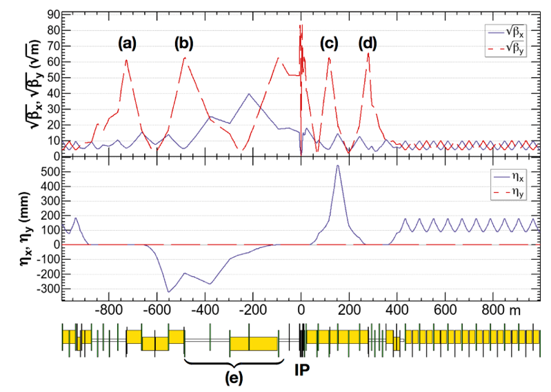
Stronger magnets and a shorter final focus system are installed on the outgoing side of the IP. Each final focus accommodates a pair of sextupoles, separated by a minus identity () optics transformer, to accomplish a local correction of the vertical chromaticity. Thanks to the transformer, geometric aberrations can be exactly cancelled between the two sextupoles of a pair. However, by construction, the dominant aberration generated when reducing the strength of the outer sextupole of the pair generates the desired crab waist at the IP, while maintaining the chromatic correction. Hence, instead of adding one more sextupole as for the crab-waist implementation in other colliders, the FCC-ee utilizes an elegant and novel “virtual crab waist” scheme. Here, the total number and strength of nonlinear magnets is even reduced, compared with the case of no crab waist, with a positive effect on the dynamic aperture.
Both FCC-ee and CEPC proposals call for very high SRF power transfer to beams (100 MW in FCC-ee and 60 MW in CEPC), leading to total site power of about 300 MW. Cost estimate of the FCC-ee is 10.5 BCHF (plus additional 1.1 BCHF for the option to operate at the higher energy) and $5B to $6B for the CEPC (“less than 6 BCHF” cited in the CEPC CDR).
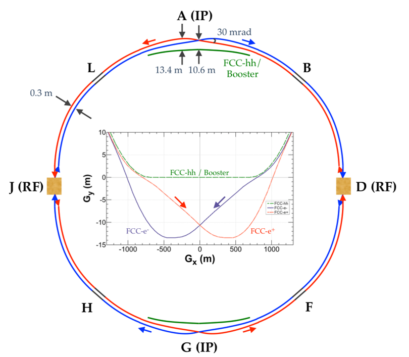
The advantages of circular Higgs Factories include a quite mature SRF acceleration technology, with vast operational experience from numerous other rings, suggesting a lower performance risk, along with a higher luminosity and better luminosity/cost ratio. They can also host detectors at several (2 to 4) IPs, which could further strengthen their role as EW (electroweak) factories. The 100 km long tunnels can both be reused, and are required, by follow-up future colliders.
Transverse polarization occurs naturally at and energies, and can be employed, with the help of pilot bunches and, possibly, polarization wigglers at the energy, for precise energy calibration at the 100 keV level. The strong and broad global FCC collaboration has issued a comprehensive CDR Benedikt et al. (2019a), that addresses key design points and indicates a possible start date ca. 2039. The schedule of the CEPC CDR CEPC Study Group (2018) is more aggressive, and foresees a start of machine operation some 7–9 years sooner. Prior to this, the FCC and CEPC R&D programs are expected to address several important items, such as high efficiency RF sources (e.g. targeting over 85% for 400/800 MHz klystrons, up from the current 65%), high efficiency SRF cavities (to achieve 10–20 MV/m CW gradient and a high cavity quality factor , and to develop new technologies like advanced Nb-on-Cu or Nb3Sn cavities), the exploration of the crab-waist collision scheme (the SuperKEKB experience will be extremely helpful in this regard), energy storage and release (so that the energy stored in cycling magnets can be reused), and the efficient usage of excavated materials (some 10 million cu.m. will need to be taken out of a 100 km tunnel).
| FCC-ee Benedikt et al. (2019a) | CEPC CEPC Study Group (2018) | ILC Aihara et al. (2019) | CLIC Aicheler et al. (2019) | ||||||
| Species | |||||||||
| Beam energy (GeV) | 45.6 | 120 | 183 | 45.5 | 120 | 125 | 250 | 190 | 1500 |
| Circumf., length (km) | 97.75 | 100 | 20.5 | 31 | 11 | 50 | |||
| Interaction regions | 2 (or 3) | 2 | 1 | 1 | |||||
| Int. lum./exp. (ab-1/year) | 26 | 0.9 | 0.17 | 4 | 0.4 | 0.2 | 0.2 | 0.2 | 0.6 |
| Peak lum. (1034 cm-2 s-1) | 200 | 7 | 1.5 | 32 | 3 | 1.4 | 1.8 | 1.5 | 5.9 |
| Rep.rate (Hz, for rings) | 3067 | 3000 | 5 | 50 | |||||
| Polarization (%) | 10 | 0 | 0 | 5–10 | 0 | 80, 30% () | 80%, 0% | ||
| Time betw. collisions () | 0.015 | 0.75 | 8.5 | 0.025 | 0.68 | 0.55 | 0.55 | 0.0005 | 0.0005 |
| Energy spread (rms, ) | 1.3 | 1.65 | 2.0 | 0.4 | 1.0 | 1.9, 1.5 | 1.2, 0.7 | 3.5 | 3.5 |
| (,) | (,) | ||||||||
| Bunch length (rms, mm) | 12.1 | 5.3 | 3.8 | 8.5 | 4.4 | 0.3 | 0.3 | 0.07 | 0.044 |
| Norm. rms emit. (H,V m) | 24, 0.09 | 148, 0.3 | 520, 1.0 | 16, 0.14 | 284, 0.6 | 5, 0.035 | 10, 0.035 | 0.9, 0.03 | 0.66, 0.03 |
| at IP (H,V cm) | 15, 0.08 | 30, 0.1 | 100 0.16 | 20, 0.1 | 36, 0.15 | 1.3, 0.041 | 2.2, 0.048 | 0.8, 0.01 | 0.69, 0.007 |
| Hor. IP beam size (m) | 6.4 | 14 | 38 | 6.0 | 21 | 0.52 | 0.47 | 0.15 | 0.04 |
| Vert. IP beam size (nm) | 28 | 36 | 68 | 40 | 60 | 8 | 6 | 3 | 1 |
| Full crossing angle (mrad) | 30 | 33 | 14 | 20 | |||||
| Crossing scheme | crab waist | crab waist | crab crossing | crab crossing | |||||
| Piwinski angle | 28.5 | 5.8 | 1.5 | 23.8 | 2.6 | 0 | 0 | ||
| Beam-b. param. () | 133 | 118 | 144 | 72 | 109 | n/a | n/a | ||
| RF frequency (MHz) | 400 | 400 | 400&800 | 650 | 650 | 1300 | 1300 | 11994 | 11994 |
| Particles per bunch () | 17 | 15 | 27 | 8 | 15 | 2 | 2 | 0.52 | 0.37 |
| Bunches per beam | 16640 | 328 | 33 | 12000 | 242 | 1312 | 1312 | 352 | 312 |
| Avg. beam current (mA) | 1390 | 29 | 5.4 | 19.2 | 19.2 | 0.021 | 0.021 | 0.014 | 0.009 |
| Injection energy (GeV) | on energy (top up) | on energy (top up) | 5.0 (linac) | 9.0 (linac) | |||||
| RF gradient (MV/m) | 1.3 | 9.8 | 19.8 | 3.6 | 19.7 | 31.5 | 31.5 | 72 | 100 |
| SR power loss (MW) | 100 | 64 | n/a | n/a | |||||
| Beam power/beam (MW) | n/a | n/a | 5.3 | 10.5 | 3 | 14 | |||
| Novel technology required | — | — | high grad. SC RF | two-beam accel. | |||||
.
IV.3 Energy frontier colliders (HE-LHC, FCC-hh, SppC, Muon Colliders)
Several hadron and lepton colliders have been proposed to extend the energy reach beyond the present LHC at CERN. The physics program that could be pursued by a next-energy frontier collider with sufficient luminosity would include: understanding the mechanism behind mass generation, the Higgs mechanism and the role of the Higgs boson in the electroweak symmetry breaking; answering the question of whether the Higgs boson is a fundamental or composite particle; searching for, and possibly discovering, supersymmetric or other exotic particles, which could be part of the Universe’s dark matter; and hunting for signs of extra spacetime dimensions and quantum gravity Quigg (2019); Arkani-Hamed et al. (2016). As alluded to above, ambitious plans have been proposed to upgrade the FCC and CEPC to hadron colliders (FCC-hh and SppC, respectively) by means of next- or next-next generation SC magnets installed in the arc sections of the 100 km rings, so as to enable collision energy of the order 100 TeV or above Benedikt et al. (2019b); CEPC Study Group (2018). Among the lepton colliders, there is a growing community interest in cost efficient muon colliders that can possibly provide collision energies ranging from 3 TeV to 14 TeV, significantly beyond the reach of practical linear colliders.
IV.3.1 Post-LHC hadron colliders
Circular hadron colliders are known as discovery machines. Their discovery reach is determined by beam energy, which depends on only two parameters: the dipole magnetic field and the bending radius , (see Eq. 5). Historically, new colliders were always larger and used stronger magnets than their predecessors. For example, the Tevatron near Chicago was the first hadron collider based on SC magnet technology, with a dipole field of 4.2 T, and it was installed in a 6.3 km ring. In comparison, the LHC uses 8.3 T dipoles in a 26.7 km tunnel. A proposed high energy “upgrade” of the LHC based on 16 T Nb3Sn SC magnets — the High-Energy LHC (HE-LHC) — would allow for 27 TeV c.m.e. hadron collisions re-using the LHC tunnel Zimmermann et al. (2019). A further increase in the collider size by a factor of about 4 compared with the LHC, i.e., to a circumference of 100 km, yields a c.m.e. of 100 TeV with similar 16 T dipole magnets (Future Circular Collider, hadron version “FCC-hh”) Benedikt et al. (2019c). This goal defines the overall infrastructure requirements for the FCC accelerator complex. A proton-electron collision option (FCC-he) calls for a 60 GeV electron beam from an ERL (the same as for the LHeC), which would be collided, at a single interaction point, with one of the two 50 TeV proton beams circulating in the FCC-hh; see Chapter IV.1.4.
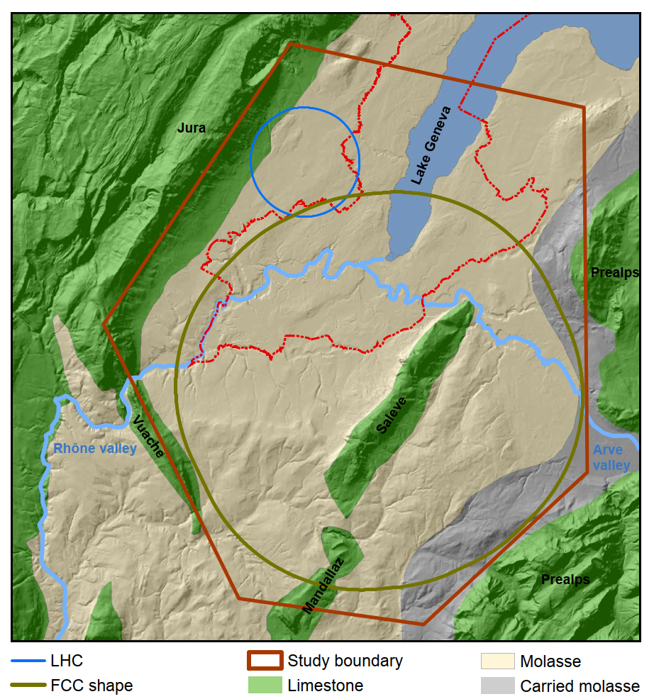
CEPC and SppC are two colliders similar to FCC-ee/FCC-hh, which are being studied by another international collaboration, centered at IHEP Beijing CEPC Study Group (2018). These two machines have almost the same circumference as the FCC, of about 100 km. Several possible locations in China are under study. The SppC hadron collider relies on 12 T (later 24 T) iron-based high-temperature superconducting magnets, which could be installed in the same tunnel as the CEPC. Table 7 compiles key parameters of the HE-LHC, FCC-hh, and SppC.
Figure 29 indicates the proposed location of the FCC in the Lake Geneva basin, connected to the existing CERN/LHC accelerator complex. The principal structure for the successively installed FCC lepton and hadron colliders (FCC-ee and FCC-hh) is a quasi-circular 97.75 km long tunnel composed of arc segments interleaved with straight sections. Approximately 8 km of bypass tunnels, 18 shafts, 14 large caverns and 12 new surface sites are also planned. The tunnel location and depth were optimized taking into account the local geology.
Collider luminosity should ideally increase with the square of the energy, since cross sections decrease as the inverse square of energy. However, due to the nonlinear parton distribution inside the colliding protons, even a lower luminosity can produce exciting physics, with the most important parameter of a hadron collider remaining its energy. Nevertheless, at a given energy the discovery reach grows with higher luminosity G.Salam and A.Weiler, Collider Reach web site — this is one of the motivations for upgrading the LHC to the HL-LHC. The LHC design has already dramatically increased luminosity compared with previous machines. Much higher luminosities still are expected for the proposed High-Energy LHC (HE-LHC) and FCC-hh, and also for the approved HL-LHC, which will lower its peak luminosity by leveling in order to make it acceptable for the physics experiments Benedikt et al. (2015). A high instantaneous luminosity would result in an event pile-up per bunch crossing of order 500 (from up to 50 in LHC), and, for the HL-LHC experiments, this could significantly degrade the quality of the particle detector data collected for the physics analysis. The technique of luminosity leveling allows sustaining the operational luminosity, and the associated event pile-up, at a constant level over a significant length of time via several techniques: (i) a gradual reduction of the beta function at the interaction point , (ii) crossing angle variation, (iii) changes in the RF voltage of crab cavities or more sophisticated crabbing schemes Fartoukh (2014), (iv) dynamic bunch-length reduction, or (v) controlled variation of the transverse separation between the two colliding beams. Of note is that the luminosity of the highest energy hadron colliders, such as HE-LHC and FCC-hh, will profit from significant radiation damping due to the associated high beam energies and magnetic fields. This radiation damping will naturally level their luminosity evolution.
Hadron-collider luminosity will increase linearly with energy due to the shrinking beam sizes , when keeping the normalized beam emittances, beam currents, the beta functions at the interaction point (IP), , and beam-beam tune shift constant. Even higher luminosity can be achieved by reducing the IP beta functions. Perhaps surprisingly, until now all hadron colliders, starting from the ISR, have operated with similar beta functions, with minimum values of about 0.3 m (see Table 6). With a value of 0.15 m (or even 0.10 m) the HL-LHC will set a new record. An ongoing study aims at pushing the FCC-hh down to 5 cm Martin et al. (2017).
For proton-proton colliders with many bunches, such as the HL-LHC and FCC-hh, a crossing angle is required to avoid or mitigate parasitic beam-beam collisions. Unfortunately, this crossing angle needs to be increased as is reduced. Without countermeasures, this would dramatically degrade the geometric overlap of the colliding bunches and all but eliminate any benefit from reducing the IP beam size. To avoid such a degradation, the HL-LHC, HE-LHC, and FCC-hh will all use novel crab cavities Verdu-Andres et al. (2016). In 2018, first beam tests of such crab cavities with protons were successfully performed at the CERN SPS Carver et al. (2019).
| collider | [m] | [m] |
|---|---|---|
| ISR | 3.0 | 0.3 |
| SS | 0.6 | 0.15 |
| HERA-p | 2.45 | 0.18 |
| RHIC | 0.50 | 0.50 |
| Tevatron | 0.28 | 0.28 |
| LHC | 0.3 | 0.3 |
| HL-LHC | 0.15 | 0.15 |
| HE-LHC | 0.25 | 0.25 |
| FCC-hh | 1.1 0.3 (0.05) | 1.1 0.3 (0.05) |
| SppC | 0.75 | 0.75 |
| HE-LHC | FCC-hh | SppC | Collider | |||
| Species | ||||||
| Beam energy (TeV) | 13.5 | 50 | 37.5 | 0.063 | 3 | 7∗ |
| Circumference (km) | 26.7 | 97.75 | 100 | 0.3 | 6 | 26.7 |
| Interaction regions | 2 (4) | 4 | 2 | 1 | 2 | 2 |
| Peak luminosity (1034 cm-2 s-1) | 15 | 530 | 10 | 0.008 | 12 | 33 |
| Int. lum. per exp. (ab-1/year) | 0.5 | 0.2–1.0 | 0.4 | 0.001 | 1.0 | 3 |
| Time between coll. () | 0.025 | 0.025 | 0.025 | 1 | 20 | 90 |
| Events per crossing | 800 | 1701000 | 300 | |||
| Energy spread (rms, ) | 0.1 | 0.1 | 0.2 | 0.04 | 1 | 1 |
| Bunch length (rms, mm) | 80 | 80 | 75.5 | 63 | 2 | 1 |
| IP beam size (m) | 6.6 | 6.8 (init.) | 6.8 (init.) | 75 | 1.5 | 0.6 |
| Injection energy (GeV) | 1300 | 3300 | 2100 | on energy | ||
| Transv. emittance (rms norm., m) | 2.5 | 2.1 (init.) | 2.4 (init.) | 200 | 25 | 25 |
| , amplitude function at IP (cm) | 45 | 11030 | 75 | 1.7 | 0.25 | 1 |
| Beam-beam tune shift / IP ( | 5 | 515 | 7.5 | 20 | 90 | 100 |
| RF frequency (MHz) | 400 | 400 | 400/200 | 805 | 805 | 805 |
| Particles per bunch ( | 22 | 10 | 15 | 400 | 200 | 200 |
| Bunches per beam | 2808 | 10600 | 10080 | 1 | 1 | 1 |
| Average beam current (mA) | 1120 | 500 | 730 | 640 | 16 | 4 |
| Length of standard cell (m) | 137 | 213 | 148 | n/a | ||
| Phase advance per cell (deg) | 90 | 90 | 90 | n/a | ||
| Peak magnetic field (T) | 16 | 16 | 12 (24) | 10 | 10 | 16 |
| SR power loss/beam (MW) | 0.1 | 2.4 | 1.2 | 0 | 0.07 | 0.5 |
| Long. damping time (h) | 3.6 | 1.1 | 2.4 | |||
| Initial burn-off time (h) | 3.0 | 173.4 | 13 | |||
| Total facility AC power (MW) | 200 | 580 | n/a | 200 | 270 | 290 |
| Novel technology | 16 T magnets | 16 T magnets | HTS magnets | prod./10-16 T magn. | ||
Future hadron colliders are characterized by record high stored beam energy, rendering machine protection a paramount concern. A very challenging multi-stage collimation system is needed to avoid local beam loss spikes near cold magnets, which would induce magnet quenches. Beam injection and beam extraction are particularly sensitive operations, as injection or dump kickers are among the fastest elements in the machine. The collider design must be robust against the sudden asynchronous firing of a kicker unit. The collimators are likely to be the first element to be hit by the beam in case of any fast failure and must be able to withstand the impact of one or a few bunches. The primary and secondary collimators of the LHC are based on carbon-carbon composite material. For the HL-LHC and future hadron colliders, ever stronger materials are being developed and examined, which also feature higher conductivity and, hence, lower “impedance”. More advanced options include the use of short bent crystals as primary collimators Scandale et al. (2016) and the deployment of hollow electron-beam lenses as non-destructible collimators Stancari et al. (2011). Acceptable performance of the collimation system, along with small IP beta function, also requires an excellent optics control.
In view of the substantial ring circumference and the associated low momentum compaction, hadron beam intensity in very large accelerators may be limited by conventional instabilities. In particular the resistive wall instability becomes a concern due the low revolution frequency, and TMCI could appear at injection due to the low synchrotron tune Burov et al. (2000); Shiltsev (2015).
For future higher-energy hadron colliders, synchrotron radiation damping becomes significant. In such a situation, longitudinal emittance needs to be kept constant during the physics store through controlled longitudinal noise excitation, in order to maintain longitudinal Landau damping F. Zimmermann (2001). At the same time, the transverse emittance shrinks due to strong radiation damping, while proton intensity rapidly decreases as a result of the “burn-off” due to the high luminosity. The initial proton burn-off time can be computed as:
| (36) |
where denotes the proton bunch population, the initial luminosity, the total proton-proton cross section, the number of bunches per beam, and the number of high-luminosity IPs; for all three colliders under consideration. The total hadron cross section grows with the c.m.e. collision energies (see Ch. 46 in Tanabashi et al. (2018)), which implies shorter beam lifetimes for higher energy hadron colliders even at a constant target luminosity and could strain requirements on the machines’ injector chains.
For the FCC-hh, the emittance damping time is shorter than the proton burn-off time. As a result, the total beam-beam tune shift increases during the store. At some point, the beam-beam limit is reached, and, from this point onward, the transverse emittance must be controlled by transverse noise excitation, so as to keep the beam-beam tuneshift at, or below, the empirical limit. This limit determines the further luminosity evolution during the store and the optimum run time Benedikt et al. (2015). By contrast, at the HE-LHC, the proton burn off time is slightly shorter than the radiation damping time. This situation is qualitatively different from that of the FCC-hh. For the HE-LHC, there is almost a natural luminosity leveling, while the beam-beam tune shift naturally decreases during the store.
The primary technology of future hadron colliders is high-field magnets, both dipoles and quadrupoles. Magnets made from Nb-Ti superconductor were the core technology of the present LHC, Tevatron, RHIC, and HERA. Nb-Ti magnets are limited to maximum fields of about 8 T. The HL-LHC will, for the first time in a collider, use some tens of dipole and quadrupole magnets with a peak field of 11–12 T, based on a new high-field magnet technology using a Nb3Sn superconductor. This will prepare the ground for the development of 16 Tesla Nb3Sn magnets, and for the later production of about 5000 Nb3Sn magnets required by the FCC-hh. The Chinese SppC magnets will utilize cables based on an iron-based high-temperature superconductor, a material discovered at the Tokyo Institute of Technology in the year 2006 Kamihara et al. (2006). Figure 30 sketches the respective current densities and field limits. It is clear that Nb3Sn can approximately double the magnetic field reached with Nb-Ti . The R&D target for SppC looks aggressive. The SppC goal is to increase magnet performance ten times while simultaneously reducing its cost by an order of magnitude. If successful, the iron-based HTS magnet technology could become a game changer for future hadron colliders.
Also important is the minimum field of SC magnets allowing for efficient operation. This minimum field is determined by balancing various considerations such as the injected beam size and magnet aperture, the magnetic field quality at injection, machine protection against accidental beam loss due to injection-system failures, beam losses, injection kicker system strength and rise time, severity of beam instabilities, overall cost, etc. Typically, the dynamic range (energy swing) of SC circular accelerators lies in the range 10–20. An increase in c.m.e. eases the beam dynamics, but implies additional acceleration stages in the injector complex, thereby potentially affecting the overall cost, the collider filling time, and the overall machine efficiency.
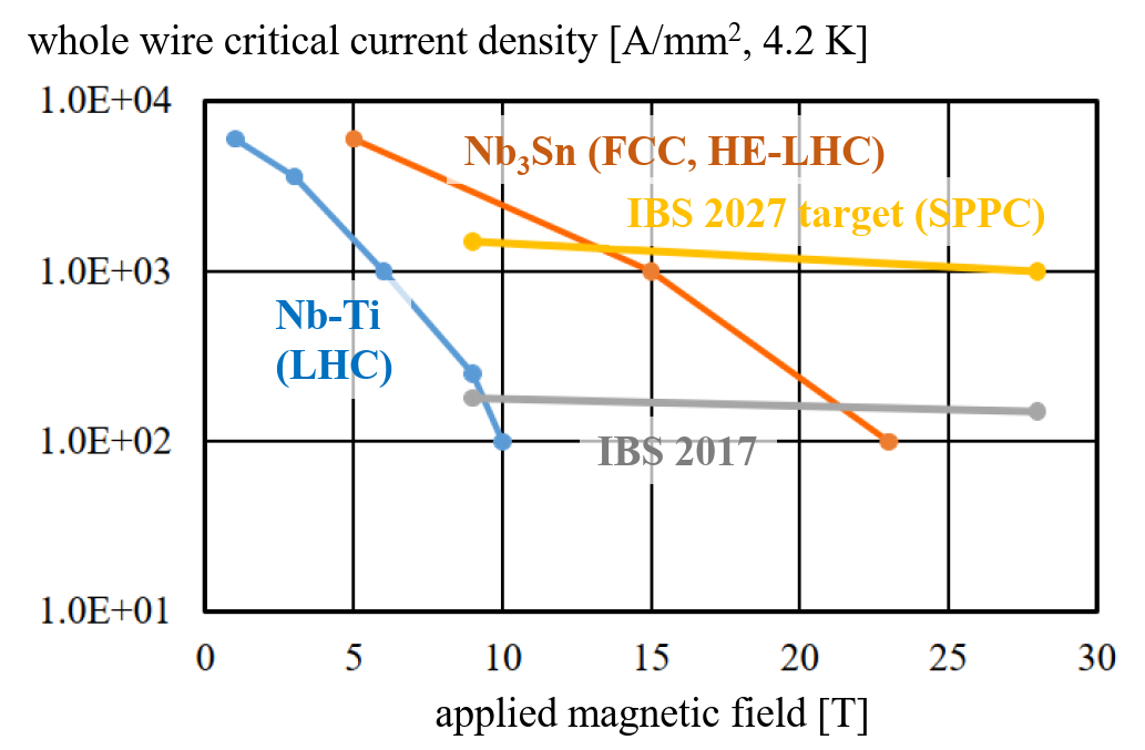
Recently, several important milestones were accomplished in the development of high-field Nb3Sn magnets. In the US, an FNAL team has completed a 15 T accelerator dipole short model demonstrator Zlobin et al. (2019). In a staged approach, as a first step this magnet was pre-stressed for a maximum field of about 14 T. In successful tests in the fall of 2019 its field indeed reached 14.1 T at 4.5 K Zlobin et al. (2020). Higher field is facilitated by a higher-quality conductor. Advanced US wires with Artificial Pinning Centers (APCs) produced by two different teams (FNAL, Hyper Tech Research Inc., and Ohio State; and NHMFL, FAMU/FSU) have reached the target critical current density for FCC, of 1500 A/mm2 at 16 T Xu et al. (2019); Balachandran et al. (2019), which is 50% higher than for the HL-LHC wires. The APCs allow for better performance; they decrease magnetization heat during field ramps, improve the magnet field quality at injection, and reduce the probability of flux jumps Xu et al. (2014).
Another important technology is the cryogenic beam vacuum system, which has to cope with unusually high levels of synchrotron radiation (about 5 MW in total for FCC-hh) in a cold environment. The design of the beamscreen intercepting the radiation inside the cold bore of the magnets and the choice of its operating temperature (50 K – significantly higher than the 5–20 K chosen for the LHC beamscreen) are key ingredients of the FCC-hh design. The first hardware prototypes for FCC-hh were tested in 2017 at the KIT ANKA/KARA facility at Karlsruhe, with synchrotron radiation from an electron beam, whose spectrum and flux resembled those of the FCC-hh. These beam measurements at ANKA/KARA validated the basic design assumptions Gonzalez et al. (2019). The latest version of the FCC-hh beamscreen design is shown in Fig. 31.
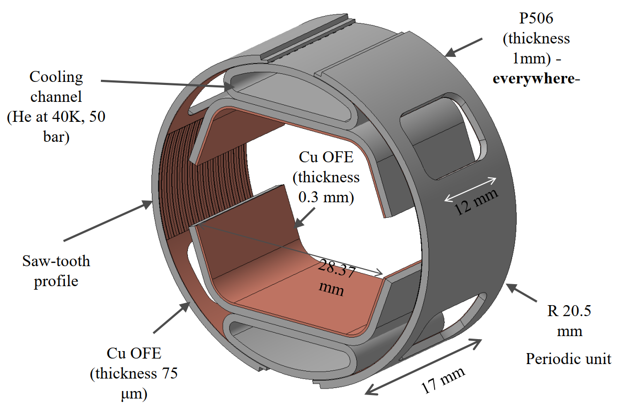
Further key technologies of energy frontier hadron colliders include the collimators, the kicker and septa required for the extremely high beam energy, and the SC RF systems, e.g., for acceleration and for compensation of synchrotron-radiation energy losses, as well as for ever more demanding crab cavities.
The tunnel is a core element of any new collider. The FCC-hh (FCC-ee) and SppC (CEPC) tunnels are to be constructed differently, by tunnel boring machines and drill/blast techniques, respectively. The tunnel shapes and sizes are also rather different, as is illustrated in Fig. 32. The HE-LHC must fit into the existing LHC tunnel, with a diameter of 3.8 m. The HE-LHC dipole magnets must, therefore, be made as compact as possible, with a maximum outer diameter of 1.2 m. In addition, half-sector cooling is proposed to reduce the diameter of the cryogenics lines and relax tunnel integration, calling for additional 1.8 K refrigeration units. The new round tunnel for the FCC-hh will have a significantly larger diameter of 5.5 m, to host the (possibly larger) 16 T magnets and enlarged cryogenics lines, plus allow for additional safety features, such as smoke extraction, ventilation, and escape passages. This large a tunnel still does not offer enough space to accommodate both a lepton and a hadron machine at the same time. If the FCC-ee is built as a first step, it will need to be disassembled prior to the installation of the FCC-hh hadron collider. The SppC tunnel is even larger, with a transverse width of 8.7 m. It is meant to provide enough space for both lepton and hadron machines, also including a lepton booster ring for top-up injection, which, in principle, could all be operated in parallel.
The HE-LHC cryogenic system reuses the existing LHC helium refrigerators, which will be upgraded by doubling the number of 1.8 K refrigeration units (2 units per sector instead of 1 unit) and by adding specific refrigeration units for temperatures above 40 K to handle, in particular, the beam-induced heat load on the beamscreens, which is dominated by the synchrotron radiation power of about 190 kW. It should be noted that by 2040, some of the existing LHC cryoplants will be 50 years old, and that the associated ageing issues need to be carefully studied. In view of their much larger circumference and very high synchrotron radiation power, the FCC-hh and SppC will both still need substantially larger cryogenic facilities. Specifically, the FCC-hh foresees 10 cryoplants, each with 50–100 kW at 4.5 K including 12 kW at 1.8 K, and requiring a helium inventory of 800 tons, about 6 times the helium inventory of the present LHC. The FCC-hh will use a cryogenics system based on a neon-helium mixture (nelium), which leads to electrical energy savings of about 10% with respect to the LHC-type helium cryogenics infrastructure The electrical power consumption of the FCC-hh cryoplants is about 200 MW L. Tavian (2017).

To summarize, the key challenges for the energy frontier colliders such as the HE-LHC, FCC-hh, and SppC are associated with the need for long tunnels (27 km, 100 km and 100 km, respectively), high field SC magnets (16 T, 16 T and 12 T, respectively), and total AC site wall plug power ranging from about 200 MW (HE-LHC) to 500 MW. The cost estimates extend from 7.2 BCHF for the HE-LHC to 17.1 BCHF for the FCC-hh (assuming that the 7 BCHF tunnel is available) — see Table 7. In all these options, the detectors will need to operate at luminosities of cm-2s-1) and the corresponding pile-up of events per crossing will be (500). A 12–18 year long R&D program is foreseen to address the most critical technical issues, such as: (i) development of accelerator quality 16 T dipole magnets based on Nb3Sn (or 12 T iron-based HTS magnets for the SppC); (ii) effective intercept of synchrotron radiation (5 MW in FCC-hh and 1 MW in SppC); (iii) beam halo collimation with circulating beam power 7 times that of the LHC; (iv) choice of optimal injector (e.g., a new 1.3 TeV SC SPS, or 3.3 TeV ring either in the LHC tunnel or the FCC tunnel, for the FCC-hh), and (v) overall machine design issues (IRs, pile-up, vacuum, etc), power and cost reduction, etc. It is noteworthy that such machines can additionally be used for ion-ion/ion-proton collisions; high energy proton beams can also be collided with high intensity (60) GeV electrons from an ERL.
IV.3.2 Muon colliders
The lifetime of the muon, 2.2 s in the muon rest frame, is sufficient to allow fast acceleration to high energy before the muon decays into an electron, a muon-type neutrino, and an electron-type antineutrino () and storage for some 300 turns in a ring with average field (Tesla). The muon to electron mass ratio of 207 implies that all synchrotron radiation effects are smaller by a factor of about . Even a multi-TeV collider can be highly power efficient, while being circular, and, therefore, may have quite a compact geometry, that will fit on existing accelerator sites or tunnels. The c.m.e. spread for 3 to 14 TeV colliders is (see parameters of such facilities in Table 7), which is an order of magnitude smaller than for an collider of the same energy. Much like in colliders, the muon collider center of mass energy is entirely available to produce short-distance reactions rather than being spread among proton constituents. A 14 TeV muon collider with sufficient luminosity might be very effective as a direct exploration machine, with a physics potential similar to that of a 100 TeV proton-proton collider — see Fig. 33 from Ref. Delahaye et al. (2019).
In general, muon colliders are predicted to be significantly less expensive than other energy frontier hadron or machines Shiltsev (2014). They need lower AC wall plug power Delahaye (2018); Boscolo et al. (2019) and, due to compact size, a smaller number of elements requiring high reliability and individual control for effective operation Shiltsev (2010b). In addition, a Higgs factory would have the advantages of a large Higgs production cross-section via -channel production, and of a beam energy equal to about one half of the standard Higgs production mode at 240–250 GeV c.m.e. (i.e., 263 GeV for ). It would, therefore, offer a small footprint, a low energy spread in non-radiating muon beams, (3 MeV), and low total site power of 200 MW Ankenbrandt et al. (1999); Alexahin et al. (2018). Finally, a neutrino factory could potentially be realized during the course of its construction Geer (1998, 2009); Boscolo et al. (2019).
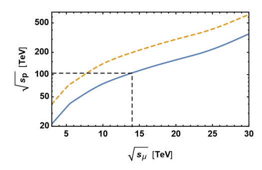
Muon colliders were proposed by F. Tikhonin and G. Budker at the end of the 1960s Tikhonin (1968); G.I.Budker (1970a, b) and conceptually developed later by a number of authors and collaborations (see a comprehensive list of references in Refs. Geer (2009); Boscolo et al. (2019)). Figure 34 presents a possible layout of a multi-TeV c.m.e. high luminosity ( cm-2s-1) muon collider, consisting of: (i) a high power proton driver (SRF 8 GeV 2–4 MW linac); (ii) pre-target accumulation and compressor rings, in which high-intensity 1–3 ns long proton bunches are formed; (iii) a liquid mercury target for converting the proton beam into a tertiary muon beam with energy of about 200 MeV; (iv) a multi-stage ionization cooling section that reduces the transverse and longitudinal emittances and, thereby, creates a low emittance beam; (v) a multistage acceleration (initial and main) system — the latter employing recirculating linear accelerators (RLA) to accelerate muons in a modest number of turns up to 2 TeV using superconducting RF technology; and, finally, (vi) a roughly 2 km diameter collider ring located some 100 m underground, where counter-propagating muon beams are stored and collide over the roughly 1000–2000 turns corresponding to the muon lifetime.
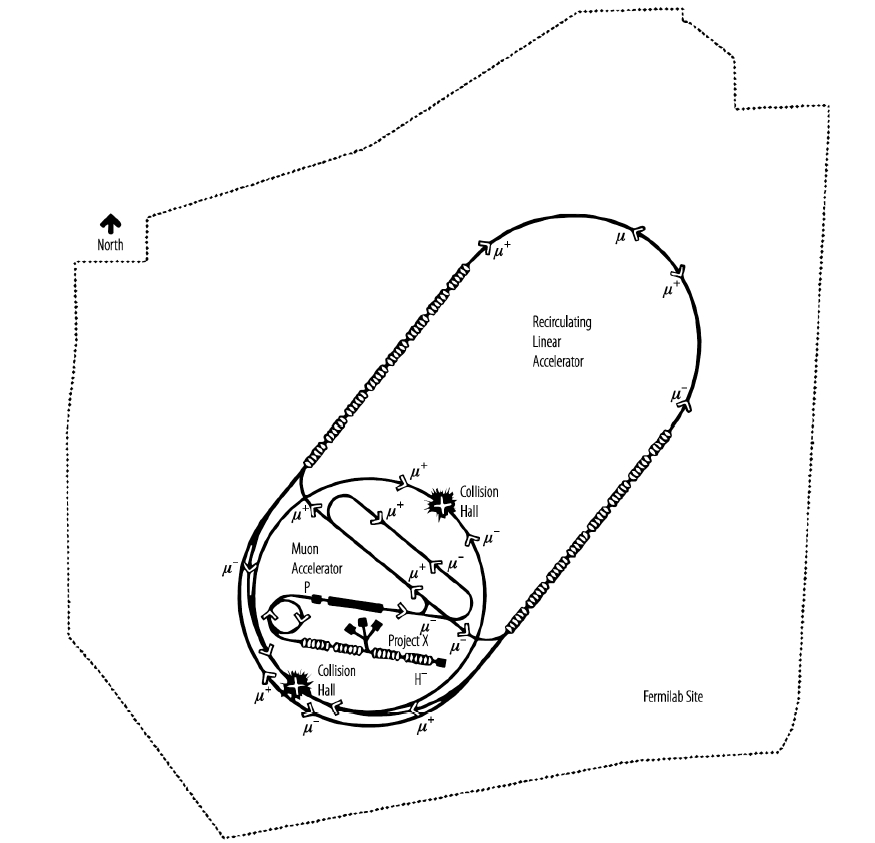
Since muons decay quickly, large numbers of them must be produced to operate a muon collider at high luminosity. Collection of muons from the decay of pions produced in proton-nucleus interactions results in a large initial 6D phase-space volume for the muons, which must be reduced (cooled) by a factor of 106 for a practical collider. Without such cooling, the luminosity reach will not exceed ( cm-2s-1). The technique of ionization cooling proposed in Ado and Balbekov (1971); Skrinsky and Parkhomchuk (1981); Neuffer (1983) is very fast and uniquely applicable to muons because of their minimal interaction with matter. It involves passing the muon beam through some material absorber in which the particles lose momentum essentially along the direction of motion via ionization energy loss, commonly referred to as . Both transverse and longitudinal momentum are reduced via this mechanism, but only longitudinal momentum is then restored by reacceleration, leaving a net loss of transverse momentum (transverse cooling). The process is repeated many times to achieve a large cooling factor.
The rate of change of the normalized transverse emittance as the beam passes through an absorber is given approximately by
| (37) |
where denotes the muon velocity, the muon energy, the mean energy loss per unit path length, the radiation length of the absorber, and the transverse betatron function at the absorber. The first term of this equation describes the cooling effect by ionization energy loss and the second describes the heating caused by multiple Coulomb scattering. Initially the cooling effect dominates over the heating one, leading to a small equilibrium emittance. The energy spread acquired in such a process due to fluctuation of ionization losses (Landau straggling) can be reduced by introducing a transverse variation in the absorber density or thickness (e.g., a wedge) at a location where there is dispersion (a correlation between transverse position and energy). This method results in a corresponding increase of transverse phase space, represents an exchange of longitudinal and transverse emittances, and allows cooling in all dimensions, thanks to the fast transverse cooling Palmer (2014).
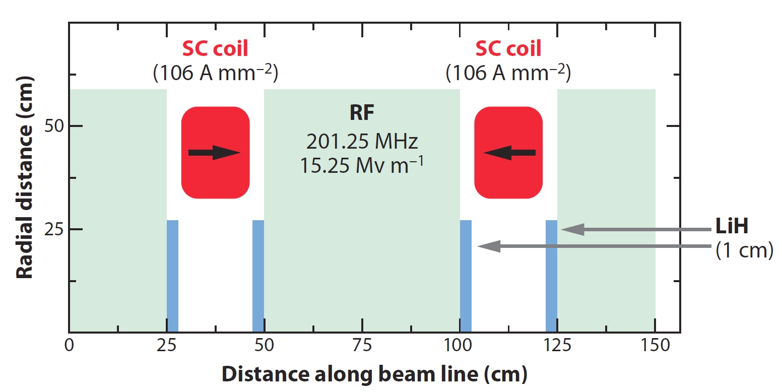
Theoretical studies Palmer et al. (1996); Sessler (1998) and numerical simulations Sayed et al. (2015) have shown that, assuming realistic parameters for cooling hardware, ionization cooling can be expected to reduce the phase space volume occupied by the initial muon beam by a factor of 105 to 106. A complete cooling channel would consist of 20 to 30 cooling stages, each yielding about a factor of 2 in 6D phase space reduction; see Fig. 35.
The ionization cooling method, though relatively straightforward in principle, faces some practical implementation challenges. These include RF breakdown suppression and attainment of high accelerating gradients in relatively low frequency NC RF cavities immersed in strong magnetic fields. The International Muon Ionization Cooling Experiment (MICE) Sandstrom et al. (2008); Adams et al. (2019) at RAL (UK) has recently demonstrated effective (10%) reduction of transverse emittance of initially dispersed 140 MeV/c muons passing through an ionization cooling channel cell consisting of a sequence of LiH or liquid hydrogen absorbers within a lattice of up to 3.5 T solenoids that provide the required particle focusing Mohayai (2018); Bogomilov et al. (2020).
Constructing and operating a muon collider with usable luminosity requires surmounting significant technical challenges associated with the production, capture, cooling, acceleration, and storage of muons in large quantities and with appropriate phase-space densities. References Palmer (2014); Boscolo et al. (2019) provide comprehensive overviews of the significant progress achieved in developing the concepts and technologies needed for high luminosity energy frontier muon colliders. Beside the pioneering demonstration of ionization cooling by MICE, muon collider R&D has led to a number of remarkable advances in the past decade. The Mercury Intense Target experiment (MERIT) McDonald et al. (2009) has successfully injected a high intensity proton beam from the CERN proton synchrotron into a liquid mercury jet inside a 15 T solenoid, proving the feasibility of beam power in excess of 4 MW on such targets. Accelerating gradients of 50 MV/m were obtained in vacuum and pressurized gas-filled NC RF immersed in a 3 T magnetic field at Fermilab Bowring et al. (2018); Chung et al. (2013). Also at Fermilab, rapid cycling HTS magnets achieved a record field ramping rate of 12 T/s Piekarz et al. (2019). The first RF acceleration of muons was demonstrated at the JPARC MUSE RFQ Bae et al. (2018). Some 16–20 T small bore HTS solenoids were built at BNL — an important step toward the 30–40 T magnets needed for the final muon cooling stage Gupta et al. (2013). The US Muon Accelerator Program collaboration and its international partners have successfully carried out complete 6D muon ionization cooling simulations — see Fig. 36 — as well as overall facility feasibility studies, demonstrating that muon colliders can be built with present-day SC magnet and RF technologies, and developed initial designs for 1.5 TeV, 3 TeV, 6 TeV, and 14 TeV colliders (see Table 7).
A novel concept is being proposed of using 45 GeV positrons to generate muon pairs through annihilation just above threshold Antonelli et al. (2016), allowing low emittance beams to be obtained directly, without any cooling. This scheme may allow operation of a very high energy muon collider with manageable neutrino radiation on and off the site. Major directions of the R&D to evaluate the possible luminosity reach of this concept and to address key issues of corresponding technologies have been outlined in Boscolo et al. (2019).
Another novel approach, called the Gamma Factory (GF) Krasny (2015); Krasny et al. (2018), could potentially help make a muon collider become reality. The GF would generate frequent bursts of gamma rays by repeatedly colliding a partially stripped heavy-ion beam circulating in the LHC, or in a future higher-energy hadron storage ring like the FCC-hh, with a conventional laser pulse, profiting from two Lorentz boosts. Impinging on a suitable target, the GF’s intense gamma bursts could produce positrons or muons at an unprecedented rate. Thereby, the GF could deliver positrons at the rate required for the aforementioned positron-based muon production, or, alternatively, it could directly provide a low-emittance muon beam Zimmermann (2018). In 2018, first beam tests confirmed the predicted long beam lifetime, of more than a day, for a partially-stripped heavy-ion beam stored in the LHC at top energy Schaumann et al. (2019). The next series of proof-of-principle GF experiments, consisting of laser-beam collisions in the SPS, is planned for 2021.
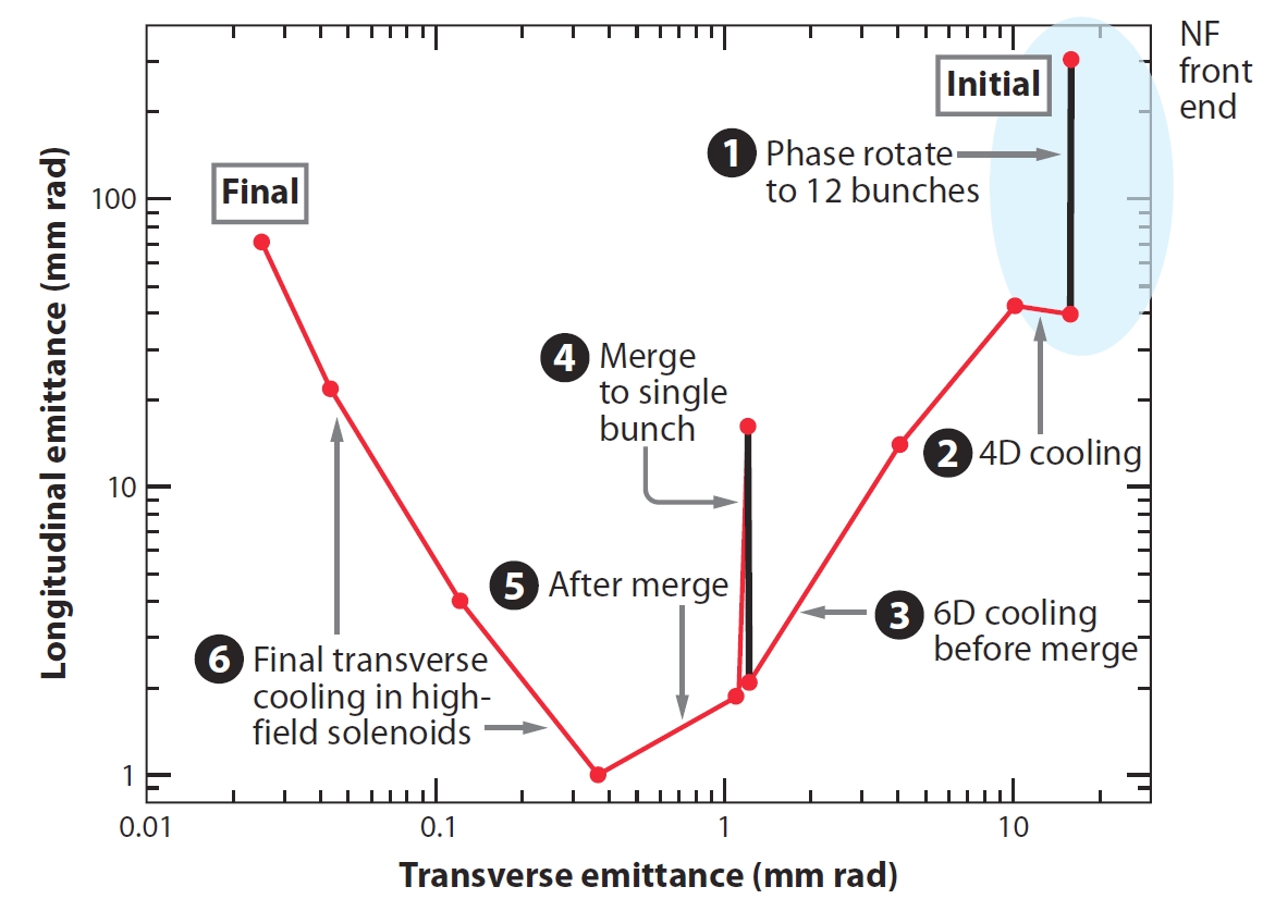
Under active study are concepts for muon collider detectors which must operate in the presence of various backgrounds originating from muon decay and effective measures to control neutrino radiation Bartosik et al. (2019). Any straight section within the collider ring produces a beam of muon-decay neutrinos in the direction of the straight section. These neutrinos exit the Earth at some point, perhaps a few tens of kilometers away if the ring is deep. At the exit point, neutrino interactions within the rock create radiation at the surface. The radiation level increases rapidly with the stored muon energy. Besides the straightforward approach of placing the collider ring tunnel at sufficient depth, there are several mitigation ideas on how to keep neutrino radiation below the commonly accepted limit of 1 mSv/yr. E.g., the radiation density can be reduced by about an order of magnitude by adding a vertical collider orbit variation of a few mm.
V Advanced collider concepts
V.1 Acceleration in plasma and plasma-based collider proposals
Since about the mid-1950s, it has been understood that collective plasma-based accelerators offer the great promise of extremely large accelerating gradients Veksler (1957). Ionized plasmas can sustain electron plasma density waves with electric fields in excess of or
| (38) |
(so-called cold nonrelativistic wave-breaking field Dawson (1959)) where denotes the ambient electron number density, the electron plasma frequency, and electron rest mass and charge, respectively, the speed of light in vacuum, and the electrical permittivity of free space. For example, a plasma density of about 1018 cm-3 yields 100 GV/m, approximately three orders of magnitude greater than 100 MV/m obtained in conventional breakdown limited RF structures.
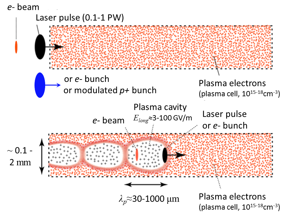
Such gradients can be effectively excited by either powerful external pulses of laser light or by electron bunches if they are shorter than the plasma wavelength mm, or by longer beams of charged particles if their charge density is modulated with the period of . Figure 37 illustrates the concept of plasma acceleration. For example, the plasma response to a short laser pulse is as follows Tajima and Dawson (1979): (i) the laser pulse enters the plasma and transversely accelerates plasma electrons (ponderomotive force as transverse driving force), (ii) the plasma ions move a negligible amount and a positively charged ion channel is formed along the laser path, (iii) after the passage of the laser pulse, the plasma electrons rush back in, attracted by the transverse restoring force of the positively charged ion channel, pass the center of the ion channel, rush back out and are attracted back by the ion channel, and (vi) a space charge driven oscillation is formed, leaving alternating regions of negative and positive net charge with strong induced longitudinal fields behind the laser pulse (plasma wakefields). If a short test bunch of charged particles, e.g., electrons, is placed behind the laser pulse at a proper distance, then it will be accelerated with high gradient. The process could be limited by depletion of laser pulse power, dephasing between the relativistic test bunch and the wakefield, and the Rayleigh length of the laser beam (unless counteracted by self-guiding or external guiding of the laser in a plasma channel). Similar concepts have been proposed for plasma wakefields driven by short electron bunches Chen et al. (1985) and by self-modulated high energy proton bunches with an rms bunch length of order 10 cm Caldwell et al. (2009).
The three plasma driver technologies have been explored theoretically and experimentally, and corresponding reviews and references can be found in Esarey et al. (2009); Hogan (2016); Adli and Muggli (2016). In the past decade, we have seen impressive progress of the plasma wakefield acceleration of high quality beams. Laser driven electron energy gain of about 8 GeV over 20 cm of plasma with density 31017cm-3 has been demonstrated at the BELLA facility at the Lawrence Berkeley National Laboratory (LBNL) Gonsalves et al. (2019). Short electron bunches were used to boost the energy of externally injected electron bunches by 9 GeV over 1.3 m of 1017cm-3 plasma at the FACET facility in SLAC Litos et al. (2016) — see Fig. 38. The AWAKE experiment at CERN used self-modulating long 450 GeV proton bunches to accelerate electrons to 2 GeV over 10 m of 1015 cm-3 plasma Adli et al. (2018).
In principle, the plasma wakefield acceleration scheme has the potential to be staged, e.g., several plasma cells of the same kind can be placed in series, resulting in potentially higher beam energy. That makes possible attainment of very high energies and designs of TeV or multi-TeV colliders, such as proposed in Refs. Leemans and Esarey (2009); Schroeder et al. (2010); Adli et al. (2013). The primary advantage that a plasma wakefield accelerator could present is a considerably greater compactness and, hence, a much lower ‘real-estate’ investment for the collider. There are a number of critical issues that need to be resolved along that path Assmann and Grebenyuk (2014); Lebedev et al. (2016); Schulte (2016) including acceleration of positrons (which are defocused by the positively charged ion cavity when accelerated in a plasma — see Fig. 37), instabilities in accelerated beams and beam emittance control in scattering media, final focusing of and bunches with significant energy spread acquired during acceleration, and efficiency of staging (beam transfer and matching from one (1m) long plasma cell to another). Indeed, strong transverse focusing gradients (10MT/m) are generated inside the ion channel of plasma accelerators. Such focusing is equivalent to very small beta functions in the range of a couple of cm to a few mm for high energy beams accelerated in the cm-3 plasma. Matching electrons and positrons in and out of these multiple plasma cells is difficult and compared to “low-” insertions of traditional colliders, transverse injection error tolerances (1m) become highly demanding.
Comparative analysis of initial strawman designs of high luminosity 3 TeV to 10 TeV to 30 TeV laser-driven and beam-driven colliders Input 7 to the European Particle Physics Strategy Update Open Symposium () (Granada, Spain, 2019); Adli et al. (2013) with that of CLIC does not show significant AC-to-beam-power efficiency advantage of the advanced schemes; AC wall plug power needs are 0.5 GW for 10 TeV c.m.e. and over 1 GW for 30 TeV c.m.e. machines. The total facility length will still be considerable (6 to 8 km for =3 TeV, 10–18 km for 10 TeV) and the beamstrahlung effect will ultimately be severe — the expected rms energy spread at the IP is about 30% for 10 TeV machines and 80% for 30 TeV colliders.
Reference Caldwell and Wing (2016) proposes an LHC upgrade for a very high energy 9 TeV c.m.e. electron–proton collider using a 3 TeV electron beam accelerated by the proton driven plasma wakefields. In this scenario, one of the two 7 TeV LHC proton beams is used as the proton driver to create plasma wakefields accelerating electrons to 3 TeV, which then collide with the other 7 TeV LHC proton beam. Assumed are 3000 LHC bunches per fill with a 30 min machine cycle time, 1011 electrons and protons per bunch (about twice the value foreseen for the LHC luminosity upgrade), as well as a transverse RMS beam size of 4 m, to reach a relatively low luminosity of cm-2s-1.
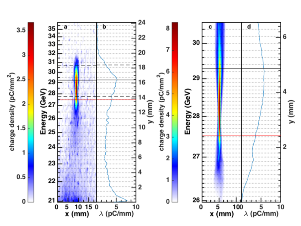
Plasma wakefield acceleration concepts have not yet achieved the level of a reliable conceptual design for an affordable high luminosity multi-TeV collider. The ILC and CLIC studies have emphasized that the performance reach of a linear collider is essentially proportional to the beam power and at present the plasma wake-field acceleration technology is far from the wall-plug efficiency of NC and SRF linacs. Correspondingly, the focus of the current R&D activities carried out by several groups and collaborations Input 7 to the European Particle Physics Strategy Update Open Symposium () (Granada, Spain, 2019), including EuPRAXIA (European Plasma Research Accelerator with eXcellence In Applications) Walker et al. (2017) and ALEGRO (the Advanced LinEar collider study GROup) Muggli and Cros (2018), is less on breaking the accelerating gradient records and more on mundane, but critical issues such as energy transfer efficiency, production of high quality high repetition rate beams with the various driver technologies, positron acceleration, staging, and exploration of the possibilities offered by recent advances in high peak power laser technologies (similar to how chirp pulse amplification boosted the laser plasma acceleration technique Mourou (2019), awarded with the 2018 Nobel Prize in Physics). A number of beam test facilities addressing these major scientific challenges are either operating, coming on-line, or in the planning phase. In the US, roadmaps of advanced accelerator R&D have been developed with the primary long-term goal of a technical design report (TDR) of a multi-TeV collider in the 2035–40 time period and a secondary, nearer-term goal of the completion of a TDR for potential early application of these acceleration techniques in the 2025–30 time period Colby and Len (2016).
V.2 Other advanced approaches for colliding beam schemes
In addition to the designs and concepts presented above, many ideas and approaches have been proposed to extend the energy reach of future particle colliders, reduce their cost, and improve their luminosity and energy efficiency. Below we present some which have shown promise and have been considered in at least some detail for applications in future nuclear physics or particle physics colliders.
Economical magnets for very large hadron colliders. The potential benefits of using modest or relatively low field magnets to reach ultra-high proton beam energies in extremely large circular colliders were first discussed by E. Fermi who in the mid-1950s thought of an Earth-encircling “Globaltron” with circumference of =40,000 km and energy reach of 5000 TeV (5 PeV) Cronin (2004). Attempts to figure out a cost-feasible variation of such a concept include the “Collider in the Sea” (=1,900 km, underwater in the Gulf of Mexico, =500 TeV with economical 3.2 T SC magnets) McIntyre et al. (2016), the 300 km circumference 300 TeV “Eloisatron” with 10 T magnets Zichichi (1990); Barletta (1996), and the 233 km long Very Large Hadron Collider (VLHC) Ambrosio et al. (2001). In the VLHC design, the Stage 1 machine was to accelerate 20 TeV proton beams in a 2 T double-aperture superferric SC magnet synchrotron ring and collide them at =40 TeV. Afterwards, the Stage 1 complex would act as an injector accelerator to a 200 TeV c.m.e. collider in the same tunnel based on 12 Tesla Nb3Sn magnets. A 1.5 m long single turn 100 kA SC transmission line twin-aperture combined function dipole magnet prototype for the VLHC Stage 1 has been built at Fermilab and demonstrated good field quality at the design 2 Tesla field Piekarz et al. (2006). Opportunities to reduce the cost of the 100 km FCC-hh collider by using 6 T to 8 T economical NbTi SC magnets — resulting in =37.5–50 TeV — are also being discussed. As mentioned above, in China, prospects of having inexpensive 12–24 T iron-based HTS superconductors have initiated machine design studies of the Super proton-proton Collider (SppC) in the 100 km CEPC tunnel Tang (2017); Benedikt and Zimmermann (2018).
Energy recovery linacs (ERLs). Another promising and actively developing technology is that of recirculating linear accelerators (RLAs) and energy recovery linacs (ERLs). RLAs are accelerators in which the accelerating structure of an RF linac is used multiple (a few to dozens of) times to accelerate the same beam. Return beamlines that are needed to take the beam out of the linac and to reinject it back at proper phase tend to be much cheaper to build than additional RF linac length, thus offering a cost–effective option to achieve the highest possible energy from a given RF installation. Such a hybrid arrangement of linac and ring also allows superior electron beam quality compared to a storage ring. Indeed, the beam dwells a short time in the accelerator and avoids many storage ring processes leading to emittance growth (due to, e.g., synchrotron radiation) or depolarization. With proper care for beam dynamics, electron beam brightness is then determined by the electron source and can thus be high Merminga et al. (2003); Ben-Zvi (2016), (Myers and Brüning, 2016, Ch.39). In instances where high average current is required, as for high luminosity colliders, the RLA concept can be augmented with a reverse process of energy recovery: the energy invested in accelerating a beam is returned to the device powering the acceleration by decelerating the beam after it has been put to some use. The basic principle of the energy recovery process is illustrated in Fig. 39.
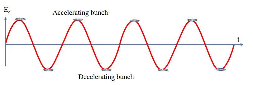
The original idea of an SRF ERL is due to Tigner Tigner (1965), but only in the past two decades has the SRF technology matured enough to render the full potential of ERLs accessible Liepe and Knobloch (2006). Superconducting RF cavities allow efficient operation in either CW (continuous wave) or in a long pulse regime (due to very high quality factor )). Thanks to lower frequency and high gradients, which can potentially exceed 50 MV/m Grassellino et al. (2018), they offer larger stored energy compared to NC RF structures and lower beam impedances, which could excite detrimental instabilities at high beam current. Envisioned SRF ERL applications include accelerators for the production of synchrotron radiation and free electron lasers Gruner et al. (2002), high-energy electron cooling devices, and ion colliders Ben-Zvi (2016).
ERL applications for the JLEIC electron cooling system and in the LHeC and FCC-eh electron-proton colliders are presented above in Sec. 4. An alternative option of an ERL-based eRHIC design was studied in sufficient detail and summarized in the CDR document Aschenauer et al. (2014). The 10 mA polarizied ERL in the RHIC tunnel needs 12 passes through a 1.32 GeV SRF linac to produce 15.9 GeV polarized electrons which are then collided with 250 GeV protons with high luminosity of order cm-2s-1. The major challenges of such an approach include: a) the need to suppress excitation of high order modes (HOMs) by the beam passing the ERLs SRF cavities to avoid current-limiting beam break up instability; b) generation of high average current of polarized electron beam out of an RF gun; c) halo and beam loss control in the ERL to avoid undue heating and potential damage; d) collective effects due to coherent synchrotron radiation and space-charge effects; e) precise magnetic field quality control in numerous return beamlines of the ERL and f) eRHIC design specific coherent electron cooling scheme for hadron beams Litvinenko and Derbenev (2009). In 2019, a demonstrator facility, the Cornell-BNL ERL Test Accelerator (CBETA), has accelerated electrons from initial 6 MeV to 42, 78, 114, and 150 MeV in four passes through the SRF cavities and subsequently decelerated them during four additional passes through the same cavities back to their original 6 MeV energy BNL Newsroom: Transformative ‘Green’ Accelerator Achieves World’s First 8-pass Full Energy Recovery . CBETA was also the first accelerator to use a single beamline with fixed magnetic fields to transport seven different accelerating and decelerating energy beams Michnoff et al. (2019).
ERL-based Higgs factories and colliders. A similar concept was also proposed as an option for the FCC-ee ring collider in a 100 km tunnel in which two 33.7 GeV linacs would accelerate and beams in four passes to =250 GeV needed for Higgs boson physics research Litvinenko et al. (2019). Flat electron and positron beams with emittances two orders of magnitude smaller than those in the ring-ring FCC-ee design (see Ch. IV.2 and Table 5) would be generated in 2 GeV cooling rings with top-up injection, then extracted out of the rings with the frequency required by the collider and accelerated to collision energy in a 4 to 6 pass ERL bypassing the interaction regions. Each path requires an individual 100 km arc made of either permanent magnets or low-cost, very low power consumption 0.04 T electromagnets. As the top energy beams collide at the IPs, their phases are changed to deceleration and they return up to 81% of the energy back into the SRF cavities. Some 14 GeV of beam energy will be lost to synchrotron radiation in the arcs, but given that the total required beam current is very small, total SR power losses will be an order of magnitude lower than in the FCC-ee design, i.e., only 10 MW for a design luminosity of few cm-2s-1. Low average current would render the ERL relatively free of HOMs and coherent instability concerns, but preservation of the ultra-small beam emittances over hundreds of km of beamlines might be as challenging as for linear colliders.

The idea of a photon–photon collider through near-IP conversion of high energy electron beams into intense beams by backward Compton scattering of a high power laser was put forward in the early 1980s Ginzburg et al. (1981). The spectrum of resulting s will be close to the incident electron energy, so with a proper laser system, such a scheme (see Fig. 40), can obtain and collisions with energy and luminosity comparable to electron-position luminosity, will be free of the beamstrahlung effect, and would not need a positron beam production complex Telnov (1995). An additional advantage for Higgs physics studies is that the energy of photons has to be only half of the for the -channel production reaction , i.e., about 62.5 GeV, requiring lower initial electron beam energy of only 80 GeV vs =125 GeV in the collider Higgs factory designs. Besides elimination of the positron production system and reduced electron energy, ERL-based concepts for facilities that could reach the Higgs mass in collisions offer additional opportunities to minimize accelerator costs by using a flat beam electron gun instead of electron damping rings and minimizing the total required accelerating voltage of RF sections Gronberg (2014); Bogacz et al. (2012). In order to lower beam energy losses due to synchrotron radiation in the ERL arcs, such Higgs factories should be placed in longer circumference tunnels. Two examples are the HFiTT proposal to employ a total of 10 GeV of SRF accelerators in the existing 6.3 km circumference Tevatron tunnel at Fermilab Chou et al. (2013) and the SAPPHiRE proposal with 22 GeV of SRF linacs in the 9 km long racetrack tunnel Bogacz et al. (2012). Of concern for such machines is the problem of emittance dilution due to synchrotron radiation and other effects in their very long arcs Telnov (2014). The pulse structure of the ERL based Higgs factories with short distance between collisions is very well suited for fiber lasers, and breakthroughs in coherent amplification of short pulses in such lasers Mourou et al. (2013) may eventually spark serious interest in the colliders Takahashi (2019).
“Cold” normal–conducting RF. The concept of a TeV-class linear collider based on NC copper accelerating cavities operating at liquid nitrogen temperature offers promise of significantly lower linac cost and power per GeV than in the ILC (SRF cavities at 2 K) and CLIC (room temperature RF structures) Bane et al. (2018). The linac design is based on two features: a 5.7 GHz accelerator structure with a separate feed to each cavity permitting the iris to be optimized for high gradient 117 MV/m and lower breakdown rate, and linac RF operation at 77 K, causing Cu (or Cu alloy) conductivity to increase and reducing RF power requirements by about a factor of 2.5. Preliminary design studies indicate some 342 MW of total AC power would be needed for a 2 TeV c.m.e. collider with luminosity cm-2s-1.
Dielectric Wakefield Accelerators (DWFA). Substantial research efforts have been carried out to extend the two-beam acceleration scheme (similar to that of CLIC) in which resonant dielectric accelerating structures are fed by ultra-short RF pulses of wakefields driven by either collinear or preceding high charge electron bunches Gai et al. (1988); Gai (2009); Jing (2016). In the latter case, electromagnetic power is radiated by an ultrashort, intense “driving” electron bunch propagating in a high impedance environment, and then used to accelerate another “witness” bunch. Better breakdown properties of some dielectric materials (quartz, ceramics, diamond) and improvement of the BDR with shorter RF pulse length (see Eq. (34)) allow gradients in excess of 1 GV/m for ps exposure times, as demonstrated with simple (0.1 mm) diameter hollow dielectric tubes driven by short, narrow and intense 28.5 GeV SLAC linac bunches Thompson et al. (2008). For collider applications, much longer pulses are needed to drive many bunches and attain high average currents. For example, in the 3 TeV c.m.e. Argonne Flexible Linear Collider proposal Gai et al. (2012), some 20 ns long 26 GHz RF pulses (12 times shorter than in CLIC) are generated by 32 50 nC drive beam bunches out of 0.86 GeV 1.3 GHz RF linacs passing through decelerating structures. This scenario should allow 270 MV/m operational accelerating gradients for the main beams. To date the beam accelerating gradient achieved in 26 GHz alumina structures is about 30 MV/m (1.8 MeV acceleration over 6.5 cm) and some 70 MV/m in 11.7 GHz structures (4.9 MeV over 7 cm) Shao et al. (2018). Application of this concept to colliding beams faces many challenges, such as fabrication of efficient dielectric high gradient RF structures, drive beam production with bunch charge an order of magnitude greater than typically achieved in the most common efficient RF guns, and wakefield damping to assure main beam stability and attainment of overall AC power to beam efficiency comparable or exceeding that of CLIC Schulte (2016); Jing (2016). Design, construction and testing of a smaller module for free electron laser (FEL) applications Zholents et al. (2016) may greatly help to advance DWFA technology.
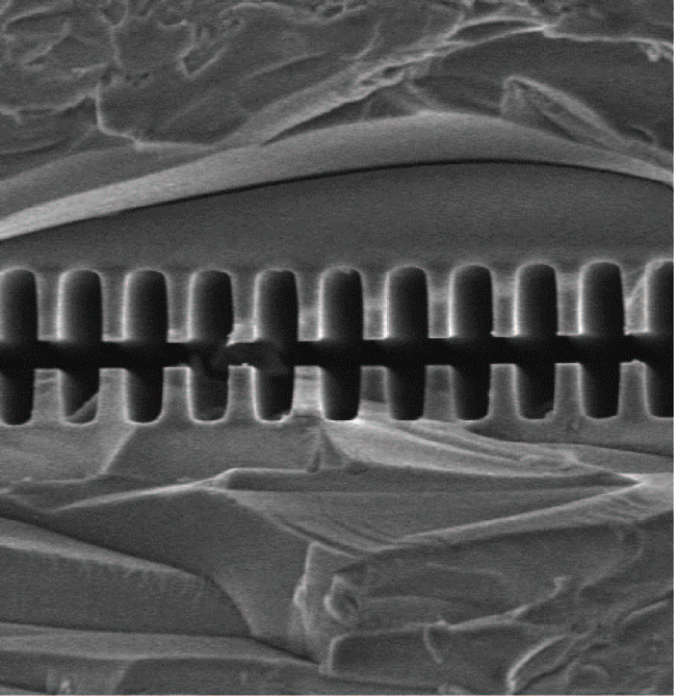
Dielectric Laser Accelerators (DLA). Micron-size dielectric accelerating structures can be driven not by conventional RF, but rather by a laser Peralta et al. (2013), and they can support accelerating fields an order of magnitude higher than can RF cavity-based accelerators. For example, some 35 keV electron energy gain over only 50 microns (700 MV/m gradient) was achieved in a fused silica DLA structure with 800 nm grating period driven by a 90 fs 800nm Ti:sapphire laser pulse Wootton et al. (2016). Despite relatively modest accelerating gradients as compared with plasmas, the prospects of using commercial lasers as a power source, which are smaller and less expensive than the RF klystrons powering present day accelerators, and low-cost fabrication lithographic techniques for mass production of optical structures, like the one depicted in Fig. 41, have generated interest in DLA-based linear electron-positron colliders England et al. (2014). Strawman parameter tables for 3 TeV and 30 TeV DLA machines presented in Ref. Input 7 to the European Particle Physics Strategy Update Open Symposium () (Granada, Spain, 2019) indicate that a path exists to high luminosities of cm-2s-1 via a combination of very high repetition rate (20 MHz) operation of 2 micron wavelength fiber lasers, small bunch population of some 30,000 electrons and positrons per bunch, and very small emittances, nanometer bunch length and spot sizes at the IP, etc. In such a scheme, beamstrahlung-induced energy spread is minimal while the luminosity enhancement factor of about 10 is due to the pinching effect from the beam-beam interaction at the IP. The required AC wall plug power is 360 MW for 3 TeV and 30 GW for 30 TeV machines and scales with luminosity. In addition to critical issues of production of ultra-small emittance beams, which will be particularly challenging for positrons, and preservation of these very small emittances over many kilometers of optical linacs, the overall power efficiency of the DLA-based collider scheme will require extensive research and development on laser power generation and distribution to achieve a level comparable to or better than that of CLIC or ILC.
Linear muon crystal colliders. Wakefield acceleration of muons (instead of electrons or hadrons) channeling between the planes in crystals Tajima and Dawson (1979) or inside carbon nanotubes (CNT) Shin et al. (2013) with charge carrier density 1020-22 cm-3 holds the promise of the maximum theoretical accelerating gradients of 1–10 TeV/m Tajima and Dawson (1979) — see Eq. (38) — allowing envisioning of a compact 1 PeV linear crystal muon collider Shiltsev (2012a). The choice of muons is beneficial because of small scattering on solid media electrons, absence of beamstrahlung effects at the IP, and continuous focusing while channeling in crystals, i.e., acceleration to final energy can be done in a single stage. Muon decay becomes practically irrelevant in such very fast acceleration gradients as muon lifetime quickly grows with energy as 2.2[s]. Initial luminosity analysis of such machines assumes a small number of muons per bunch 103, a small number of bunches 100, high repetition rate 1 MHz and ultimately small sizes and overlap of the colliding beams Å. Excitation of plasma wakefields in crystals or nanostructures can be possible by either short sub-m high density bunches of charged particles or X-ray laser pulses Zhang et al. (2016); Wheeler et al. (2019), by heavy high- ions, or by pre-modulated or self-modulated very high current bunches Shiltsev (2019). The concept of acceleration in the crystal or CNT plasma requires a proof-of-principle demonstration Shin et al. (2015), extensive theoretical analysis, modeling and simulations Shiltsev and Tajima (2019).
VI Conclusions
High energy particle colliders are unique facilities in many ways. They are the pinnacle of almost a century of developments in accelerator and beam physics. Most advances in physics and in technologies of single beam accelerators for various branches of contemporary science have been utilized in colliders over their half a century long history. The opposite is true, too: many breakthroughs in the development of the collider method are widely used in modern accelerators for industry, medicine, and scientific research in biology, chemistry, and solid state and nuclear physics. Numerous technological advances from other fields of science and technology — most notably from solid state physics, lasers, plasma, high-energy physics, computers and information technology, cryogenic devices and RF generation, radiation control and ultra-high vacuum, among others — have effectively been applied to construct better and more powerful colliders. The center of mass energy of colliding-beam facilities has grown by five orders of magnitude and their luminosity by about seven. Collisions of high energy particles offer unique opportunities to answer the most fundamental questions of modern science regarding the composition and evolution of the Universe, and there is a growing aspiration for colliders with order(s) of magnitude higher energies and luminosities.
| Project | Type | Energy | Time | Power | Cost | Cost/ | /Power | ||
| (TeV, c.m.e.) | (ab-1) | (years) | (MW) | (BCHF/ab-1) | (ab-1/TWh) | ||||
| ILC | 0.25 | 1 | 2 | 11 | 129 | 4.8-5.3BILCU | 2.7 | 0.24 | |
| 0.5 | 1 | 4 | 10 | 163(204) | 8.0 BILCU | 1.3 | 0.4 | ||
| 1 | 1 | 300 | +(n/a) | ||||||
| CLIC | 0.38 | 1 | 1 | 8 | 168 | 5.9 BCHF | 5.9 | 0.12 | |
| 1.5 | 1 | 2.5 | 7 | 370 | + 5.1 BCHF | 3.1 | 0.16 | ||
| 3 | 1 | 5 | 8 | 590 | +7.3 BCHF | 2.0 | 0.18 | ||
| CEPC | 0.091&0.16 | 2 | 16+2.6 | 2+1 | 149 | 5 B USD | 0.27 | 7.0 | |
| 0.24 | 2 | 5.6 | 7 | 266 | +(n/a) | 0.21 | 0.5 | ||
| FCC-ee | 0.091&0.16 | 2 | 150+10 | 4+1 | 259 | 10.5 BCHF | 0.065 | 20.5 | |
| 0.24 | 2 | 5 | 3 | 282 | 0.064 | 0.9 | |||
| 0.365 & 0.35 | 2 | 1.5+0.2 | 4+1 | 340 | +1.1 BCHF | 0.07 | 0.15 | ||
| LHeC | 1.3 | 1 | 1 | 12 | (+100) | 1.75∗ BCHF | 1.75 | 0.14 | |
| HE-LHC | 27 | 2 | 20 | 20 | 220 | 7.2 BCHF | 0.36 | 0.75 | |
| FCC-hh | 100 | 2 | 30 | 25 | 580 | 17(+7) BCHF | 0.8 | 0.35 | |
| FCC-eh | 3.5 | 1 | 2 | 25 | (+100) | 1.75 BCHF | 0.9 | 0.13 | |
| Muon Collider | 14 | 2 | 50 | 15 | 290 | 10.7∗ BCHF | 0.21 | 1.9 |
The physics community of the seven currently operational colliders is very wide and includes the majority of the world population of some 33,000 high–energy physicists and a large fraction of 24,000 nuclear physicists Battiston et al. (2019). Several colliding beam facilities are either under construction or entering the construction project phase (NICA in Russia, eRHIC in the US, etc.). It is easy to see that these mostly aim at serving nuclear physics research needs. One of the main reasons (besides scientific) for such projects to proceed is their relatively modest energy reach (several to 100s of GeV of the center of mass energy ) and as a result, affordable cost in the sub-billion dollar to $1–2B range.
The situation differs for the next generation of HEP colliders. At present, aspirations of the HEP community are focused on two opportunities offering exciting physics prospects, namely future Higgs (or electroweak) factories and energy-frontier (EF) colliders. There are four feasible widely-discussed concepts: linear colliders, circular colliders, colliders and muon colliders. These all have limitations in energy, luminosity, efficiency, and cost. The most critical requirement for a Higgs factory is high luminosity, and four proposals generally satisfy it: the ILC at 250 GeV c.m.e., CLIC at 380 GeV, CEPC and FCC-ee. The next level criteria include (in order): facility cost, required AC wall plug power, and technical readiness. The construction cost, if calibrated to performance (i.e., in units of GCHF per ab-1 of the integrated luminosity) is the lowest for the FCC-ee, followed by the CepC (by a factor of 4), then the ILC (another 10), then CLIC (another 2) — see Table 8. The expected AC site power consumption, if calibrated to performance (i.e., in the units of ab-1/TWh) also is the lowest for the FCC-ee, followed by the CEPC (2), then the ILC (another 2), then CLIC (another 2). As for readiness to start construction, the ILC is somewhat ahead of other proposals (it has TDR vs CDRs for CLIC, CEPC, and FCC-ee) and is technologically quite mature, with well understood plans for industrial participation. On the other hand, the FCC-ee and CEPC proposals are based on concepts and beam dynamics parameters that have already been proven at many past and presently operating circular colliders.
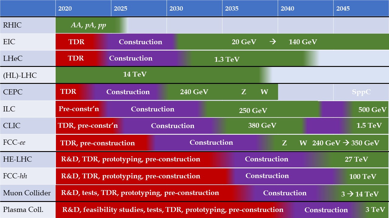
The most critical requirement for the EF colliders is the center-of-mass energy reach. There are four proposals which generally satisfy it (in order of energy reach): 3 TeV CLIC, HE-LHC, 6 to 14 TeV Muon Collider, and FCC-hh/SppC. The next level criteria for EF machines are (in order): cost, facility’s AC wall plug power, machine efficiency and attainable annual integrated luminosity, total annual running cost (including manpower), and the level of R&D effort needed to bring the concept to the level of construction readiness (level of comprehensive TDR). The construction cost is lowest for the HE-LHC and Muon Collider, followed by the 3 TeV CLIC (2) and FCC-hh (another 1.5). The estimated AC site power requirement is lowest for the HE-LHC and the Muon Collider, followed by CLIC (2), then by FCC-hh (another 1.5). As for required duration and scale of R&D efforts to reach the TDR level of readiness, the 3 TeV CLIC project is ahead of other proposals as it requires 10 years of R&D vs about twice that for the HE-LHC, FCC-hh/SppC, and Muon Collider (the latter being at present the only concept without a comprehensive CDR).
Another important factor for any large scale facility is operating cost. Design efforts need to be made, starting from the early concept stage, to enable a sustainable operational efficiency. The history of large-scale collider infrastructures such as at Fermilab and CERN reveals a trend of steadily decreasing normalised operating costs and number of personnel. For example, at the peak of LEP operation CERN had 3,300 staff members, while in the era of LHC, which together with its injectors is a much more complex machine, the laboratory staff has shrunk to 2,300 employees. Such manifestation of progress in technology, operation and maintenance concepts will need to continue for the energy frontier machines. Their designs should place an emphasis on conceiving the individual systems and subsystems such that they can be monitored, maintained and repaired by service suppliers as much as reasonably possible, on investing early-on in a modular architecture of basic components and equipment to enable streamlined operation, service and repair, and on in-kind, collaborative operation.
Arguably the biggest technical challenge for EF hadron and muon colliders is the development of bending magnets with a maximum field up to 16 T. There are fundamental challenges in getting the required current density in SC cables and in dealing with the ultimate magnetic pressures and mechanical stresses in the superconductor and associated components. Some experts estimate that at least 15–20 years might be needed for new approaches to mature and for developing the technology required to overcome the aforementioned limits through continuous R&D efforts. Lowering the maximum field requirement to 12–14 T or even to 6–9 T could greatly reduce the time needed for short-model R&D, prototyping and pre-series work with industry. To realize even higher fields — beyond 16 T, if needed — HTS technology will inevitably be required. At present, the most critical constraint for HTS is its much higher cost, even compared with the Nb3Sn superconductor.
Impressive advances of exploratory plasma wakefield acceleration R&D over the past decade make it important to find out whether a feasible “far future” lepton collider option for particle physics can be based on that technology. One should note that laser- or beam-driven plasma wakefield accelerators (PWFAs) have a significant potential for non-HEP applications and have drawn significant interest and support from the broader community, most notably, because of their possible use in medicine and for generation of X-rays Uesaka and Koyama (2016); Albert and Thomas (2016). Several research and test facilities are already built and operated, and many more are being planned Nghiem et al. (2019). It will be important for HEP accelerator designers to learn from experience, understand the applicability of PWFA advances for particle colliders, and encourage further technological development of the method. The push for more effective and cost-efficient methods of particle acceleration continues in several directions, ranging from the use of exotic particles, like muons, over more advanced magnets and RF cavities, to compact high-gradient acceleration in dielectric structures or solid media plasmas.
Figure 42 illustrates approximate technically limited timelines of future large colliding beam facilities for the next three decades based on the presentations by their proponents given and briefly discussed at the European Particle Physics Strategy Update Symposium (May 13–16, 2019, Granada, Spain) Ellis et al. (2019) and Ref. Colby and Len (2016). In Fig. 42, each of the proposed colliders is considered individually, without any possible interference or interconnection between them, such as a sequential scenario of FCC-hh construction following the completion of FCC-ee operation, as foreseen in the FCC integrated project plan Benedikt et al. (2019a). Several factors are expected to play a role in the actual development: (i) a decisive move — e.g., the approval of any of the four Higgs factory projects will have an impact on the others; (ii) a better understanding of performance, timeline and cost feasibility for the energy-frontier collider proposals after further R&D and more detailed project cost evaluation; and (iii) new discoveries at the LHC or other related particle physics experiments, which might provide clear guidance and preferences for the next generation of accelerator-based HEP programs.
Under circumstances where projects under consideration in the field are becoming so large and costly that no single country or a group of countries can carry them out in isolation, coordination of efforts on regional and global levels becomes ever more critical. Discussion forums on the future of high-energy accelerators such as the Snowmass workshops Brock et al. (2014) and the Particle Physics Project Prioritization Panel (P5) in the US Building for discovery: strategic plan for US particle physics in the global context, Eds. S.Ritz, et al. (2014), the European Particle Physics Strategy updates Ellis et al. (2019), the European and Asian Committees for Future Accelerators (ECFA and ACFA) European Committee for Future Accelerators () (ECFA); Asian Committee for Future Accelerators () (ACFA), the Nuclear Physics European Collaboration Committee (NuPECC Nuclear Physics European Collaboration Committee () (NuPECC)) and a number of European-Union co-funded accelerator development and coordination projects (e.g. TIARA Test Infrastructure and Accelerator Research Area () (TIARA), ARIES Accelerator Research and Development for European Science and Society () (ARIES), E-JADE Europe-Japan Accelerator Development Exchange Programme () (E-JADE) and EuPRAXIA European Plasma Research Accelerator with eXcellence In Applications () (EuPRAXIA)) transcend national or regional boundaries. Even more globally, the International Committee for Future Accelerators (ICFA) Bhat and Rubinstein (2019), created, in 1976, by the International Union of Pure and Applied Physics (IUPAP) International Union of Pure and Applied Physics () (IUPAP), plays an important role as a facilitator of international collaborations, such as, for example, on the LHC, the ILC and CLIC in the recent past, and promotes international efforts in all phases of construction and exploitation of future global accelerator facilities for particle physics.
In this review, we have presented only the most promising options for particle colliders; there are many more ideas and avenues that remain to be explored. Collider beam physics, an astonishingly fertile and dynamic research field, is still breaking new ground. We are certain that some two decades from now, accelerator and beam physicists will have achieved remarkable accomplishments resulting in better, more effective and more economical colliding-beam facilities, as they have done again and again over the past sixty years.
Acknowledgements
We would like to acknowledge fruitful discussions on particle colliders with many colleagues whom we have collaborated over the years. Special thanks go to our colleagues who provided valuable input and shared their views on various topics of this review, including G. Arduini, R. Assmann, M. Benedikt, P. Bhat, C. Biscari, A. Blondel, A. Bogacz, J. Brau, O. Brüning, A. Canepa, W. Chou, A. Grasselino, J.P. Delahaye, D. Denisov, V. Dolgashev, J. Gao, A. Grasselino, E. Gschwendtner, M. Klein, W. Krasny, W. Leemans, E. Levichev, B. List, V. Litvinenko, E. Métral, H. Montgomery, P. Muggli, D. Neuffer, K. Ohmi, K. Oide, H. Padamsee, M. Palmer, R. Palmer, N. Pastrone, Q. Qin, T. Raubenheimer, L. Rivkin, A. Romanenko, M. Ross, L. Rossi, G. Rumolo, D. Schulte, M. Seidel, T. Sen, A. Seryi, D. Shatilov, S. Stapnes, M. Syphers, Y. Tikhonov, F. Willeke, V. Yakovlev, A. Yamamoto, K. Yokoya, A. Zlobin, and M. Zobov. We are grateful to P. Derwent and V. Higgins for carefully reading through the manuscript and helpful feedback.
Some of this material has appeared in other forms written by the authors. Many of the ideas and proposals outlined above were presented and discussed at the European Particle Physics Strategy Update Symposium (May 13–16, 2019, Granada, Spain) Ellis et al. (2019).
V.S. was supported by Fermi National Accelerator Laboratory, which is operated by the Fermi Research Alliance, LLC under Contract No. DE-AC02-07CH11359 with the United States Department of Energy. F.Z. was supported by the European Organization for Nuclear Research, and by the European Commission under the HORIZON 2020 project ARIES, grant agreement no. 730871.
References
- Sessler and Wilson (2014) A. Sessler and E. Wilson, Engines of discovery: a century of particle accelerators (World Scientific, 2014).
- Scharf (1989) W. H. Scharf, Particle accelerators: applications in technology and research (Research Studies Press, 1989).
- Livingston (1954) M. S. Livingston, High energy accelerators (Interscience, 1954).
- nob (2020) “Physics Nobel Prize web site,” http://www.nobelprize.org/prizes/physics/ (2020), Accessed: February 27, 2020.
- Lawrence and Livingston (1932) E. O. Lawrence and M. S. Livingston, Physical Review 40, 19 (1932).
- Haussecker and Chao (2011) E. F. Haussecker and A. W. Chao, Physics in Perspective 13, 146 (2011), we extended the original analysis of the paper from 1939-2009 to 1939-2018.
- Cockcroft and Walton (1932) J. D. Cockcroft and E. T. Walton, Proceedings of the Royal Society of London. Series A, Containing Papers of a Mathematical and Physical Character 136, 619 (1932).
- Van Der Meer (1985) S. Van Der Meer, Reviews of Modern Physics 57, 689 (1985).
- Bruning and Collier (2007) O. Bruning and P. Collier, Nature 448, 285 (2007).
- Englert (2014) F. Englert, Reviews of Modern Physics 86, 843 (2014).
- Higgs (2014) P. W. Higgs, Reviews of Modern Physics 86, 851 (2014).
- (12) Particle Accelerators Around the World, http://www-elsa.physik.uni-bonn.de/accelerator_list.html, accessed: February 19, 2019.
- (13) US DOE Office of Science User Facilities, https://science.energy.gov/user-facilities/, accessed: February 18, 2019.
- (14) 2019 Annual Contributions to CERN budget, https://fap-dep.web.cern.ch/rpc/2019-annual-contributions-cern-budget, accessed: April 1, 2019.
- Perkins (2000) D. H. Perkins, Introduction to high energy physics (Cambridge University Press, 2000) p. 148.
- Hoddeson et al. (1997) L. Hoddeson, L. Brown, M. Dresden, and M. Riordan, The rise of the standard model: A history of particle physics from 1964 to 1979 (Cambridge University Press, 1997).
- Ellis et al. (2003) R. K. Ellis, W. J. Stirling, and B. R. Webber, QCD and collider physics (Cambridge university press, 2003).
- Barger (2018) V. D. Barger, Collider physics (CRC Press, 2018).
- Wideroe (1953) R. Wideroe, Patentschrift, Nr. 876279, klass 21g, Gruppe 36, Ausgegeben am 11 Mai 1953, Tech. Rep. (Deutsches Patentamt, 1953).
- Waloschek (2013) P. Waloschek, The infancy of particle accelerators: Life and work of Rolf Wideroe (Springer Science & Business Media, 2013).
- Kerst et al. (1956) D. Kerst, F. Cole, H. Crane, L. Jones, L. J. Laslett, T. Ohkawa, A. Sessler, K. Symon, K. Terwilliger, and N. V. Nilsen, Physical review 102, 590 (1956).
- O’Neill (1956) G. K. O’Neill, Physical Review 102, 1418 (1956).
- Barber et al. (1959) W. Barber, B. Richter, W. K. Panofsky, G. O’Neill, and B. Gittelman, An experiment on the limits of quantum electrodynamics, Tech. Rep. Report HEPL-170 (Stanford Univ., Calif. Microwave Lab.; Princeton Univ., NJ, 1959).
- (24) G.I. Budker, B.G. Erozolimsky, A.A. Naumov, Proceedings of the meeting on physics and technology of the method of colliding beams, Kharkiv, May 21–25, 1962 - Kharkiv II, 5, in Russian.
- Bernardini et al. (1960) C. Bernardini, G. Corazza, G. Ghigo, and B. Touschek, Il Nuovo Cimento (1955-1965) 18, 1293 (1960).
- Budker (1967) G. Budker, Physics-Uspekhi 9, 534 (1967).
- Levichev et al. (2018) E. B. Levichev, A. N. Skrinsky, G. M. Tumaikin, and Y. M. Shatunov, Physics-Uspekhi 61, 405 (2018).
- Bernardini et al. (1964) C. Bernardini, G. Corazza, G. Di Giugno, J. Haissinski, P. Marin, R. Querzoli, and B. Touschek, Il Nuovo Cimento (1955-1965) 34, 1473 (1964).
- Bernardini (2004) C. Bernardini, Physics in Perspective 6, 156 (2004).
- Gittelman (1965a) B. Gittelman, IEEE Transactions on Nuclear Science 12, 1033 (1965a).
- Rees (1986) J. R. Rees, SLAC Beam Line 9, 1 (March 1986).
- Tigner (1965) M. Tigner, Il Nuovo Cimento (1955-1965) 37, 1228 (1965).
- Amaldi (1976) U. Amaldi, Phys. Lett. 61B, 313 (1976).
- Balakin and Skrinsky (1979) V. E. Balakin and A. N. Skrinsky, In *Les Diablerets 1979, Proceedings, Possibilities and Limitations Of Accelerators and Detectors*, 31-43, Conf. Proc. C791004, 31 (1979).
- Shiltsev (2012a) V. D. Shiltsev, Physics-Uspekhi 55, 965 (2012a).
- Myers and Schopper (2013) S. Myers and H. Schopper, Landolt Bornstein 21 (2013).
- De Florian et al. (2016) D. De Florian et al., arXiv preprint arXiv:1610.07922 (2016).
- Frauenfelder and Henley (1991) H. Frauenfelder and E. Henley, Subatomic physics (2nd edition) (Prentice-Hall, 1991) p. 286.
- Eichten et al. (1984) E. Eichten, I. Hinchliffe, K. Lane, and C. Quigg, Reviews of Modern Physics 56, 579 (1984).
- Quigg (2011a) C. Quigg, arXiv preprint arXiv:1101.3201 (2011a).
- Salam and Weiler (2017) G. Salam and A. Weiler, (2017).
- Teng (2001) L. Teng, in Proceedings of the Second Asian Particle Accelerator Conference, Beijing, China (2001) pp. 926–933.
- Tanabashi et al. (2018) M. Tanabashi et al., Physical Review D 98, 030001 (2018).
- Green (2000) D. Green, The physics of particle detectors, Vol. 12 (Cambridge University Press, 2000).
- Grupen and Shwartz (2008) C. Grupen and B. Shwartz, Particle detectors, Vol. 26 (Cambridge University Press, 2008).
- Ellis et al. (2019) R. Ellis, H. Abramowitz, et al., arXiv preprint arXiv:1910.11775 (2019).
- Month (2003) M. Month, Weep for Isabelle: a rhapsody in a minor key: a historical novel depicting the rise and fall of big physics in the second half of the twentieth century (AvantGarde Press, 2003).
- Crease (2005a) R. P. Crease, Physics in Perspective 7, 330 (2005a).
- Crease (2005b) R. P. Crease, Physics in Perspective 7, 404 (2005b).
- Yarba (1990) V. Yarba, Particle Accelerators 26, 131 (1990).
- Kuiper (1994) B. Kuiper, Europhysics News 25, 66 (1994).
- Wojcicki (2009) S. Wojcicki, in Reviews Of Accelerator Science And Technology: Volume 2: Medical Applications of Accelerators (World Scientific, 2009) pp. 265–301.
- Riordan et al. (2015) M. Riordan, L. Hoddeson, and A. W. Kolb, Tunnel visions: the rise and fall of the Superconducting Super Collider (University of Chicago Press, 2015).
- Shiltsev (2014) V. Shiltsev, Journal of Instrumentation 9, T07002 (2014).
- Fernow and Fernow (1989) R. C. Fernow and R. C. Fernow, Introduction to experimental particle physics (Cambridge university press, 1989).
- Hauptman (2011) J. Hauptman, Particle physics experiments at high energy colliders (John Wiley and Sons, 2011).
- Shiltsev (2011) V. Shiltsev, Modern Physics Letters A 26, 761 (2011).
- Ellis (2018) J. Ellis, arXiv preprint arXiv:1810.11263 (2018).
- Giudice (2019) G. F. Giudice, preprint arXiv:1902.07964 (2019).
- Chao et al. (2013a) A. W. Chao, K. H. Mess, et al., Handbook of accelerator physics and engineering (World scientific, 2013).
- Myers and Brüning (2016) S. Myers and O. Brüning, Challenges and Goals for Accelerators in the XXI Century (World Scientific, 2016).
- Senes et al. (2018) E. Senes, T. Argyropoulos, F. Tecker, and W. Wuensch, Physical Review Accelerators and Beams 21, 102001 (2018).
- Broemmelsiek et al. (2018) D. Broemmelsiek et al., New Journal of Physics 20, 113018 (2018).
- Tollestrup and Todesco (2008) A. Tollestrup and E. Todesco, in Reviews Of Accelerator Science And Technology: Volume 1 (World Scientific, 2008) pp. 185–210.
- Clarke (2004) J. A. Clarke, The science and technology of undulators and wigglers, Vol. 4 (Oxford University Press on Demand, 2004).
- Yamamoto (2003) A. Yamamoto, Nuclear Instrument and Methods, Phys. Res., A 494, 255 (2003).
- Barber et al. (1984) D. Barber, G. Ripken, J. Kewisch, R. Schmidt, and R. Rossmanith, Particle Accelerators 17, 243 (1984).
- Parkhomchuk and Skrinsky (2000) V. Parkhomchuk and A. Skrinsky, Physics-Uspekhi 43, 433 (2000).
- Carlsten (1995) B. E. Carlsten, Part. Accel. 49, 27 (1995).
- Evans (2016) L. Evans, Technological Forecasting and Social Change 112, 4 (2016).
- Tanabe (2005) J. T. Tanabe, Iron dominated electromagnets: design, fabrication, assembly and measurements (World Scientific Publishing Company, 2005).
- Mess et al. (1996) K.-H. Mess, S. Wolff, et al., Superconducting accelerator magnets (World Scientific, 1996).
- Schoerling and Zlobin (2019) D. Schoerling and A. Zlobin, eds., Nb3Sn Accelerator Magnets (Springer, 2019) iSBN 978-3-030-16118-7.
- Rossi and Bottura (2012) L. Rossi and L. Bottura, Reviews of accelerator science and technology 5, 51 (2012).
- Phinney et al. (2007) N. Phinney, N. Toge, and N. Walker, arXiv preprint arXiv:0712.2361 (2007).
- Bailey (2012) R. Bailey, arXiv preprint arXiv:1201.4648 (2012).
- Delahaye (2018) J. P. Delahaye, ARIES Muon Collider Workshop, Padua, 2–3 July 2018 (2018).
- Martinello et al. (2018) M. Martinello, M. Checchin, A. Romanenko, A. Grassellino, S. Aderhold, S. Chandrasekeran, O. Melnychuk, S. Posen, and D. Sergatskov, Physical Review Letters 121, 224801 (2018).
- Padamsee et al. (2008) H. Padamsee, J. Knobloch, and T. Hays, RF superconductivity for accelerators, Vol. 2011 (Wiley-VCH, 2008).
- Erickson et al. (1984) R. Erickson et al., SLAC Linear Collider Design Handbook, Tech. Rep. (SLAC, 1984).
- Phinney (2000) N. Phinney, arXiv preprint physics/0010008 (2000).
- Lavine (1992) T. L. Lavine, in 3rd European Particle Accelerator Conference (EPAC’92), Berlin, 24-28 March, 1992, Vol. 1 (JACoW Publishing, Geneva, Switzerland, 1992) pp. 302–304.
- Sands (1970) M. Sands, The physics of electron storage rings: an introduction, Tech. Rep. SLAC-121 (Stanford Linear Accelerator Center, Menlo Park, CA (USA), 1970).
- Brandt et al. (2000) D. Brandt, H. Burkhardt, M. Lamont, S. Myers, and J. Wenninger, Reports on Progress in Physics 63, 939 (2000).
- Assmann et al. (2002a) R. W. Assmann, M. Lamont, and S. Myers, Nucl. Phys. B, Proc. Suppl. 109, 17 (2002a).
- Brown et al. (2001) P. Brown, O. Brunner, A. Butterworth, E. Ciapala, H. Frischholz, G. Geschonke, E. Peschardt, and J. Sladen, in PACS2001. Proceedings of the 2001 Particle Accelerator Conference (Cat. No. 01CH37268), Vol. 2 (IEEE, 2001) pp. 1059–1061.
- Weingarten (1996) W. Weingarten, Superconducting cavities: basics, Tech. Rep. CERN-1996-003 (CERN, 1996).
- Butterworth et al. (2008) A. Butterworth, P. Brown, O. Brunner, E. Ciapala, H. Frischholz, G. Geschonke, E. Peschardt, and J. Sladen, Nucl. Instrum. Methods Phys. Res., A 587, 151 (2008).
- Minty and Zimmermann (2013) M. G. Minty and F. Zimmermann, Measurement and control of charged particle beams (Springer Science & Business Media, 2013).
- Palmer (1988) R. Palmer, Energy scaling, crab crossing and the pair problem, Tech. Rep. SLAC-PUB-4707 (Stanford Linear Accelerator Center, Menlo Park, CA (USA), 1988).
- Oide and Yokoya (1989) K. Oide and K. Yokoya, Physical Review A 40, 315 (1989).
- Sun et al. (2009) Y.-P. Sun et al., Physical Review Special Topics-Accelerators and Beams 12, 101002 (2009).
- Akre et al. (2002) R. Akre, L. Bentson, P. Emma, and P. Krejcik, Bunch length measurements using a transverse RF deflecting structure in the SLAC linac, Tech. Rep. SLAC-PUB-9241 (Stanford Linear Accelerator Center, Menlo Park, CA (USA), 2002).
- Marcellini and Alesini (2004) F. Marcellini and D. Alesini, in 9th European Particle Accelerator Conference (EPAC’04), Lucerne, Switzerland, 5-9 July, 2004, Vol. 4 (JACoW Publishing, Geneva, Switzerland, 2004) pp. 689–691.
- Barron (1985) R. F. Barron, Cryogenic systems (Oxford University press, 1985).
- Lafferty (1998) J. M. Lafferty, ed., Foundations of vacuum science and technology (John Wiley and Sons, 1998).
- Edwards and Syphers (2008) D. A. Edwards and M. J. Syphers, An introduction to the physics of high energy accelerators (John Wiley & Sons, 2008).
- Peggs and Satogata (2017) S. Peggs and T. Satogata, Introduction to accelerator dynamics (Cambridge University Press, 2017).
- Lee (2018) S.-Y. Lee, Accelerator physics (World Scientific Publishing, 2018).
- Chao et al. (2013b) A. W. Chao, K. H. Mess, M. Tigner, and F. Zimmermann, Handbook of accelerator physics and engineering; 2nd ed. (World Scientific, Singapore, 2013).
- Magnus and Winkler (2013) W. Magnus and S. Winkler, Hill’s equation (Courier Corporation, 2013).
- Gareyte (1999) J. Gareyte, CERN Report CERN-SL-00-039 AP (1999).
- Persson et al. (2017a) T. Persson et al., Physical Review Accelerators and Beams 20, 061002 (2017a).
- Wiedemann (2012) H. Wiedemann, Particle Accelerator Physics II: Nonlinear and Higher-Order Beam Dynamics (Springer Science & Business Media, 2012).
- Courant and Snyder (1958) E. D. Courant and H. S. Snyder, Annals of physics 3, 1 (1958).
- Brown (2004) I. G. Brown, The physics and technology of ion sources (John Wiley & Sons, 2004).
- Wolf (2017) B. Wolf, Handbook of ion sources (CRC press, 2017).
- Veksler (1944) V. Veksler, Doklady Akademii Nauk SSSR 43, 346 (1944), in Russian.
- McMillan (1945) E. M. McMillan, Physical Review 68, 143 (1945).
- Baudrenghien et al. (2011) P. Baudrenghien, A. C. Butterworth, M. Jaussi, T. Mastoridis, G. Papotti, E. N. Shaposhnikova, and J. Tuckmantel, 2nd International Particle accelerator Conference, IPAC 2011, San Sebastian, Spain, September 4-9, 2011, Conf. Proc. C110904, 1819 (2011).
- Hirata (1995) K. Hirata, Physical Review Letters 74, 2228 (1995).
- Napoly (1993) O. Napoly, Particle Accelerators 40, 181 (1993).
- Bogomyagkov et al. (2018) A. Bogomyagkov, V. Druzhinin, E. Levichev, A. Milstein, and S. Sinyatkin, in EPJ Web of Conferences, Vol. 181 (EDP Sciences, 2018) p. 01032.
- Furman (1994) M. A. Furman, 4th European Particle Accelerator Conference (EPAC 94) London, England, June 27-July 1, 1994, Conf. Proc. C940627, 1144 (1994).
- Otboyev and Perevedentsev (1999) A. V. Otboyev and E. A. Perevedentsev, Phys. Rev. ST Accel. Beams 2, 104401 (1999).
- Yokoya and Chen (1992) K. Yokoya and P. Chen, Frontiers of Particle Beams: Intensity Limitations: Proceedings of a Topical Course held by the Joint US-CERN School on Particle Accelerators, Hilton Head Island, South Carolina, 7-14 November 1990, Lect. Notes Phys. 400, 415 (1992).
- Robinson and Voss (1966) K. W. Robinson and G. A. Voss, “Possible use of the CEA directly as a colliding beam facility,” (1966).
- Levichev (2014) E. Levichev, Reviews of Accelerator Science and Technology 7, 207 (2014).
- Telnov (1987) V. I. Telnov, Nuclear Instruments and Methods in Physics Research Section A: Accelerators, Spectrometers, Detectors and Associated Equipment 260, 304 (1987).
- Bernardini et al. (1963) C. Bernardini, G. Corazza, G. Di Giugno, G. Ghigo, J. Haissinski, P. Marin, R. Querzoli, and B. Touschek, Physical Review Letters 10, 407 (1963).
- Piwinski (1988) A. Piwinski, in Frontiers of Particle Beams (Springer, 1988) pp. 297–309.
- Bjorken (1983) J. Bjorken, Particle Accelerators 13, 115 (1983).
- Piwinski et al. (2018) A. Piwinski, J. D. Bjorken, and S. K. Mtingwa, Physical Review Accelerators and Beams 21, 114801 (2018).
- Levedev et al. (1994) V. Levedev, V. Parkhomchuk, V. Shiltsev, and G. Stupakov, Particle Accelerators 44, 147 (1994).
- Zimmermann (1994) F. Zimmermann, Particle Accelerators 49, 67 (1994).
- Skrinsky and Parkhomchuk (1981) A. Skrinsky and V. Parkhomchuk, Sov. J. Part. Nucl 12, 210 (1981).
- Parkhomchuk and Skrinsky (2008) V. Parkhomchuk and A. Skrinsky, Reviews of Accelerator Science and Technology 1, 237 (2008).
- Wiedemann (2003) H. Wiedemann, Particle Accelerator Physics (Springer, 2003).
- Nagaitsev et al. (2006) S. Nagaitsev et al., Physical Review Letters 96, 044801 (2006).
- Lebedev and Shiltsev (2014) V. Lebedev and V. Shiltsev, Accelerator physics at the Tevatron collider (Springer, 2014).
- Schröder et al. (1990) S. Schröder et al., Physical Review Letters 64, 2901 (1990).
- Hangst et al. (1991) J. Hangst, M. Kristensen, J. Nielsen, O. Poulsen, J. Schiffer, and P. Shi, Physical Review Letters 67, 1238 (1991).
- Lauer et al. (1998) I. Lauer, U. Eisenbarth, M. Grieser, R. Grimm, P. Lenisa, V. Luger, T. Schätz, U. Schramm, D. Schwalm, and M. Weidemüller, Phys. Rev. Lett. 81, 2052 (1998).
- G.I.Budker (1970a) G.I.Budker, Proceedings of the 7th Int. Conf. Part. Accel. Physics (Yerevan, 1969) 1, 33 (1970a).
- Neuffer (1983) D. Neuffer, Particle Accelerators 14, 75 (1983).
- Adams et al. (2019) D. Adams et al., The European Physical Journal C 79, 257 (2019).
- Chao (1985) A. W. Chao, in AIP Conference Proceedings, Vol. 127 (AIP, 1985) pp. 201–242.
- Pieloni and Herr (2013) T. Pieloni and W. Herr, Proceedings, 2013 CERN Accelerator School (2013).
- Shiltsev (1996) V. Shiltsev, Nuclear Instruments and Methods in Physics Research Section A: Accelerators, Spectrometers, Detectors and Associated Equipment 374, 137 (1996).
- Dikanskij and Pestrikov (1982) N. Dikanskij and D. Pestrikov, Particle Accelerators 12, 27 (1982).
- Chao and Ruth (1984) A. Chao and R. D. Ruth, Particle Accelerators 16, 201 (1984).
- Yokoya et al. (1989) K. Yokoya, Y. Funakoshi, E. Kikutani, H. Koiso, and J. Urakawa, Part. Accel. 27, 181 (1989).
- Alexahin (1998) Y. I. Alexahin, Part. Accel. 59, 43 (1998).
- Krishnagopal and Siemann (1991) S. Krishnagopal and R. Siemann, Physical Review Letters 67, 2461 (1991).
- Shiltsev et al. (2005) V. Shiltsev, Y. Alexahin, V. Lebedev, P. Lebrun, R. Moore, T. Sen, A. Tollestrup, A. Valishev, and X. Zhang, Physical Review Special Topics-Accelerators and Beams 8, 101001 (2005).
- Seeman (1986) J. T. Seeman, in Lecture Notes in Physics (Springer, 1986) pp. 121–153.
- Shiltsev (2016) V. D. Shiltsev, Electron lenses for super-colliders (Springer, 2016).
- Danilov et al. (1996) V. Danilov, P. Ivanov, I. Koop, I. Nesterenko, E. Perevedentsev, D. Shatilov, Y. M. Shatunov, and A. Skrinsky, in Proc. EPAC, Vol. 96 (1996) p. 1149.
- Young et al. (1998) E. Young, S. Henderson, R. M. Littauer, B. McDaniel, T. Pelaia, and R. Talman, (1998).
- Berkaev et al. (2012) D. Berkaev et al., Nuclear Physics B-Proceedings Supplements 225, 303 (2012).
- Shatunov et al. (2016) P. Shatunov et al., Physics of Particles and Nuclei Letters 13, 995 (2016).
- Raimondi (2006) P. Raimondi, “Proceedings of the 2nd SuperB Workshop, Frascati, Italy,” (2006).
- Raimondi et al. (2007) P. Raimondi, D. N. Shatilov, and M. Zobov, arXiv preprint physics/0702033 (2007).
- Zobov et al. (2010) M. Zobov et al., Physical Review Letters 104, 174801 (2010).
- Hirata and Ruggiero (1990) K. Hirata and F. Ruggiero, Proceedings, 14th International Conference on High-Energy Accelerators, HEACC 1989, pt.1-5: Tsukuba, Japan, August 22-26, 1989, Part. Accel. 28, 137 (1990).
- Weng (1987) W. Weng, in AIP Conference Proceedings, Vol. 153 (AIP, 1987) pp. 348–389.
- Reiser (2008) M. Reiser, Theory and design of charged particle beams (John Wiley & Sons, 2008).
- Hofmann (2017) I. Hofmann, Space Charge Physics for Particle Accelerators (Springer, 2017).
- Chao (1993) A. W. Chao, Physics of collective beam instabilities in high energy accelerators (Wiley, 1993).
- Ng (2006) K.-Y. Ng, Physics of intensity dependent beam instabilities (World Scientific, 2006).
- Heifets and Kheifets (1991) S. Heifets and S. Kheifets, Reviews of Modern Physics 63, 631 (1991).
- Kheifets and Zotter (1998) S. Kheifets and B. Zotter, Impedances and Wakes in High Energy Particle Accelerators (World Scientific, 1998).
- Ohmi (1995) K. Ohmi, Physical Review Letters 75, 1526 (1995).
- Raubenheimer and Zimmermann (1995) T. Raubenheimer and F. Zimmermann, Physical Review E 52, 5487 (1995).
- Zimmermann (2004) F. Zimmermann, Physical Review Special Topics-Accelerators and Beams 7, 124801 (2004).
- Flanagan et al. (2005) J. Flanagan, K. Ohmi, H. Fukuma, S. Hiramatsu, M. Tobiyama, and E. Perevedentsev, Physical Review Letters 94, 054801 (2005).
- Courant and Sessler (1966) E. D. Courant and A. M. Sessler, Review of Scientific Instruments 37, 1579 (1966).
- Metral (1999) E. Metral, Particle Accelerators 62, 259 (1999).
- Karliner and Popov (2005) M. Karliner and K. Popov, Nuclear Instruments and Methods in Physics Research Section A: Accelerators, Spectrometers, Detectors and Associated Equipment 537, 481 (2005).
- Burov (2016) A. Burov, Physical Review Accelerators and Beams 19, 084402 (2016).
- Kulikov et al. (2001) A. Kulikov, A. Fisher, S. Heifets, J. Seeman, M. Sullivan, U. Wienands, and W. Kozanecki, in Proceedings of the 2001 Particle Accelerator Conference (Cat. No. 01CH37268), Vol. 3 (IEEE, 2001) pp. 1903–1905.
- Fischer et al. (2008) W. Fischer et al., Physical Review Special Topics-Accelerators and Beams 11, 041002 (2008).
- Yin Vallgren et al. (2011) C. Yin Vallgren, G. Arduini, J. Bauche, S. Calatroni, P. Chiggiato, K. Cornelis, P. C. Pinto, B. Henrist, E. Métral, H. Neupert, G. Rumolo, E. Shaposhnikova, and M. Taborelli, Phys. Rev. ST Accel. Beams 14, 071001 (2011).
- Dominguez et al. (2013) O. Dominguez, K. Li, G. Arduini, E. Metral, G. Rumolo, F. Zimmermann, and H. M. Cuna, Physical Review Special Topics-Accelerators and Beams 16, 011003 (2013).
- Mess and Seidel (1994) K.-H. Mess and M. Seidel, Nuclear Instruments and Methods in Physics Research Section A: Accelerators, Spectrometers, Detectors and Associated Equipment 351, 279 (1994).
- Von Holtey (1987) G. Von Holtey, Electron beam collimation at LEP energies, Tech. Rep. CERN-LEP-BI-87-04 (CERN, 1987).
- Mokhov et al. (2011) N. Mokhov et al., Journal of Instrumentation 6, T08005 (2011).
- Schmidt et al. (2006) R. Schmidt et al., New Journal of Physics 8, 290 (2006).
- Valentino et al. (2012) G. Valentino, R. Assmann, R. Bruce, S. Redaelli, A. Rossi, N. Sammut, and D. Wollmann, Physical Review Special Topics-Accelerators and Beams 15, 051002 (2012).
- Mokhov et al. (2010) N. Mokhov et al., International Journal of Modern Physics A 25, 98 (2010).
- Scandale et al. (2016) W. Scandale et al., Physics Letters B 758, 129 (2016).
- Stancari et al. (2011) G. Stancari, A. Valishev, G. Annala, G. Kuznetsov, V. Shiltsev, D. Still, and L. Vorobiev, Physical Review Letters 107, 084802 (2011).
- Fischer (1987) G. E. Fischer, in AIP Conference Proceedings, Vol. 153 (AIP, 1987) pp. 1047–1119.
- Rossbach (1987) J. Rossbach, Particle Accelerators 23, 121 (1987).
- Parkhomchuk et al. (1993) V. Parkhomchuk, V. Shiltsev, and G. Stupakov, Particle Accelerators 46, 241 (1993).
- Sery and Napoly (1996) A. Sery and O. Napoly, Physical review E 53, 5323 (1996).
- Shiltsev (2010a) V. Shiltsev, Physical Review Special Topics-Accelerators and Beams 13, 094801 (2010a).
- Mokhov et al. (2012) N. Mokhov, Y. Alexahin, V. Kashikhin, S. Striganov, and A. Zlobin, arXiv preprint arXiv:1202.3979 (2012).
- Boscolo et al. (2017) M. Boscolo, H. Burkhardt, and M. Sullivan, Physical Review Accelerators and Beams 20, 011008 (2017).
- Derbenev et al. (1978) Y. S. Derbenev, A. Skrinsky, Y. M. Shatunov, G. Tumaikin, S. Serednyakov, and A. Kondratenko, Particle Accelerators 8, 115 (1978).
- Derbenev et al. (1980) Y. S. Derbenev, A. Skrinsky, Y. M. Shatunov, G. Tumaikin, S. Serednyakov, and A. Kondratenko, Particle Accelerators 10, 177 (1980).
- Huang et al. (1994) H. Huang et al., Physical Review Letters 73, 2982 (1994).
- Barber et al. (1995) D. Barber et al., Physics Letters B 343, 436 (1995).
- Bai et al. (2006) M. Bai et al., Physical Review Letters 96, 174801 (2006).
- Blinov et al. (2009) V. Blinov, A. Bogomyagkov, N. Y. Muchnoi, S. Nikitin, I. Nikolaev, A. Shamov, and V. Zhilich, Nuclear Instruments and Methods in Physics Research Section A: Accelerators, Spectrometers, Detectors and Associated Equipment 598, 23 (2009).
- Voss (1996) G.-A. Voss, in History of Original Ideas and Basic Discoveries in Particle Physics (Springer, 1996) pp. 465–487.
- Pellegrini and Sessler (1995) C. M. Pellegrini and A. M. Sessler, eds., The Development of Colliders (American Institute of Physics, 1995).
- Sessler and Wilson (2006) A. Sessler and E. Wilson, Engines of discovery: A Century of particle accelerators (World Scientific, 2006).
- Scandale (2014) W. Scandale, Reviews of Accelerator Science and Technology 7, 9 (2014).
- Barber et al. (1966) W. Barber, B. Gittelman, G. O’Neill, and B. Richter, Physical Review Letters 16, 1127 (1966).
- Gittelman (1965b) B. Gittelman, IEEE Transactions on Nuclear Science 12, 1033 (1965b).
- Skrinsky (2002) A. Skrinsky, Nuclear Instruments and Methods in Physics Research Section A: Accelerators, Spectrometers, Detectors and Associated Equipment 494, 1 (2002).
- The Orsay Storage Ring Group: Marin, P.C., et al. (1965) The Orsay Storage Ring Group: Marin, P.C., et al., Proc. Vth Intl. Conf. on High Energy Accelerators, Frascati , 271 (1965).
- Adone Group (1971) Adone Group, IEEE Transactions on Nuclear Science 18, 217 (1971).
- Balakin et al. (1971) V. Balakin, G. Budker, E. Pakhtusova, V. Sidorov, A. Skrinsky, G. Tumaikin, and A. Khabakhpashev, Physics Letters B 34, 328 (1971).
- Cosme et al. (1972) G. Cosme, B. Jean-Marie, S. Jullian, F. Laplanche, J. Lefrançois, A. Liberman, G. Parrour, J. Repellin, G. Sauvage, and G. Szklarz, Physics Letters B 40, 685 (1972).
- Bacci et al. (1972) C. Bacci, G. Penso, G. Salvini, B. Stella, R. Baldini-Celio, G. Capon, C. Mencuccini, G. Murtas, A. Reale, and M. Spinetti, Physics Letters B 38, 551 (1972).
- Kurdadze et al. (1972) L. Kurdadze, A. Onuchin, S. Serednyakov, V. Sidorov, and S. Eidelman, Physics Letters B 42, 515 (1972).
- Haissinski (1969) J. Haissinski, in 8th CERN School of Physics, CERN-1969-029 (CERN, 1969) pp. 61–96.
- Sokolov and Ternov (1964) A. Sokolov and I. Ternov, Soviet Physics Doklady, 8, 1203 (1964).
- Baier (1972) V. Baier, Soviet Physics Uspekhi 14, 695 (1972).
- Paterson (1975) J. Paterson, IEEE (Inst. Electr. Electron. Eng.) Trans. Nucl. Sci , 1366 (1975).
- The Orsay Storage Ring Group (1979) The Orsay Storage Ring Group, IEEE Transactions on Nuclear Science 26, 3559 (1979).
- Le Duff et al. (1980) J. Le Duff, M. Level, P. Marin, E. Sommer, and H. Zyngier, in 11th International Conference on High-Energy Accelerators (Springer, 1980) pp. 707–712.
- Derbenev (1973) Y. Derbenev, Collective Instability of Compensated Colliding Beams, Tech. Rep. SLAC-TRANS-0151 (1973).
- Podobedov and Siemann (1995) B. Podobedov and R. H. Siemann, Phys. Rev. E52, 3066 (1995).
- G.M.Tumaikin (1977) G.M.Tumaikin, in 10th Intl. Conf. on High Energy Particle Accelerators, Serpukhov, Vol. 1 (1977) p. 443.
- Skrinskii and Shatunov (1989) A. N. Skrinskii and Y. M. Shatunov, Physics-Uspekhi 32, 548 (1989).
- Nesemann and Wille (1983) H. Nesemann and K. Wille, IEEE Transactions on Nuclear Science 30, 1998 (1983).
- McDaniel (1981) B. McDaniel, IEEE Transactions on Nuclear Science 28, 1983 (1981).
- VEPP-4 Group (1980) VEPP-4 Group, in 11th International Conference on High-Energy Accelerators: Geneva, Switzerland, July 7–11, 1980 (Springer, 1980) pp. 38–42.
- Herb et al. (1977) S. Herb, D. Hom, L. Lederman, J. Sens, H. Snyder, J. Yoh, J. Appel, B. Brown, C. Brown, W. R. Innes, et al., Physical Review Letters 39, 252 (1977).
- Finocchiaro et al. (1980) G. Finocchiaro et al., Physical Review Letters 45, 222 (1980).
- Bohringer et al. (1980) T. Bohringer et al., Physical Review Letters 44, 1111 (1980).
- Artamonov et al. (1984) A. Artamonov et al., Physics Letters B 137, 272 (1984).
- Baru et al. (1992) S. Baru et al., Zeitschrift fur Physik C Particles and Fields 53, 219 (1992).
- Patrignani et al. (2013) C. Patrignani, T. K. Pedlar, and J. L. Rosner, Annual Review of Nuclear and Particle Science 63, 21 (2013).
- Berkelman (2004) K. Berkelman, A Personal History of CESR and CLEO: The Cornell Electron Storage Ring and Its Main Particle Detector Facility (World Scientific, 2004).
- Shiltsev (2004) V. Shiltsev, in Contributed to Symposium Honoring Alvin Tollestrup, Fermilab, 2004, FERMILAB-CONF-04-126-AD (2004).
- Rubin (1989) D. Rubin, Particle Accelerators 26, 63 (1989).
- Belomestnykh (2012) S. Belomestnykh, in Reviews of Accelerator Science and Technology: Volume 5: Applications of Superconducting Technology to Accelerators (World Scientific, 2012) pp. 147–184.
- Talman (1995) R. Talman, Physical Review Letters 74, 1590 (1995).
- Young et al. (1997) E. Young, S. Henderson, R. Littauer, B. McDaniel, T. Pelaia, and R. Talman, Proc. 17th Particle Accelerator Conf. (PAC’97), Vancouver, Canada , 1542 (1997).
- Voss et al. (1979) G.-A. Voss, W. Bothe, E. Dasskowski, D. Degele, C. Dehne, A. Febel, H. Frese, H. Gerke, G. Hemmie, G. Hochweller, et al., IEEE Transactions on Nuclear Science 3, 2969 (1979).
- Helm et al. (1983) R. Helm, M. Allen, A. Chao, M. Donald, S. Kheifets, T. Martin, R. Miller, P. Morton, J. Paterson, J. Rees, et al., IEEE Transactions on Nuclear Science 30, 2001 (1983).
- Nishikawa et al. (1983) T. Nishikawa, S. Ozaki, and Y. Kimura, Surveys in High Energy Physics 3, 161 (1983).
- Kimura (1986) Y. Kimura, TRISTAN project and KEK activities, Tech. Rep. (1986).
- Kohaupt (1980) R. D. Kohaupt, Proceedings, 11th International Conference on High-Energy Accelerators, HEACC 1980: CERN, Geneva, Switzerland, July 7-11, 1980, Experientia 40, 562 (1980).
- Bell et al. (1990) B. Bell, H. Friedsam, W. Oren, and R. Ruland, Datum definition problems in accelerator alignment, Tech. Rep. SLAC-PUB-5226 (Stanford Linear Accelerator Center, Menlo Park, CA (USA), 1990).
- Baudrenghien and Collier (1996) P. Baudrenghien and P. Collier, Double batch injection into LEP, Tech. Rep. CERN-SL-96-021-OP (CERN, 1996).
- Assmann et al. (2002b) R. Assmann, M. Lamont, S. Myers, et al., Nuclear Physics B-Proceedings Supplements 109, 17 (2002b).
- Schael et al. (2006) S. Schael et al. (ALEPH, DELPHI, L3, OPAL, SLD, LEP Electroweak Working Group, SLD Electroweak Group, SLD Heavy Flavour Group), Phys. Rept. 427, 257 (2006), arXiv:hep-ex/0509008 [hep-ex] .
- Janot and Jadach (2020) P. Janot and S. Jadach, Physics Letters B 803, 135319 (2020).
- Assmann et al. (1999) R. Assmann et al., The European Physical Journal C-Particles and Fields 6, 187 (1999).
- Dehning et al. (1990) B. Dehning, A. Melissinos, F. Perrone, C. Rizzo, and G. Von Holtey, Physics Letters B 249, 145 (1990).
- Besnier et al. (1984) G. Besnier, D. Brandt, and B. Zotter, Particle Accelerators 17, 51 (1984).
- Danilov and Perevedentsev (1997) V. Danilov and E. Perevedentsev, Nuclear Instruments and Methods in Physics Research Section A: Accelerators, Spectrometers, Detectors and Associated Equipment 391, 77 (1997).
- Assmann and Cornelis (2000) R. Assmann and K. Cornelis, in Particle accelerator. Proceedings, 7th European Conference, EPAC 2000, Vienna, Austria, June 26-30, 2000. Vol. 1-3 (2000) pp. 1187–1189.
- Alley et al. (1995) R. Alley, H. Aoyagi, J. Clendenin, J. Frisch, C. Garden, E. Hoyt, R. Kirby, L. Klaisner, A. Kulikov, R. Miller, et al., Nuclear Instruments and Methods in Physics Research Section A: Accelerators, Spectrometers, Detectors and Associated Equipment 365, 1 (1995).
- Balakin et al. (1983) V. Balakin, A. Novokhatsky, and V. Smirnov, in Conf. on High Energy Accelerators, Fermilab (1983) p. 119.
- Chao et al. (1980) A. W. Chao, B. Richter, and C.-Y. Yao, Nuclear Instruments and Methods 178, 1 (1980).
- Seeman (1992) J. T. Seeman, in AIP Conference Proceedings, Vol. 255 (AIP, 1992) pp. 19–35.
- Emma et al. (1997) P. Emma, L. J. Hendrickson, P. Raimondi, and F. Zimmermann, 17th IEEE Particle Accelerator Conference (PAC 97): Accelerator Science, Technology and Applications Vancouver, British Columbia, Canada, May 12-16, 1997, Conf. Proc. C970512, 452 (1997).
- Hendrickson et al. (1999) L. Hendrickson, S. Bes, P. Grossberg, D. McCormick, N. Phinney, P. Raimondi, and M. Ross, in International Conference on Accelerator and Large Experimental Physics Control Systems (ICALEPCS 97) Beijing, China, November 3-7, 1997 (1999).
- Clendenin et al. (1988) J. E. Clendenin et al., in 14th International Linear Accelerator Conference (LINAC88) Williamsburg, Virginia, October 3-7, 1988 (1988).
- Krejcik et al. (1992) P. Krejcik et al., 3rd European Particle Accelerator Conference (EPAC 92) Berlin, Germany, March 24-28, 1992, Conf. Proc. C920324, 527 (1992).
- Bambade et al. (1989) P. Bambade, R. Erickson, W. A. Koska, W. Kozanecki, N. Phinney, and S. Wagner, Physical Review Letters 62, 2949 (1989).
- Bonvicini et al. (1989) G. Bonvicini, E. Gero, R. Frey, W. Koska, C. Field, N. Phinney, and A. Minten, Physical Review Letters 62, 2381 (1989).
- Barklow et al. (1999) T. Barklow et al., in Proceedings, 1999 Particle Accelerator Conference (PAC’99): New York, New York, March 29-April 2, 1999 (1999) pp. 307–309.
- Abe et al. (2000) K. Abe et al. (The SLD Collaboration), Phys. Rev. Lett. 84, 5945 (2000).
- PEP-II Collaboration (1993) PEP-II Collaboration, PEP-II Conceptual Design Report, Tech. Rep. SLAC Report SLAC-418 and LBL-PUB-5379 (1993).
- tog (1995) KEK B-Factory Design Report, Tech. Rep. KEK-REPORT-95-07 (1995).
- Bevan et al. (2014) A. Bevan, B. Golob, T. Mannel, S. Prell, B. Yabsley, H. Aihara, F. Anulli, N. Arnaud, T. Aushev, M. Beneke, et al., The European Physical Journal C 74, 3026 (2014).
- Seeman (2015) J. Seeman, in Proceedings, 55th ICFA Advanced Beam Dynamics Workshop on High Luminosity Circular e+e- Colliders – Higgs Factory (HF2014): Beijing, China, October 9-12, 2014 (2015) p. SAT4A1.
- Satoh (2010) M. Satoh, Proceedings, 1st International Particle Accelerator Conference (IPAC’10): Kyoto, Japan, May 23-28, 2010, Conf. Proc. C100523, THPD006 (2010).
- Seeman (2008a) J. Seeman, in 11th European Particle Accelerator Conference (EPAC 2008), Genoa, Italy (2008) pp. 23–28.
- Oide (2009) K. Oide, Progress of Theoretical Physics 122, 69 (2009).
- Oide (2014) K. Oide, Reviews of Accelerator Science and Technology 7, 35 (2014).
- Y.Funakoshi (2014) Y.Funakoshi, Proc.ICFA Mini-Workshop on Beam-Beam Effects in Hadron Colliders, CERN Yellow Report CERN-2014-004, 27 (2014).
- Verdu-Andres et al. (2016) S. Verdu-Andres, S. Belomestnykh, I. Ben-Zvi, R. Calaga, Q. Wu, and B. Xiao, Nuclear and particle physics proceedings 273, 193 (2016).
- Johnsen (1973) K. Johnsen, Nuclear Instruments and Methods 108, 205 (1973).
- Giacomelli and Jacob (1979) G. Giacomelli and M. Jacob, Physics Reports 55, 1 (1979).
- Myers (2010) S. Myers, Four decades of colliders (from the ISR to LEP to the LHC), Tech. Rep. CERN-ATS-2010-122 (2010).
- van der Meer (1972) S. van der Meer, Stochastic damping of betatron oscillations, Tech. Rep. Report ISR-PO/72-31 (1972).
- Bramham et al. (1975) P. Bramham, G. Carron, H. Hereward, K. Hubner, W. Schnell, and L. Thorndahl, Nuclear Instruments and Methods 125, 201 (1975).
- Rubbia et al. (1977) C. Rubbia, P. McIntyre, and D. Cline, in Proceedings of the International Neutrino Conference Aachen 1976 (Springer, 1977) pp. 683–687.
- Rubbia (1985) C. Rubbia, Reviews of Modern Physics 57, 699 (1985).
- Edwards (1985) H. T. Edwards, Annual Review of Nuclear and Particle Science 35, 605 (1985).
- Dugan (1989) G. Dugan, Particle Accelerators 26, 121 (1989).
- Quigg (2011b) C. Quigg, CERN Courier 51, 20 (2011b).
- Holmes and Shiltsev (2013) S. D. Holmes and V. D. Shiltsev, Annual Review of Nuclear and Particle Science 63, 435 (2013).
- Fowler (1990) W. Fowler, Particle Accelerators 26, 179 (1990).
- Norris and Theilacker (1989) B. Norris and J. C. Theilacker, in Supercollider 1 (Springer, 1989) pp. 321–328.
- Church and Marriner (1993) M. Church and J. Marriner, Annual Review of Nuclear and Particle Science 43, 253 (1993).
- Shiltsev (2012b) V. Shiltsev, Modern Physics Letters A 27, 1230001 (2012b).
- Jackson (1996) G. Jackson, The Fermilab recycler ring technical design report. Revision 1.2, Tech. Rep. Fermilab TM-1991 (Fermi National Accelerator Lab., Batavia, IL, USA), 1996).
- Koba and Steimel (2002) K. Koba and J. Steimel, in AIP Conference Proceedings, Vol. 642 (AIP, 2002) pp. 223–225.
- Bhat (2004) C. Bhat, Physics Letters A 330, 481 (2004).
- Shiltsev et al. (2008) V. Shiltsev et al., Physical Review Special Topics-Accelerators and Beams 11, 103501 (2008).
- Zhang et al. (2008) X.-L. Zhang, K. Bishofberger, V. Kamerdzhiev, V. Lebedev, V. Shiltsev, R. Thurman-Keup, and A. Tollestrup, Physical Review Special Topics-Accelerators and Beams 11, 051002 (2008).
- Shiltsev et al. (1999) V. Shiltsev, V. Danilov, D. Finley, and A. Sery, Physical Review Special Topics-Accelerators and Beams 2, 071001 (1999).
- Shiltsev et al. (2007) V. Shiltsev, Y. Alexahin, K. Bishofberger, V. Kamerdzhiev, G. Kuznetsov, and X.-L. Zhang, Physical Review Letters 99, 244801 (2007).
- Voss and Wiik (1994) G. Voss and B. Wiik, Annual Review of Nuclear and Particle Science 44, 413 (1994).
- Barber et al. (1994) D. Barber et al., Nuclear Instruments and Methods in Physics Research Section A: Accelerators, Spectrometers, Detectors and Associated Equipment 338, 166 (1994).
- Buon and Steffen (1986) J. Buon and K. Steffen, Nuclear Instruments and Methods in Physics Research Section A: Accelerators, Spectrometers, Detectors and Associated Equipment 245, 248 (1986).
- Willeke (2006) F. Willeke, in 10th European Particle Accelerator Conference (EPAC’06), Edinburgh, UK, 26 - 30 Jun 2006, Vol. 4 (JACoW Publishing, Geneva, Switzerland, 2006) pp. 3621–3625.
- Klein and Yoshida (2008) M. Klein and R. Yoshida, Progress in Particle and Nuclear Physics 61, 343 (2008).
- Xu (1983) J. Xu, in Proceedings of the 12th International Conference on High-Energy Accelerators, Held at Fermilab, August 11-16, 1983, edited by F. T. Cole and R. Donaldson (Fermi National Accelerator Laboratory, 1983) p. 157.
- Blinov (1983) A. Blinov, in Proceedings of the 12th International Conference on High-Energy Accelerators, Held at Fermilab, August 11-16, 1983 (Fermi National Accelerator Laboratory, 1983) p. 183.
- Qin et al. (2012) Q. Qin et al., Proceedings of IPAC12, New Orleans, Louisiana, USA , 1030 (2012).
- Chao and Wang (2008) K.-T. Chao and Y. Wang, eds., Physics at BES-III, IHEP-Physics-Report-BES-III-2008-001 (IHEP (Beijing), 2008).
- bes (2019) CERN Courier 59(2), 13 (2019).
- Emanov et al. (2018) F. Emanov, A. Andrianov, K. Astrelina, V. Balakin, A. Barnyakov, O. Belikov, D. Berkaev, M. Blinov, Y. M. Boimelshtain, D. Y. Bolkhovityanov, et al., Physics of Particles and Nuclei Letters 15, 720 (2018).
- Gaiduk and Pestov (1976) A. Gaiduk and Y. Pestov, Luminosity measurement system for VEPP-3 (in Russian), Tech. Rep. BINP 76-67 (Budker INP, Novosibirsk, 1976).
- Blinov et al. (2014) V. Blinov et al., Physics of Particles and Nuclei Letters 11, 620 (2014).
- Aulchenko et al. (2003) V. Aulchenko et al., Physics Letters B 573, 63 (2003).
- Shamov et al. (2009) A. Shamov et al., Nuclear Physics B-Proceedings Supplements 189, 21 (2009).
- Anashin et al. (2010) V. Anashin, V. Aulchenko, E. Baldin, A. Barladyan, A. Y. Barnyakov, M. Y. Barnyakov, S. Baru, I. Bedny, O. Beloborodova, A. Blinov, et al., Physics Letters B 686, 84 (2010).
- Shatunov et al. (2000) Y. Shatunov et al., in Proc. 7th European Particle Accelerator Conf.(EPAC 2000), Vienna, Austria (2000) pp. 439–441.
- Shemyakin et al. (2016) D. Shemyakin et al., Physics Letters B 756, 153 (2016).
- Achasov et al. (2017) M. Achasov et al., Nuclear and particle physics proceedings 287, 57 (2017).
- Shatunov et al. (2018) Y. Shatunov et al., Physics of Particles and Nuclei Letters 15, 310 (2018).
- Vignola (1996) G. Vignola, in Proceedings of the 5th European Particle Accelerator Conference (EPAC’96), Sitges (Barcelona), Spain, 10 - 14 June, 1996 (JACOW Publishing, Geneva, Switzerland, 1996) pp. 22–26.
- Ambrosino et al. (2006) F. Ambrosino, A. Antonelli, M. Antonelli, C. Bacci, P. Beltrame, G. Bencivenni, S. Bertolucci, C. Bini, C. Bloise, V. Bocci, et al., Physics Letters B 632, 76 (2006).
- Bazzi et al. (2011) M. Bazzi, G. Beer, L. Bombelli, A. Bragadireanu, M. Cargnelli, G. Corradi, C. Curceanu, C. Fiorini, T. Frizzi, F. Ghio, et al., Physics Letters B 704, 113 (2011).
- M. Zobov for DAFNE Team (2016) M. Zobov for DAFNE Team, Journal of Physics: Conference Series 747, 012090 (2016).
- Piwinski (1986) A. Piwinski, in Lecture Notes in Physics (Springer, 1986) pp. 104–120.
- Zobov (2013) M. Zobov, Handbook of accelerator physics and engineering; 2nd ed. (eds. A.W. Chao, K.H. Mess, M. Tigner, and F. Zimmermann), Chapter 2.5.2 (World Scientific, Singapore, 2013) pp. 174–175.
- Ruggiero and Zimmermann (2002) F. Ruggiero and F. Zimmermann, Phys. Rev. ST Accel. Beams 5, 061001 (2002).
- Pestrikov (1993) D. V. Pestrikov, Nuclear Instruments and Methods in Physics Research Section A: Accelerators, Spectrometers, Detectors and Associated Equipment 336, 427 (1993).
- Shatilov et al. (2011) D. Shatilov, E. Levichev, E. Simonov, and M. Zobov, Physical Review Special Topics-Accelerators and Beams 14, 014001 (2011).
- Zobov et al. (2009) M. Zobov, C. Milardi, P. Raimondi, E. Levichev, P. Piminov, D. Shatilov, and K. Ohmi, ICFA Beam Dyn. Newslett. 48, 34 (2009).
- Piminov (2018) P. Piminov, Physics of Particles and Nuclei Letters 15, 732 (2018).
- Luo et al. (2019) Q. Luo, W. Gao, J. Lan, W. Li, and D. Xu, in 10th Int. Particle Accelerator Conf.(IPAC’19), Melbourne, Australia, 19-24 May 2019 (JACoW Publishing, Geneva, Switzerland, 2019) pp. 643–645.
- Benedikt et al. (2019a) M. Benedikt et al., The European Physical Journal Special Topics 228, 261 (2019a).
- Bogomyagkov et al. (2014a) A. Bogomyagkov, E. Levichev, and D. Shatilov, Phys. Rev. ST Accel. Beams 17, 041004 (2014a).
- Oide et al. (2016) K. Oide, M. Aiba, S. Aumon, M. Benedikt, A. Blondel, A. Bogomyagkov, M. Boscolo, H. Burkhardt, Y. Cai, A. Doblhammer, B. Haerer, B. Holzer, J. M. Jowett, I. Koop, M. Koratzinos, E. Levichev, L. Medina, K. Ohmi, Y. Papaphilippou, P. Piminov, D. Shatilov, S. Sinyatkin, M. Sullivan, J. Wenninger, U. Wienands, D. Zhou, and F. Zimmermann, Phys. Rev. Accel. Beams 19, 111005 (2016).
- CEPC Study Group (2018) CEPC Study Group, (2018), arXiv:1809.00285 [physics.acc-ph] .
- Ohnishi et al. (2013) Y. Ohnishi et al., Progress of Theoretical and Experimental Physics 2013(3) (2013).
- Abe et al. (2010) T. Abe et al., arXiv preprint arXiv:1011.0352 (2010).
- Ohnishi (2018) Y. Ohnishi, in 9th Int. Particle Accelerator Conf.(IPAC’18), Vancouver, BC, Canada, April 29-May 4, 2018 (JACoW Publishing, Geneva, Switzerland, 2018) pp. 1–5.
- Akai et al. (2018) K. Akai, K. Furukawa, and H. Koiso, Nucl.Instrum.Meth. A 907, 188 (2018).
- Seeman et al. (2006) J. Seeman et al., in 10th European Particle Accelerator Conference (EPAC’06), Edinburgh, UK, 26 - 30 Jun 2006, Vol. 4 (JACOW Publishing, Geneva, Switzerland, 2006) pp. 643–645.
- Seeman (2008b) J. Seeman, in 11th European Particle Accelerator Conference (EPAC’08), Genoa, Italy, 23 - 27 June, 2008 (JACoW Publishing, Geneva, Switzerland, 2008) pp. 946–650.
- Ranjbar et al. (2004) V. H. Ranjbar, S. Y. Lee, L. Ahrens, M. Bai, K. Brown, W. Glenn, H. Huang, A. Luccio, W. W. MacKay, V. Ptitsyn, T. Roser, and N. Tsoupas, Phys. Rev. ST Accel. Beams 7, 051001 (2004).
- Blaskiewicz et al. (2010) M. Blaskiewicz, J. M. Brennan, and K. Mernick, Physical Review Letters 105, 094801 (2010).
- Bunce et al. (2000) G. Bunce, N. Saito, J. Soffer, and W. Vogelsang, Annual Review of Nuclear and Particle Science 50, 525 (2000).
- Zelenski (2010) A. Zelenski, Review of scientific instruments 81, 02B308 (2010).
- Roser (2008) T. Roser, in AIP Conference Proceedings, Vol. 980 (AIP, 2008) pp. 15–24.
- Ranjbar et al. (2017) V. Ranjbar et al., in 8th Int. Particle Accelerator Conf.(IPAC’17), Copenhagen, Denmark, 14-19 May 2017 (JACoW Publishing, Geneva, Switzerland, 2017) pp. 2188–2190.
- Fischer et al. (2015) W. Fischer, X. Gu, Z. Altinbas, M. Costanzo, J. Hock, C. Liu, Y. Luo, A. Marusic, R. Michnoff, T. A. Miller, A. I. Pikin, V. Schoefer, P. Thieberger, and S. M. White, Physical Review Letters 115, 264801 (2015).
- Gu et al. (2017) X. Gu, W. Fischer, Z. Altinbas, M. Anerella, E. Bajon, M. Bannon, D. Bruno, M. Costanzo, A. Drees, D. M. Gassner, R. C. Gupta, J. Hock, M. Harvey, A. K. Jain, J. P. Jamilkowski, P. Kankiya, R. Lambiase, C. Liu, Y. Luo, M. Mapes, A. Marusic, C. Mi, R. Michnoff, T. A. Miller, M. Minty, S. Nemesure, W. Ng, D. Phillips, A. I. Pikin, P. J. Rosas, G. Robert-Demolaize, T. Samms, J. Sandberg, V. Schoefer, T. C. Shrey, Y. Tan, R. Than, C. Theisen, P. Thieberger, J. Tuozzolo, P. Wanderer, W. Zhang, and S. M. White, Phys. Rev. Accel. Beams 20, 023501 (2017).
- Stephans (2006) G. Stephans, Journal of Physics G: Nuclear and Particle Physics 32, S447 (2006).
- Kayran et al. (2020) D. Kayran, Z. Altinbas, D. Bruno, M. R. Costanzo, A. Drees, A. V. Fedotov, W. Fischer, M. Gaowei, D. M. Gassner, X. Gu, R. Hulsart, P. Inacker, J. Jamilkowski, Y. Jing, P. Kankiya, J. Kewisch, C. Liu, J. Ma, K. Mernick, T. A. Miller, M. Minty, L. K. Nguyen, M. Paniccia, I. Pinayev, V. Ptitsyn, V. Schoefer, S. Seletskiy, F. Severino, T. C. Shrey, L. Smart, K. S. Smith, A. Sukhanov, P. Thieberger, J. Tuozzolo, E. Wang, G. Wang, W. Xu, A. Zaltsman, H. Zhao, and Z. Zhao, Phys. Rev. Accel. Beams 23, 021003 (2020).
- Kayran et al. (2019) D. Kayran et al., in 10th Int. Particle Accelerator Conf.(IPAC’19), Melbourne, Australia, 19-24 May 2019 (JACoW Publishing, Geneva, Switzerland, 2019) pp. 769–772.
- Evans and Bryant (2008) L. Evans and P. Bryant, JINST 3, S08001 (2008).
- Bruning et al. (2012) O. Bruning, H. Burkhardt, and S. Myers, Progress in Particle and Nuclear Physics 67, 705 (2012).
- Gianotti et al. (2005) F. Gianotti, M. L. Mangano, T. Virdee, et al., The European Physical Journal C-Particles and Fields 39, 293 (2005).
- Evans (2009) L. R. Evans, The Large Hadron Collider: a marvel of technology (EPFL Press, 2009).
- CERN FAQ ”LHC: The Guide” () (2017) CERN FAQ ”LHC: The Guide” (2017), https://cds.cern.ch/record/2255762/files/CERN-Brochure-2017-002-Eng.pdf, accessed: September 18, 2019.
- Jowett (2018) J. Jowett, , TUXGBD2. 6 p (2018).
- Apollinari et al. (2017) G. Apollinari, I. Bejar Alonso, O. Bruning, F. P., M. Lamont, L. Rossi, and L. Tavian, High-Luminosity Large Hadron Collider (HL-LHC): Technical Design Report V. 0.1, Tech. Rep. CERN Yellow Report: Monograph 2017-007-M (2017).
- Steerenberg et al. (2019) R. Steerenberg et al., in 10th Int. Particle Accelerator Conf.(IPAC’19), Melbourne, Australia, 19-24 May 2019 (JACOW Publishing, Geneva, Switzerland, 2019) pp. 504–507.
- Balagura (2011) V. Balagura, Nuclear Instruments and Methods in Physics Research Section A: Accelerators, Spectrometers, Detectors and Associated Equipment 654, 634 (2011).
- van der Meer (1968) S. van der Meer, Calibration of the effective beam height in the ISR, Tech. Rep. CERN Report ISR-PO/68-31 (1968).
- Antchev et al. (2019) G. Antchev et al. (TOTEM), Eur. Phys. J. C79, 103 (2019), arXiv:1712.06153 [hep-ex] .
- Todesco and Wenninger (2017) E. Todesco and J. Wenninger, Physical Review Accelerators and Beams 20, 081003 (2017).
- Tomás et al. (2012) R. Tomás, T. Bach, R. Calaga, A. Langner, Y. I. Levinsen, E. H. Maclean, T. H. B. Persson, P. K. Skowronski, M. Strzelczyk, G. Vanbavinckhove, and R. Miyamoto, Phys. Rev. ST Accel. Beams 15, 091001 (2012).
- Persson et al. (2017b) T. Persson, F. Carlier, J. C. de Portugal, A. G.-T. Valdivieso, A. Langner, E. H. Maclean, L. Malina, P. Skowronski, B. Salvant, R. Tomás, and A. C. G. Bonilla, Phys. Rev. Accel. Beams 20, 061002 (2017b).
- Maclean et al. (2019) E. H. Maclean, R. Tomás, F. S. Carlier, M. S. Camillocci, J. W. Dilly, J. Coello de Portugal, E. Fol, K. Fuchsberger, A. Garcia-Tabares Valdivieso, M. Giovannozzi, M. Hofer, L. Malina, T. H. B. Persson, P. K. Skowronski, and A. Wegscheider, Phys. Rev. Accel. Beams 22, 061004 (2019).
- Cid-Vidal and Cid (2011) X. Cid-Vidal and R. Cid, Physics Education 46, 45 (2011).
- Tygier et al. (2019) S. Tygier, R. B. Appleby, R. Bruce, D. Mirarchi, S. Redaelli, and A. Valloni, Phys. Rev. Accel. Beams 22, 023001 (2019).
- Neuffer and Peggs (1986) D. V. Neuffer and S. Peggs, Beam-beam tune shifts and spreads in the SSC: head on, long range, and PACMAN conditions, Tech. Rep. SSC-63 (SSC, Berkeley, CA, 1986).
- Papaphilippou and Zimmermann (1999) Y. Papaphilippou and F. Zimmermann, Phys. Rev. Spec. Top. Accel. Beams 2, 104001 (1999).
- Koutchouk (2001) J.-P. Koutchouk, in 19th IEEE Particle Accelerator Conference, Chicago, IL, USA, 18 - 22 Jun 2001 (JACoW Publishing, Geneva, Switzerland, 2001) pp. 1681–1683.
- Dorda (2008) U. Dorda, Compensation of long-range beam-beam interaction at the CERN LHC, Tech. Rep. CERN-THESIS-2008-055 (CERN, 2008).
- Sterbini et al. (2019) G. Sterbini et al., in 10th Int. Particle Accelerator Conf.(IPAC’19), Melbourne, Australia, 19-24 May 2019 (JACoW Publishing, Geneva, Switzerland, 2019) pp. 2262–2265.
- Zimmermann (1997) F. Zimmermann, A simulation study of electron-cloud instability and beam-induced multipacting in the LHC, Tech. Rep. LHC-Project-Report-95. CERN-LHC-Project-Report-95. SLAC-PUB-7425 (CERN, Geneva, 1997).
- Baglin et al. (1998) V. Baglin et al., Beam-Induced Electron Cloud in the LHC and Possible Remedies, Tech. Rep. LHC-Project-Report-188 (CERN, 1998).
- Furman (1998) M. A. Furman (LHC US Collaboration), The Electron-Cloud Effect in the Arcs of the LHC, Tech. Rep. LHC-Project-Report-180. CERN-LHC-Project-Report-180 (CERN, Geneva, 1998).
- Rumolo et al. (2001) G. Rumolo, F. Ruggiero, and F. Zimmermann, Phys. Rev. ST Accel. Beams 4, 012801 (2001).
- E. Métral et al. (2014) E. Métral et al., CERN-ACC-NOTE-2014-0006 (2014).
- E. Métral et al. (2017) E. Métral et al., CERN-ACC-NOTE-2017-0005 (2017).
- E. Metral (2016) E. Metral, Proc. HB2016, Malmo (2016).
- R. Tomas, in Proc. EuCARD-2 XBEAM Strategy Workshop “From EuCARD-2 XBEAM to ARIES APEC” , p.22; eds. A. Faus-Golfe, G. Franchetti and F. Zimmermann() (Valencia, 13-17 February, 2017) R. Tomas, in Proc. EuCARD-2 XBEAM Strategy Workshop “From EuCARD-2 XBEAM to ARIES APEC” (Valencia, 13-17 February, 2017), p.22; eds. A. Faus-Golfe, G. Franchetti and F. Zimmermann, https://indico.cern.ch/event/587477/, accessed: September 17, 2019.
- Schenk et al. (2018) M. Schenk, X. Buffat, L. R. Carver, R. De Maria, K. Li, and E. Métral, Phys. Rev. Accel. Beams 21, 084401 (2018).
- Fartoukh (2013) S. Fartoukh, Phys. Rev. ST Accel. Beams 16, 111002 (2013).
- Rossi and Tommasini (2019) L. Rossi and D. Tommasini, Reviews of Accelerator Science and Technology 10, 157 (2019).
- W. N. Krasny and A. Petrenko (2020) W. N. Krasny and A. Petrenko, “High luminosity lhc with laser-cooled isoscalar ion beams — draft,” (2020).
- Krasny (2015) M. W. Krasny, (2015), arXiv:1511.07794 [hep-ex] .
- Krasny et al. (2018) M. Krasny et al., in Proceedings, 9th International Particle Accelerator Conference (IPAC 2018): Vancouver, BC Canada, April 29-May 4, 2018 (2018) p. WEYGBD3.
- of Sciences Engineering and Medicine (2018) N. A. of Sciences Engineering and Medicine, An assessment of US-based electron-ion collider science (National Academies Press, 2018).
- Kekelidze et al. (2012) V. Kekelidze, R. Lednicky, V. Matveev, I. Meshkov, A. Sorin, and G. Trubnikov, Physics of Particles and Nuclei Letters 9, 313 (2012).
- Sissakian et al. (2009) A. Sissakian, A. Sorin, N. collaboration, et al., Journal of Physics G: Nuclear and Particle Physics 36, 064069 (2009).
- Senger (2016) P. Senger, The European Physical Journal A 52, 217 (2016).
- Brodsky (2016) S. J. Brodsky, The European Physical Journal A 52, 220 (2016).
- Khodzhibagiyan et al. (2019) H. Khodzhibagiyan et al., IEEE Transactions on Applied Superconductivity (2019).
- Kostromin et al. (2016) S. Kostromin, V. Borisov, A. Bichkov, O. Golubitsky, A. Donyagin, N. Morozov, E. Samsonov, M. Omelyanenko, H. Khodzhibagiyan, and A. Shemchuk, Physics of Particles and Nuclei Letters 13, 855 (2016).
- Bubley et al. (2017) A. Bubley, M. Bryzgunov, A. Denisov, A. Goncharov, V. Panasyuk, V. Parkhomchuk, and V. Reva, in 25th Russian Particle Accelerator Conf.(RuPAC’16), St. Petersburg, Russia, November 21-25, 2016 (JACoW, Geneva, Switzerland, 2017) pp. 452–454.
- Zinovyev et al. (2018) L. Zinovyev et al., Physics of Particles and Nuclei Letters 15, 745 (2018).
- Issinsky et al. (1994) I. Issinsky, P. Rukoyatkin, A. Kovalenko, and A. Kirillov, Acta Phys. Polon. 25, 673 (1994).
- Golovatyuk et al. (2016) V. Golovatyuk, V. Kekelidze, V. Kolesnikov, O. Rogachevsky, and A. Sorin, The European Physical Journal A 52, 212 (2016).
- Savin et al. (2016) I. Savin, A. Efremov, D. Peshekhonov, A. Kovalenko, O. Teryaev, O. Shevchenko, A. Nagajcev, A. Guskov, V. Kukhtin, and N. Toplilin, The European Physical Journal A 52, 215 (2016).
- Kostromin et al. (2012) S. Kostromin, I. Meshkov, A. Sidorin, A. Smirnov, G. Trubnikov, and N. Shurkhno, Physics of Particles and Nuclei Letters 9, 322 (2012).
- Kekelidze et al. (2016) V. Kekelidze, R. Lednicky, V. Matveev, I. Meshkov, A. Sorin, and G. Trubnikov, The European Physical Journal A 52, 211 (2016).
- Syresin et al. (2019) E. Syresin et al., in Proceedings of the 2019 International Particle Accelerator Conference IPAC 2019, Melbourne, Australia (JACoW Publishing, Geneva, Switzerland, 2019) pp. 452–454.
- Antonov et al. (2011) A. Antonov et al., Nuclear Instruments and Methods in Physics Research Section A: Accelerators, Spectrometers, Detectors and Associated Equipment 637, 60 (2011).
- Gutbrod et al. (2006) H. H. Gutbrod, I. Augustin, H. Eickhoff, K. Gross, W. Henning, D. Kramer, and G. Walter, FAIR Baseline Technical Report. Executive summary, Tech. Rep. (GSI, Darmstadt, 2006).
- Simon (2007) H. Simon, Nuclear Physics A 787, 102 (2007).
- Suda and Simon (2017) T. Suda and H. Simon, Progress in Particle and Nuclear Physics 96, 1 (2017).
- Dimopoulou et al. (2007) C. Dimopoulou, K. Beckert, P. Beller, A. Dolinskii, U. Laier, F. Nolden, G. Schreiber, M. Steck, and J. Yang, Physical Review Special Topics-Accelerators and Beams 10, 020101 (2007).
- (402) Report of the FAIR Progress and Cost Review Board, https://www.gsi.de/fileadmin/oeffentlichkeitsarbeit/fair/RevBoardReport_190429_Public.pdf, accessed: September 10, 2019.
- Chen (2018a) X. Chen, arXiv preprint arXiv:1809.00448 (2018a).
- Yang et al. (2013) J. Yang et al., Nuclear Instruments and Methods in Physics Research Section B: Beam Interactions with Materials and Atoms 317, 263 (2013).
- Chen (2018b) J. Chen (INT Program INT-18-3: Probing Nucleons and Nuclei in High Energy Collisions, University of Washington, Seattle, WA, October 1 - November 16, 2018).
- Accardi et al. (2016) A. Accardi et al., The European Physical Journal A 52, 268 (2016).
- Zhang (2019) Y. Zhang, in 10th Int. Particle Accelerator Conf.(IPAC’19), Melbourne, Australia, 19-24 May 2019 (JACOW Publishing, Geneva, Switzerland, 2019) pp. 1916–1919.
- Benson et al. (2018) S. Benson et al., in 9th Int. Particle Accelerator Conf.(IPAC’18), Vancouver, BC, Canada, 29 April-4 May 2018 (JACoW Publishing, Geneva, Switzerland, 2018) pp. 382–385.
- Willeke et al. (2019) F. Willeke et al., Electron-Ion Collider eRHIC Pre-Conceptual Design Report, Tech. Rep. BNL-211943-2019-FORE (2019).
- Lee (1997) S.-Y. Lee, Spin dynamics and snakes in synchrotrons (World Scientific Publishing Company, 1997).
- Verdu-Andres and Wu (2019) S. Verdu-Andres and Q. Wu, in Proceedings, 10th International Particle Accelerator Conference (IPAC2019): Melbourne, Australia, May 19-24, 2019 (2019) p. MOPRB109.
- Litvinenko and Derbenev (2009) V. N. Litvinenko and Y. S. Derbenev, Physical Review Letters 102, 114801 (2009).
- Cho (2020) A. Cho, Science 367, 235 (2020).
- Kuze (2018) M. Kuze, International Journal of Modern Physics: Conference Series 46, 1860081 (2018).
- LHeC Study Group: Abelleira Fernandez, J L, et al (2012) LHeC Study Group: Abelleira Fernandez, J L, et al, J. Phys. G: Nucl. Part. Phys. 39, 075001 (2012).
- Zimmermann et al. (2013) F. Zimmermann, O. Bruning, and M. Klein, Proc. 4th International Particle Accelerator Conference, Shanghai, China, 12 - 17 May 2013 , 1017 (2013).
- Mellado (2013) B. Mellado, Proceedings, 21st International Workshop on Deep-Inelastic Scattering and Related Subjects (DIS 2013): Marseilles, France, April 22-26, 2013, PoS DIS2013, 264 (2013).
- Angal-Kalinin et al. (2018) D. Angal-Kalinin et al., Journal of Physics G: Nuclear and Particle Physics 45, 065003 (2018).
- (419) BNL Newsroom: Transformative ‘Green’ Accelerator Achieves World’s First 8-pass Full Energy Recovery, https://www.bnl.gov/newsroom/news.php?a=116982, accessed: February 29, 20209.
- Bruning (2018) O. Bruning, LHeC Cost Estimate, Tech. Rep. CERN-ACC-2018-0061 (2018).
- Bruning et al. (2017) O. Bruning, J. Jowett, M. Klein, D. Pellegrini, D. Schulte, and F. Zimmermann, Future Circular Collider Study FCC-he Baseline Parameters, Tech. Rep. CERN-ACC-2017-0019 (CERN, Geneva, 2017).
- Bambade et al. (2019) P. Bambade et al., arXiv preprint arXiv:1903.01629 (2019).
- Delahaye (2016) J.-P. Delahaye, in Challenges and Goals for Accelerators in the XXI Century (World Scientific, 2016) pp. 561–572.
- Emma and Raubenhemier (2001) P. Emma and T. Raubenhemier, Physical Review special topics-Accelerators and Beams 4, 021001 (2001).
- Baklakov et al. (1994) B. Baklakov, A. Sleptsov, A. Seryi, P. Lebedev, V. Parkhomchuk, and V. Shiltsev, Tech. phys. 38, 894 (1994).
- Baklakov et al. (1998) B. Baklakov, T. Bolshakov, A. Chupyra, A. Erokhin, P. Lebedev, V. Parkhomchuk, S. Singatulin, J. Lach, and V. Shiltsev, Physical Review Special Topics-Accelerators and Beams 1, 031001 (1998).
- Raubenheimer (2000) T. O. Raubenheimer, Physical Review Special Topics-Accelerators and Beams 3, 121002 (2000).
- Kubo (2011) K. Kubo, Physical Review Special Topics-Accelerators and Beams 14, 014401 (2011).
- Pfingstner et al. (2017) J. Pfingstner, E. Adli, and D. Schulte, Physical Review Accelerators and Beams 20, 011006 (2017).
- Bell and Bell (1995) M. Bell and J. S. Bell, in Quantum Mechanics, High Energy Physics And Accelerators: Selected Papers Of John S Bell (With Commentary) (World Scientific, 1995) pp. 105–114.
- Chen (1992) P. Chen, Physical Review D 46, 1186 (1992).
- Zimmermann (2001) F. Zimmermann, in AIP Conference Proceedings, Vol. 592 (AIP, 2001) pp. 494–551.
- Adolphsen et al. (2013) C. Adolphsen, M. Barone, B. Barish, K. Buesser, P. Burrows, J. Carwardine, J. Clark, H. M. Durand, G. Dugan, E. Elsen, et al., The International Linear Collider Technical Design Report - Volume 3.II: Accelerator Baseline Design, Tech. Rep. arXiv:1306.6328. ANL-HEP-TR-13-20. BNL-100603-2013-IR. IRFU-13-59. Cockcroft-13-10. CERN-ATS-2013-037. CLNS-13-2085. DESY-13-062. FERMILAB-TM-2554. IHEP-AC-ILC-2013-001. ILC-REPORT-2013-040. INFN-13-04-LNF. JAI-2013-001. JINR-E9-2013-35. JLAB-R-2013-01. KEK-Report-2013-1. KNU-CHEP-ILC-2013-1. LLNL-TR-635539. SLAC-R-1004. ILC-HiGrade-Report-2013-003 (Geneva, 2013) comments: See also http://www.linearcollider.org/ILC/TDR . The full list of signatories is inside the Report.
- Evans and Michizono (2017) L. Evans and S. Michizono, The International Linear Collider Machine Staging Report 2017. The International Linear Collider Machine Staging Report 2017, Tech. Rep. KEK-2017-3 (CERN, Geneva, 2017).
- Aihara et al. (2019) H. Aihara, J. Bagger, P. Bambade, B. Barish, T. Behnke, A. Bellerive, M. Berggren, J. Brau, M. Breidenbach, I. Bozovic-Jelisavcic, et al. (Linear Collider Collaboration), The International Linear Collider. A Global Project, Tech. Rep. arXiv:1901.09829 (2019).
- Aune et al. (2000) B. Aune et al., Physical Review Special Topics-Accelerators and Beams 3, 092001 (2000).
- Altarelli et al. (2006) M. Altarelli et al., The European x-ray free-electron laser technical design report, DESY-2006-097 (DESY (Hamburg), 2006).
- Grassellino et al. (2013) A. Grassellino, A. Romanenko, D. Sergatskov, O. Melnychuk, Y. Trenikhina, A. Crawford, A. Rowe, M. Wong, T. Khabiboulline, and F. Barkov, Superconductor Science and Technology 26, 102001 (2013).
- Dhakal et al. (2015) P. Dhakal, G. Ciovati, P. Kneisel, and G. R. Myneni, IEEE Transactions on Applied Superconductivity 25 (2015).
- Padamsee (2019) H. Padamsee, Reviews of Accelerator Science and Technology 10, 125 (2019).
- Alharbi et al. (2019) K. Alharbi, S. Riemann, G. Moortgat-Pick, and A. Alrashdi, “Energy deposition along the helical undulator at ilc-250gev,” (2019), arXiv:1902.07755 [physics.acc-ph] .
- Robson et al. (2018) A. Robson, P. Burrows, N. C. Lasheras, L. Linssen, M. Petric, D. Schulte, E. Sicking, S. Stapnes, and W. Wuensch, arXiv preprint arXiv:1812.07987 (2018).
- Aicheler et al. (2019) M. Aicheler, P. Burrows, N. Catalan Lasheras, R. Corsini, M. Draper, J. Osborne, D. Schulte, S. Stapnes, and M. Stuart (CLIC Accelerator Collaboration), The Compact Linear Collider (CLIC) – Project Implementation Plan, edited by M. Aicheler, CERN Yellow Reports: Monographs (2019) 247 p.
- Aicheler et al. (2012) M. Aicheler, P. Burrows, M. Draper, T. Garvey, P. Lebrun, K. Peach, N. Phinney, H. Schmickler, D. Schulte, and N. Toge, A Multi-TeV Linear Collider Based on CLIC Technology: CLIC Conceptual Design Report, CERN Yellow Reports: Monographs (CERN, Geneva, 2012).
- Grudiev et al. (2009) A. Grudiev, S. Calatroni, and W. Wuensch, Physical Review Special Topics-Accelerators and Beams 12, 102001 (2009).
- S.Stapnes, Future Linear Colliders, presented at the CERN Council Open Symposium on the Update of European Strategy for Particle Physics () (13-16 May 2019, Granada, Spain) S.Stapnes, Future Linear Colliders, presented at the CERN Council Open Symposium on the Update of European Strategy for Particle Physics (13-16 May 2019, Granada, Spain), https://indico.cern.ch/event/808335/, accessed: February 10, 2020.
- Collette et al. (2010) C. Collette, K. Artoos, A. Kuzmin, S. Janssens, M. Sylte, M. Guinchard, and C. Hauviller, Nuclear Instruments and Methods in Physics Research Section A: Accelerators, Spectrometers, Detectors and Associated Equipment 621, 71 (2010).
- Eliasson (2008) P. Eliasson, Physical Review Special Topics-Accelerators and Beams 11, 051003 (2008).
- Balik et al. (2013) G. Balik, B. Caron, D. Schulte, J. Snuverink, and J. Pfingstner, Nuclear Instruments and Methods in Physics Research Section A: Accelerators, Spectrometers, Detectors and Associated Equipment 700, 163 (2013).
- Bambade et al. (2010) P. Bambade et al., Physical Review Special Topics-Accelerators and Beams 13, 042801 (2010).
- Blondel et al. (2013) A. Blondel, A. Chao, W. Chou, J. Gao, D. Schulte, and K. Yokoya, arXiv preprint arXiv:1302.3318 (2013).
- Sen and Norem (2002) T. Sen and J. Norem, Physical Review Special Topics-Accelerators and Beams 5, 031001 (2002).
- Ambrosio et al. (2001) G. Ambrosio et al., Design study for a staged very large hadron collider, Tech. Rep. (Fermilab, 2001).
- Benedikt et al. (2019b) M. Benedikt et al., Annual Review of Nuclear and Particle Science 69 (2019b).
- Burkhardt and Kleiss (1995) H. Burkhardt and R. Kleiss, 4th European Particle Accelerator Conference (EPAC 94) London, England, June 27-July 1, 1994, Conf. Proc. C940627, 1353 (1995), [,1353(1994)].
- (456) M. Benedikt, A. Blondel, P. Janot, M. Michelangelo, and F. Zimmermann, submitted to Nature Physics 10 October 2019 .
- Ohmi et al. (2017) K. Ohmi, N. Kuroo, K. Oide, D. Zhou, and F. Zimmermann, Phys. Rev. Lett. 119, 134801 (2017).
- Kuroo et al. (2018) N. Kuroo, K. Ohmi, K. Oide, D. Zhou, and F. Zimmermann, Physical Review Accelerators and Beams 21, 031002 (2018).
- Telnov (2013) V. I. Telnov, Physical Review Letters 110, 114801 (2013).
- Bogomyagkov et al. (2014b) A. Bogomyagkov, E. Levichev, and D. Shatilov, Physical Review Special Topics-Accelerators and Beams 17, 041004 (2014b).
- Valdivia García and Zimmermann (2019) M. A. Valdivia García and F. Zimmermann, in Proceedings, 10th International Particle Accelerator Conference (IPAC2019): Melbourne, Australia, May 19-24, 2019 (2019) p. MOPMP035.
- d’Enterria (2017) D. d’Enterria, Proceedings, 38th International Conference on High Energy Physics (ICHEP 2016): Chicago, IL, USA, August 3-10, 2016, PoS ICHEP2016, 434 (2017), arXiv:1701.02663 [hep-ex] .
- Blondel and Janot (2019) A. Blondel and P. Janot, (2019), arXiv:1912.11871 [hep-ex] .
- Blondel et al. (2019) A. Blondel et al., (2019), arXiv:1909.12245 [physics.acc-ph] .
- Quigg (2019) C. Quigg, Reviews of Accelerator Science and Technology 10, 3 (2019), arXiv preprint arXiv:1808.06036.
- Arkani-Hamed et al. (2016) N. Arkani-Hamed, T. Han, M. Mangano, and L.-T. Wang, Physics Reports 652, 1 (2016).
- Zimmermann et al. (2019) F. Zimmermann et al., The European Physical Journal Special Topics 228, 1109 (2019).
- Benedikt et al. (2019c) M. Benedikt et al., The European Physical Journal Special Topics 228, 755 (2019c).
- (469) G.Salam and A.Weiler, Collider Reach web site, http://collider-reach.web.cern.ch/, accessed: September 17, 2019.
- Benedikt et al. (2015) M. Benedikt, D. Schulte, and F. Zimmermann, Physical Review Special Topics-Accelerators and Beams 18, 101002 (2015).
- Fartoukh (2014) S. Fartoukh, Physical Review Special Topics-Accelerators and Beams 17, 111001 (2014).
- Martin et al. (2017) R. Martin, M. I. Besana, F. Cerutti, A. Langner, R. Tomás, E. Cruz-Alaniz, and B. Dalena, Physical Review Accelerators and Beams 20, 081005 (2017).
- Carver et al. (2019) L. Carver, A. Alekou, F. Antoniou, R. Appleby, H. Bartosik, T. Bohl, G. Burt, R. Calaga, M. Carlà, T. Levens, J. Mitchell, G. Papotti, and C. Welsch, , MOPGW094. 4 p (2019).
- Neuffer and Shiltsev (2018) D. Neuffer and V. Shiltsev, Journal of Instrumentation 13, T10003 (2018).
- Burov et al. (2000) A. Burov, J. Marriner, V. Shiltsev, V. Danilov, and G. Lambertson, Nuclear Instruments and Methods in Physics Research Section A: Accelerators, Spectrometers, Detectors and Associated Equipment 450, 194 (2000).
- Shiltsev (2015) V. D. Shiltsev, International Journal of Modern Physics A 30, 1544001 (2015).
- F. Zimmermann (2001) F. Zimmermann, Proc. 18th International Conference on High-Energy Accelerators (HEACC’01), Tsukuba, 26–30 March, 2001; also published as CERN-SL-2001-009-AP (2001).
- Kamihara et al. (2006) Y. Kamihara, H. Hiramatsu, M. Hirano, R. Kawamura, H. Yanagi, T. Kamiya, and H. Hosono, Journal of the American Chemical Society 128, 10012 (2006).
- P.J.Lee , Engineering Critical Current Density vs. Applied Field() (NHMFL) P.J.Lee (NHMFL), Engineering Critical Current Density vs. Applied Field, https://nationalmaglab.org/magnet-development/applied-superconductivity-center/plots, accessed: September 18, 2019.
- Zlobin et al. (2019) A. Zlobin et al., in 2019 North American Particle Accelerator Conf.(NA-PAC’19), Lansing, MI, USA, September 2-6, 2019 (2019) p. MOPL020.
- Zlobin et al. (2020) A. Zlobin et al., IEEE transactions on applied superconductivity 30, 1 (2020).
- Xu et al. (2019) X. Xu, X. Peng, J. Rochester, M. Sumption, and M. Tomsic, arXiv preprint arXiv:1903.08121 (2019).
- Balachandran et al. (2019) S. Balachandran, C. Tarantini, P. J. Lee, F. Kametani, Y.-F. Su, B. Walker, W. Starch, and D. C. Larbalestier, Superconductor Science and Technology 32, 044006 (2019).
- Xu et al. (2014) X. Xu, M. Sumption, X. Peng, and E. Collings, Applied Physics Letters 104, 082602 (2014).
- Gonzalez et al. (2019) L. Gonzalez, M. Gil-Costa, V. Baglin, P. Chiggiato, C. Garion, R. Kersevan, S. Casalbuoni, E. Huttel, I. Bellafont, and F. Perez, Physical Review Accelerators and Beams 22, 083201 (2019).
- M.Morrone, Update of the design and thermal mechanical study of the FCC-hh beam screen, presented at FCC Week 2019 () (Brussels, 26 June 2019) M.Morrone, Update of the design and thermal mechanical study of the FCC-hh beam screen, presented at FCC Week 2019 (Brussels, 26 June 2019), https://indico.cern.ch/event/727555/contributions/3452779/, accessed: September 18, 2019.
- L. Tavian (2017) L. Tavian, FCC Week 2017, Berlin (2017).
- Benedikt and Zimmermann (2018) M. Benedikt and F. Zimmermann, Nuclear Instruments and Methods in Physics Research Section A: Accelerators, Spectrometers, Detectors and Associated Equipment 907, 200 (2018).
- Delahaye et al. (2019) J. P. Delahaye, B. Mansoulie, M. Diemoz, D. Schulte, A. Wulzer, A. Skrinsky, L. Rivkin, N. Pastrone, and K. Long, (2019), arXiv:arXiv:1901.06150 [hep-ex] .
- Boscolo et al. (2019) M. Boscolo, J. P. Delahaye, and M. Palmer, Reviews of Accelerator Science and Technology 10, 189 (2019), arXiv preprint arXiv:1808.01858.
- Shiltsev (2010b) V. Shiltsev, Modern Physics Letters A 25, 567 (2010b).
- Ankenbrandt et al. (1999) C. Ankenbrandt et al., Physical Review Special Topics-Accelerators and Beams 2, 081001 (1999).
- Alexahin et al. (2018) Y. Alexahin, E. Gianfelice-Wendt, and V. Kapin, Journal of Instrumentation 13, P11002 (2018).
- Geer (1998) S. Geer, Physical Review D 57, 6989 (1998).
- Geer (2009) S. Geer, Annual Review of Nuclear and Particle Science 59, 347 (2009).
- Tikhonin (1968) F. Tikhonin, On the Effects with Muon Colliding Beams, Tech. Rep. (JINR (Dubna), 1968) (in Russian).
- G.I.Budker (1970b) G.I.Budker, Proceedings of the 15th International Conference on High-energy Physics(ICHEP’70) , 1017 (1970b).
- Ado and Balbekov (1971) Y. M. Ado and V. Balbekov, Atomic Energy 31, 731 (1971).
- Palmer (2014) R. Palmer, Reviews of Accelerator Science and Technology 7, 137 (2014).
- Palmer et al. (1996) R. Palmer et al., in AIP Conference Proceedings CONF- 9510295, Vol. 372 (AIP, 1996) pp. 3–30.
- Sessler (1998) A. M. Sessler, Physics Today 51, 48 (1998).
- Sayed et al. (2015) H. K. Sayed, R. B. Palmer, and D. Neuffer, Physical Review Special Topics-Accelerators and Beams 18, 091001 (2015).
- Sandstrom et al. (2008) R. Sandstrom et al., in AIP Conference Proceedings, Vol. 981 (AIP, 2008) pp. 107–111.
- Mohayai (2018) T. A. Mohayai, arXiv preprint arXiv:1806.01807 (2018).
- Bogomilov et al. (2020) M. Bogomilov et al., Nature 578, 53 (2020).
- McDonald et al. (2009) K. McDonald et al., in Conf. Proc., Vol. 90504 (2009) pp. 795–799.
- Bowring et al. (2018) D. Bowring et al., arXiv preprint arXiv:1807.03473 (2018).
- Chung et al. (2013) M. Chung et al., Physical Review Letters 111, 184802 (2013).
- Piekarz et al. (2019) H. Piekarz, S. Hays, J. Blowers, B. Claypool, and V. Shiltsev, Nuclear Instruments and Methods in Physics Research Section A: Accelerators, Spectrometers, Detectors and Associated Equipment 943, 162490 (2019).
- Bae et al. (2018) S. Bae et al., Physical Review Accelerators and Beams 21, 050101 (2018).
- Gupta et al. (2013) R. Gupta et al., IEEE Transactions on Applied Superconductivity 24, 1 (2013).
- Antonelli et al. (2016) M. Antonelli, M. Boscolo, R. Di Nardo, and P. Raimondi, Nuclear Instruments and Methods in Physics Research Section A: Accelerators, Spectrometers, Detectors and Associated Equipment 807, 101 (2016).
- Zimmermann (2018) F. Zimmermann, Proceedings, 9th International Particle Accelerator Conference (IPAC 2018): Vancouver, BC Canada, April 29-May 4, 2018, , MOPMF065 (2018), [J. Phys. Conf. Ser.1067,no.2,022017(2018)].
- Schaumann et al. (2019) M. Schaumann et al., in Proceedings, 10th International Particle Accelerator Conference (IPAC2019): Melbourne, Australia, May 19-24, 2019 (2019) p. MOPRB055.
- Bartosik et al. (2019) N. Bartosik et al., arXiv preprint arXiv:1905.03725 (2019).
- Veksler (1957) V. Veksler, The Soviet Journal of Atomic Energy 2, 525 (1957).
- Dawson (1959) J. M. Dawson, Physical Review 113, 383 (1959).
- Assmann and Grebenyuk (2014) R. Assmann and J. Grebenyuk, Proceedings of IPAC14, Dresden, Germany , 961 (2014).
- Tajima and Dawson (1979) T. Tajima and J. M. Dawson, Physical Review Letters 43, 267 (1979).
- Chen et al. (1985) P. Chen, J. Dawson, R. W. Huff, and T. Katsouleas, Physical Review Letters 54, 693 (1985).
- Caldwell et al. (2009) A. Caldwell, K. Lotov, A. Pukhov, and F. Simon, Nature Physics 5, 363 (2009).
- Esarey et al. (2009) E. Esarey, C. Schroeder, and W. Leemans, Reviews of modern physics 81, 1229 (2009).
- Hogan (2016) M. J. Hogan, Reviews of Accelerator Science and Technology 9, 63 (2016).
- Adli and Muggli (2016) E. Adli and P. Muggli, Reviews of Accelerator Science and Technology 9, 85 (2016).
- Gonsalves et al. (2019) A. Gonsalves et al., Physical Review Letters 122, 084801 (2019).
- Litos et al. (2016) M. Litos et al., Plasma Physics and Controlled Fusion 58, 034017 (2016).
- Adli et al. (2018) E. Adli et al., Nature 561, 363 (2018).
- Leemans and Esarey (2009) W. Leemans and E. Esarey, Phys. Today 62, 44 (2009).
- Schroeder et al. (2010) C. Schroeder, E. Esarey, C. Geddes, C. Benedetti, and W. Leemans, Physical Review Special Topics-Accelerators and Beams 13, 101301 (2010).
- Adli et al. (2013) E. Adli, J.-P. Delahaye, S. J. Gessner, M. J. Hogan, T. Raubenheimer, W. An, C. Joshi, and W. Mori, arXiv preprint arXiv:1308.1145 (2013).
- Lebedev et al. (2016) V. Lebedev, A. Burov, and S. Nagaitsev, Reviews of Accelerator Science and Technology 9, 187 (2016).
- Schulte (2016) D. Schulte, Reviews of Accelerator Science and Technology 9, 209 (2016).
- Input 7 to the European Particle Physics Strategy Update Open Symposium () (Granada, Spain, 2019) Input 7 to the European Particle Physics Strategy Update Open Symposium (Granada, Spain, 2019), https://indico.cern.ch/event/765096/contributions/3295514/, accessed: September 18, 2019.
- Caldwell and Wing (2016) A. Caldwell and M. Wing, The European Physical Journal C 76, 463 (2016).
- Walker et al. (2017) P. Walker et al., in Journal of Physics: Conference Series, Vol. 874 (IOP Publishing, 2017) p. 012029.
- Muggli and Cros (2018) P. Muggli and B. Cros, in 9th Int. Particle Accelerator Conf.(IPAC’18), Vancouver, BC, Canada, April 29-May 4, 2018 (JACoW Publishing, Geneva, Switzerland, 2018) pp. 1619–1621.
- Mourou (2019) G. Mourou, Reviews of Modern Physics 91, 030501 (2019).
- Colby and Len (2016) E. R. Colby and L. Len, Reviews of Accelerator Science and Technology 9, 1 (2016).
- Cronin (2004) J. W. Cronin, Fermi remembered, Vol. 12 (University of chicago Press Chicago, IL, 2004).
- McIntyre et al. (2016) P. M. McIntyre, S. Assadi, S. Bannert, D. Chavez, J. Gerity, N. Pogue, A. Sattarov, J. Breitschopf, and J. N. Kellams, in 2016 North American Particle Accelerator Conf.(NA-PAC’16), Chicago, IL, USA, October 9-14, 2016 (JACoW Publishing, Geneva, Switzerland, 2016) pp. 13–16.
- Zichichi (1990) A. Zichichi, in The Superworld II (Springer, 1990) pp. 443–499.
- Barletta (1996) W. Barletta, in AIP Conference Proceedings, Vol. 351 (AIP, 1996) pp. 56–67.
- Piekarz et al. (2006) H. Piekarz et al., IEEE transactions on applied superconductivity 16, 342 (2006).
- Tang (2017) J. Tang, ICFA Beam Dynamics Newsletter 72, 121 (2017).
- Merminga et al. (2003) L. Merminga, D. R. Douglas, and G. A. Krafft, Annual Review of Nuclear and Particle Science 53, 387 (2003).
- Ben-Zvi (2016) I. Ben-Zvi, Superconductor Science and Technology 29, 103002 (2016).
- Litvinenko et al. (2019) V. N. Litvinenko, T. Roser, and M. C. Llatas, arXiv preprint arXiv:1909.04437 (2019).
- Liepe and Knobloch (2006) M. Liepe and J. Knobloch, Nuclear Instruments and Methods in Physics Research Section A: Accelerators, Spectrometers, Detectors and Associated Equipment 557, 354 (2006).
- Grassellino et al. (2018) A. Grassellino, A. Romanenko, D. Bice, O. Melnychuk, A. Crawford, S. Chandrasekaran, Z. Sung, D. Sergatskov, M. Checchin, S. Posen, M. Martinello, and G. Wu, arXiv preprint arXiv:1806.09824 (2018).
- Gruner et al. (2002) S. M. Gruner, D. Bilderback, I. Bazarov, K. Finkelstein, G. Krafft, L. Merminga, H. Padamsee, Q. Shen, C. Sinclair, and M. Tigner, Review of Scientific Instruments 73, 1402 (2002).
- Aschenauer et al. (2014) E. Aschenauer et al., arXiv preprint arXiv:1409.1633 (2014).
- Michnoff et al. (2019) R. Michnoff et al., in 10th Int. Particle Accelerator Conf.(IPAC’19), Melbourne, Australia, 19-24 May 2019 (JACOW Publishing, Geneva, Switzerland, 2019) pp. 1651–1653.
- Telnov (2014) V. Telnov, Journal of Instrumentation 9, C09020 (2014).
- Ginzburg et al. (1981) I. F. Ginzburg, G. L. Kotkin, V. I. Telnov, and V. Serbo, Nucl. Instrum. Meth. 205, 47 (1981).
- Telnov (1995) V. Telnov, Nuclear Instruments and Methods in Physics Research Section A: Accelerators, Spectrometers, Detectors and Associated Equipment 355, 3 (1995).
- Gronberg (2014) J. Gronberg, Reviews of Accelerator Science and Technology 7, 161 (2014).
- Bogacz et al. (2012) S. Bogacz, J. Ellis, L. Lusito, D. Schulte, T. Takahashi, M. Velasco, M. Zanetti, and F. Zimmermann, arXiv preprint arXiv:1208.2827 (2012).
- Chou et al. (2013) W. Chou, G. Mourou, N. Solyak, T. Tajima, and M. Velasco, arXiv preprint arXiv:1305.5202 (2013).
- Mourou et al. (2013) G. Mourou, B. Brocklesby, T. Tajima, and J. Limpert, Nature Photonics 7, 258 (2013).
- Takahashi (2019) T. Takahashi, Reviews of Accelerator Science and Technology 10, 215 (2019).
- Bane et al. (2018) K. Bane et al., arXiv preprint arXiv:1807.10195 (2018).
- Gai et al. (1988) W. Gai, P. Schoessow, B. Cole, R. Konecny, J. Norem, J. Rosenzweig, and J. Simpson, Physical Review Letters 61, 2756 (1988).
- Gai (2009) W. Gai, in AIP Conference Proceedings, Vol. 1086 (AIP, 2009) pp. 3–11.
- Jing (2016) C. Jing, Reviews of Accelerator Science and Technology 9, 127 (2016).
- Thompson et al. (2008) M. Thompson et al., Physical Review Letters 100, 214801 (2008).
- Gai et al. (2012) W. Gai, J. Power, and C. Jing, Journal of Plasma Physics 78, 339 (2012).
- Shao et al. (2018) J. Shao et al., Proceedings IPAC’2018, Vancouver, Canada , 640 (2018).
- Zholents et al. (2016) A. Zholents et al., Nuclear Instruments and Methods in Physics Research Section A: Accelerators, Spectrometers, Detectors and Associated Equipment 829, 190 (2016).
- Peralta et al. (2013) E. Peralta et al., Nature 503, 91 (2013).
- Wootton et al. (2016) K. P. Wootton, Z. Wu, B. M. Cowan, A. Hanuka, I. V. Makasyuk, E. A. Peralta, K. Soong, R. L. Byer, and R. J. England, Optics letters 41, 2696 (2016).
- England et al. (2014) J. England et al., Reviews of Modern Physics 86, 1337 (2014).
- Shin et al. (2013) Y.-M. Shin, D. A. Still, and V. Shiltsev, Physics of Plasmas 20, 123106 (2013).
- Zhang et al. (2016) X. Zhang, T. Tajima, D. Farinella, Y. Shin, G. Mourou, J. Wheeler, P. Taborek, P. Chen, F. Dollar, and B. Shen, Physical Review Accelerators and Beams 19, 101004 (2016).
- Wheeler et al. (2019) J. Wheeler, G. Mourou, and T. Tajima, Reviews of Accelerator Science and Technology 10, 227 (2019).
- Shiltsev (2019) V. Shiltsev, International Journal of Modern Physics A 34, 1943002 (2019).
- Shin et al. (2015) Y. Shin, A. Lumpkin, and R. Thurman-Keup, Nuclear Instruments and Methods in Physics Research Section B: Beam Interactions with Materials and Atoms 355, 94 (2015).
- Shiltsev and Tajima (2019) V. Shiltsev and T. Tajima, International Journal of Modern Physics A 34, 1943001 (2019).
- Battiston et al. (2019) F. Battiston, F. Musciotto, D. Wang, A.-L. Barabasi, M. Szell, and R. Sinatra, Nature Reviews Physics 1, 89 (2019).
- Uesaka and Koyama (2016) M. Uesaka and K. Koyama, Reviews of Accelerator Science and Technology 9, 235 (2016).
- Albert and Thomas (2016) F. Albert and A. G. Thomas, Plasma Physics and Controlled Fusion 58, 103001 (2016).
- Nghiem et al. (2019) P. A. P. Nghiem et al., in 10th Int. Particle Accelerator Conf.(IPAC’19), Melbourne, Australia, 19-24 May 2019 (JACoW Publishing, Geneva, Switzerland, 2019) pp. 2291–2295.
- Brock et al. (2014) R. Brock et al., arXiv preprint arXiv:1401.6081 (2014).
- Building for discovery: strategic plan for US particle physics in the global context, Eds. S.Ritz, et al. (2014) Building for discovery: strategic plan for US particle physics in the global context, Eds. S.Ritz, et al., https://www.usparticlephysics.org/wp-content/uploads/2018/03/FINAL_P5_Report_053014.pdf (2014), accessed: September 11, 2019.
- European Committee for Future Accelerators () (ECFA) European Committee for Future Accelerators (ECFA), https://ecfa.web.cern.ch/, accessed: September 18, 2019.
- Asian Committee for Future Accelerators () (ACFA) Asian Committee for Future Accelerators (ACFA), http://www.acfa-forum.net/, accessed: September 11, 2019.
- Nuclear Physics European Collaboration Committee () (NuPECC) Nuclear Physics European Collaboration Committee (NuPECC), http://www.nupecc.org/, accessed: September 18, 2019.
- Test Infrastructure and Accelerator Research Area () (TIARA) Test Infrastructure and Accelerator Research Area (TIARA), http://www.eu-tiara.eu/, accessed: September 18, 2019.
- Accelerator Research and Development for European Science and Society () (ARIES) Accelerator Research and Development for European Science and Society (ARIES), https://aries.web.cern.ch/, accessed: September 18, 2019.
- Europe-Japan Accelerator Development Exchange Programme () (E-JADE) Europe-Japan Accelerator Development Exchange Programme (E-JADE), https://www.e-jade.eu/, accessed: September 18, 2019.
- European Plasma Research Accelerator with eXcellence In Applications () (EuPRAXIA) European Plasma Research Accelerator with eXcellence In Applications (EuPRAXIA), http://www.eupraxia-project.eu/, accessed: September 18, 2019.
- Bhat and Rubinstein (2019) P. Bhat and R. Rubinstein, Reviews of Accelerator Science and Technology 10, 303 (2019).
- International Union of Pure and Applied Physics () (IUPAP) International Union of Pure and Applied Physics (IUPAP), https://archive.iupap.org, accessed: September 18, 2019.