Send correspondence to G. Pinton: E-mail: gia@email.unc.edu
Ultrasound imaging with three dimensional full-wave nonlinear acoustic simulations.
Part 2: sources of image degradation in intercostal imaging.
Abstract
Full-wave simulations are applied to an intercostal imaging scenario to determine the sources of fundamental and harmonic image degradation with respect to aberration and reverberation. These simulations are based on Part I of this two part paper, which established the full-wave simulation methods to generate realistic ultrasound images based directly on the first principles of wave propagation in the human body. The ultasound images are generated based on the first principles of propagation and reflection. By relying on first priniples of the three dimensional wave propagation physics the interplay between distributed aberration and reverberation clutter can be fully appreciated. Three imaging scenarios that would not be realizable in vivo are investigated in silico. First, the ribs were completely removed and replaced with fat. Then, the ribs were maintained in their anatomically correct configuration to yield a reference image. Finally the ribs were placed closer together in elevation. The propagation based B-mode images show that of these three scenarios the second, anatomically correct configuration, has the best contrast-to-noise ratio. This is due to two competing effects. First it is shown that the ribs effectively apodize the fundamental and harmonic beams by 3-5 dB. This effect alone would predict an improvement in image quality. However, the B-mode image quality, measured by the contrast-to-noise ratio degrades by 8%. To fully explain these changes, it is shown that a second effect, multiple reverberation, must be taken into account. A point spread function analysis shows that when the ribs are placed closer together they also generate significantly more reverberation clutter (by 2.4 to 2.9 dB), which degrades the image quality even though the beamplot has lower sidelobes. In this intercostal imaging scenario the effects of the ribs on beam shape and reverberation are therefore in competition in terms of image quality and there is an optimal acoustic window that balances them out. This simulation tool and image quality analysis could be applied to other imaging configurations and in other areas of the body.
I Introduction
Intercostal imaging is challenging due to the restrictive anatomy which limits the imaging window and due to the aberration and reverberation introduced by the body wall and ribs. The primary applications of intercostal imaging are to cardiac and liver scanning. Two major developments have improved intercostal imaging, high channel count 2D or matrix arrays and harmonic imaging [1]. Matrix arrays can dynamically focus in the elevation and lateral planes, which improves the resolution. Harmonic imaging improves image quality by reducing the influence of multipath reverberation from the body wall [2].
In a companion paper we established the methodology to link three dimensional acoustical maps of the human body to image quality metrics. We showed that full-wave simulations can accurately describe the ultrasound imaging physics based directly on the first principles of wave propagation in heterogeneous media. In this paper we will look at intercostal imaging and how this simulation tool, called “Fullwave” [3] can determine the sources of image degradation in an intercostal imaging scenario that would not be realizable in vivo.
Several groups have developed methods to determine the influence of ribs on ultrasound propagation for imaging and therapy. In an ex vivo experiment Hinkelman et al. [4] determined the deviation of the arrival time across a mechanically scanned 2-D aperture for ultrasound propagating through a human chest wall. These root-mean-square estimates were, on average, 21.3 ns.
For a transcostal high-intensity, focused ultrasound (HIFU) study Aubry et al. [5] used a time reversal mirror [6] to focus behind porcine ribs. This resulted in a 5 dB reduction of the sidelobes and a six-fold increase in energy delivered at the focus. Simulations performed by Bobkova et al. [7] compared time-reversal and geometric approaches showing that both approaches improved the focal energy deposition by approximately a factor of two. An adaptive focusing technique implemented on a combined imaging and therapy array by Ballard et al. [8] improved the efficacy of transcostal HIFU by maximizing the target echogenicity. This generated increased the temperature at the target by a factor of 1.7 to 6.7 times in vivo. Focal splitting in transcostal HIFU was studied in simulations and experimentally by Khoklova et al [9]. It was shown that the ribs can cause the formation secondary foci due to diffraction. Gelat et al. [10] also observed secondary foci using a boundary-element approach.
For imaging applications, Li et al. [11] developed a least-squares method to estimate and suppress unwanted contributions from elements of the imaging array that were blocked by the ribs. This method was shown to improve the image quality of point target phantoms. Jakovljevic et al. [12], used the Fullwave simulation tool and a clinical ultrasound scanner to characterize the signals from a fully sampled matrix array. It was shown that blocked elements had a lower amplitude and lower nearest-neighbor correlation. Furthermore adding blocked elements to the beamformer reduced vessel contrast by 19% and vessel contrast to noise ratio by 10%. Subsequently a blocked element compensation method was proposed and shown to reduce reverberation clutter by 5 dB [13]. Using the two dimensional Fullwave simulation tool in the human abdomen we have previously shown that reverberation clutter is a principal source of image degradation at the fundamental frequency [2]. These methods and this approach is extended to three dimensions here.
The objective of this paper is to investigate the sources of image degradation in intercostal imaging. The numerical and simulation methods, described in detail in the companion paper, established highly realistic acoustical maps of the human body based on the female cadaver cryosections from the Visible Human [14]. These three dimensional simulations provide a platform for understanding which mechanisms are responsible for observed changes in image quality metrics.
We investigate imaging scenarios that are not realizable in vivo. The ribs are moved closer together, or removed altogether, while maintaining all other imaging parameters, such as scatterer resolution, body wall composition, and tissue distribution unchanged. The effect of the ribs on image quality can therefore be separated from potential confounding factors. Furthermore, since the simulations are based on the full-wave propagation physics, the acoustical field inside the body is known throughout the imaging volume, which would not be possible in vivo.
By using estimates of the acoustical field in the human abdomen in conjunction with point spread function simulations, lesion detectability is linked to sources of image degradation as measured by the aberration, reverberation clutter, and beamplots. Contrast to noise estimates of the anechoic lesion are generated from B-mode images based on transmit-receive simulations.
II Methods
A full description of the simulation methods and beamforming approach is described the companion paper. Here the focus is on the application of this tool for the simulation of a trancostal imaging scenario.
Three rib configurations were modeled. Fig. 1 illustrates the three speed of sound maps in the elevation dimension, i.e. the direction of the long axis of the transducer is into the page, along the direction of the ribs. First, the ribs were maintained in their anatomically correct configuration to yield a reference imaging scenario (Fig. 1, middle). Second, the ribs were completely removed and replaced with fat, which is the equivalent of imaging through an area of the abdominal body without ribs (Fig. 1, left). This hypothetically generates a best case scenario for intercostal imaging while retaining the degrading effects of the body wall on image quality. Third, the ribs were artifically placed closer together by 1.7 mm each in the elevation axis to generate a more challenging intercostal acoustic window (Fig. 1, right). These configurations were implemented simply by modifying the data tagged as bone in the three dimensional maps described in the companion paper. All other acoustical properties, including the distribution of fat, connective tissue, muscle, liver, and sub-resolution scatterer positions, remained unchanged. The accurate registration of these acoustical maps across these three imaging scenarios reduces any confounding factors and simplifies the analysis in terms of a single parameter, i.e. the rib configuration. An equivalent in vivo version of this experiment would not be feasible. If the acoustical maps or properties change then this would have direct consequences on a number of image quality parameters such as estimates of aberration, reverberation, speckle realization, and beamplots.
To generate B-mode images the simulation used exactly the same propagation physics used by a scanner. A transducer placed at the surface which emits a focused pulsed wave that propagates through the heterogeneous acoustic tissue maps. The sound is reflected from the tissue structures and scatterers. It is subsequently detected at the transducer surface, and then used to generate ultrasound images. The transducer was modeled as a 3.25 1.625 cm 2D array. It transmitted a 2.5 cycle, 2 MHz, 0.2 MPa pulse focused at 65 mm was without apodization. A parallel-receive beamforming sequence was implemented for 5 independent transmit-receive events, as described in more detail in the companion paper. A 5mm radius circular anechoic lesion was generated by removing subresolution scatterers in a region centered at the 65 mm focal depth. This lesion, in conjunction with measurements of the contrast-to-noise ratio (CNR) provides a basis for comparing the image quality for the different configurations. The images were generated with identical transmit-receive sequences so that any changes in CNR are due to changes in the acoustical field.
\begin{overpic}[width=65.04034pt]{figures/cmap_el_liver_new_2MHz_10_noribs} \put(45.0,83.0){\bf{\color[rgb]{1,1,1}\circle{20.0}}} \put(28.0,60.0){\small\bf{\color[rgb]{1,1,1} anechoic }} \put(34.0,51.0){\small\bf{\color[rgb]{1,1,1} lesion }} \put(21.0,155.0){\small\bf{\color[rgb]{1,1,1} without ribs}} \end{overpic} \begin{overpic}[width=65.04034pt]{figures/cmap_el_liver_new_2MHz_10} \put(45.0,83.0){\bf{\color[rgb]{1,1,1}\circle{20.0}}} \put(28.0,60.0){\small\bf{\color[rgb]{1,1,1} anechoic }} \put(34.0,51.0){\small\bf{\color[rgb]{1,1,1} lesion }} \put(26.0,155.0){\small\bf{\color[rgb]{1,1,1} with ribs}} \end{overpic} \begin{overpic}[width=65.04034pt]{figures/cmap_el_liver_new_2MHz_10_moreribs} \put(45.0,83.0){\bf{\color[rgb]{1,1,1}\circle{20.0}}} \put(28.0,60.0){\small\bf{\color[rgb]{1,1,1} anechoic }} \put(34.0,51.0){\small\bf{\color[rgb]{1,1,1} lesion }} \put(24.0,155.0){\small\bf{\color[rgb]{1,1,1} augmented }} \put(36.0,146.0){\small\bf{\color[rgb]{1,1,1}ribs}} \end{overpic}
III Results and discussion
The contrast to noise ratio (CNR) of the anechoic lesion was used to determine the effect of the rib configuration on image quality. The ultrasound images were generated by applying a conventional transmit-receive beamforming algorithm to the simulated data received at the transducer surface. Fig 2 shows B-mode images from left to right, at the fundamental frequency for acoustical maps without ribs, with ribs, and with augmented ribs. Fig 3 shows this same map configuration with imaging at the second harmonic frequency. As expected the B-mode images at the harmonic frequency have a higher CNR, overlaid on the images, than at the fundamental frequency.
The CNR of the lesion does not strictly decrease when the ribs are added to the acoustical maps. Counterintuitively the CNR improves with the presence of ribs for both the fundamental and harmonic images. The highest CNR occurs for the middle case, where the ribs are in their anatomical position: 0.67 for the image at the fundamental frequency and 0.79 for the image at the harmonic frequency. One may expect the highest CNR to occur for the case where there are no ribs yet it is significantly lower: 0.58 for the fundamental image and 0.76 for the harmonic image. Furthermore, in the augmented rib scenario, on the right, the CNR also decreases compared to the anatomical case–to 0.52 at the fundamental frequency and to 0.73 at the harmonic frequency.
This behavior can be understood by analyzing the beamplots, nonlinear propagation, and reverberation clutter which have different effects on the image quality depending on whether imaging is performed at the fundamental or second harmonic frequncy.
\begin{overpic}[width=54.2025pt]{figures/bmode_fund_liver_new_2MHz_10_noribs} \put(16.0,55.0){{\color[rgb]{1,1,1}0.58}} \end{overpic} \begin{overpic}[width=54.2025pt]{figures/bmode_fund_liver_new_2MHz_10} \put(16.0,55.0){{\color[rgb]{1,1,1}0.67}} \end{overpic} \begin{overpic}[width=54.2025pt]{figures/bmode_fund_liver_new_2MHz_10_moreribs} \put(16.0,55.0){{\color[rgb]{1,1,1}0.52}} \end{overpic}
\begin{overpic}[width=54.2025pt]{figures/bmode_harm_liver_new_2MHz_10_noribs} \put(16.0,55.0){{\color[rgb]{1,1,1}0.76}} \end{overpic} \begin{overpic}[width=54.2025pt]{figures/bmode_harm_liver_new_2MHz_10} \put(16.0,55.0){{\color[rgb]{1,1,1}0.79}} \end{overpic} \begin{overpic}[width=54.2025pt]{figures/bmode_harm_liver_new_2MHz_10_moreribs} \put(16.0,55.0){{\color[rgb]{1,1,1}0.73}} \end{overpic}
III-A Beam characteristics
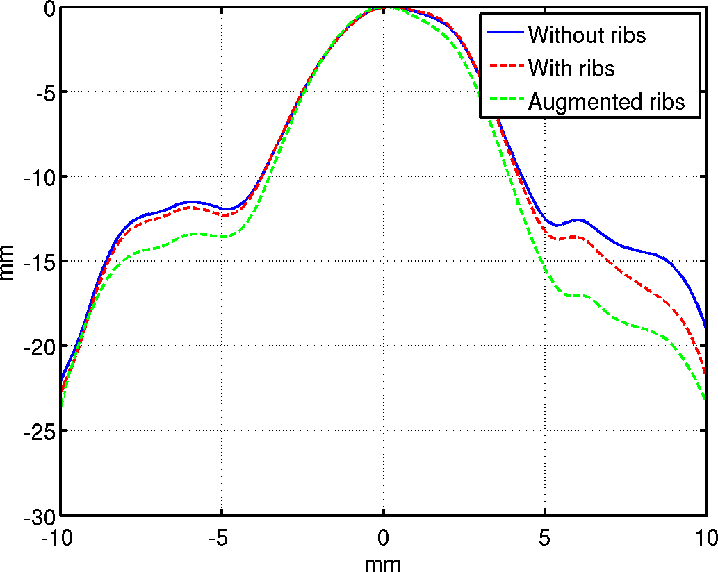
Even though data only from the surface of the human body, at the transducer location, is used to generate the B-mode images, the simulation calculates the acoustic propagation throughout the volume. It is therefore straightforward to determine the imaging beam intensity by integrating the pressure squared at each location in space as a function of time. The beam shape, a fundamental property that predicts image quality in the central elevation plane for the case without ribs (left), with ribs (center), and with augmented ribs (right) at the fundamental (Fig. 4) and second harmonic (Fig. 5) frequencies. The lateral beams for the anatomically correct case is shown in part I of this paper. The lateral beams for the case without ribs and with augmented ribs are not shown here because they are not discernibly different.
The middle and right beams in Figs. 4, 5 exihibit a shadowing effect from the ribs at 30 and 35 mm which is apparent from the drop in intensity. The development of the harmonic energy with propagation can be observed starting at approximately 10mm of depth. The harmonic beam is therefore well developed before it passes in between the ribs, suggesting that the ribs will also have an impact on the transmitted harmonic beam. Qualitatively the ribs appears to have a weak influence on beam shape across the different rib cases, indicating that this is a good acoustical window.
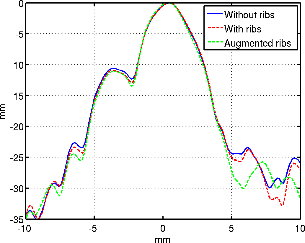
A quantitative assessment of the ribs’ impact is shown by the elevation beamplots (Fig. 6) taken at the focal depth. Overall the harmonic beams (bottom) have lower sidelobes and a lower mainlobe compared to the beams at the fundamental frequency (top). This is consistent with the observed improvements in CNR for the harmonic images in Figs. 2, 3. At the fundamental frequency the case with ribs (dashed red curve) has sidelobes that are 1-2 dB lower than the no rib case (solid blue curve) and the augmented ribs beamplot (dashed green curve) has sidelobes that are 3-5 dB lower and a narrower mainlobe. The beamplots at the harmonic frequency follow a similar trend: reduction of sidelobes and slight reduction in beam width. However this trend is less marked, probably because the narrower harmonic beam passes more easily in between the ribs.
The ribs effectively apodize the beam while maintaining or improving the mainlobe width. The beamplots therefore predict an improvement with the ribs and an even greater improvement with the augmented ribs. This prediction is only partially consistent with trends shown in Figs. 2, 3 where the image quality decreases with the augemented rib case. The beamplots alone are therefore not sufficient to explain the observed image quality metrics.


III-B Phase aberration
The phase aberration, a fundamental parameter for focusing quality, was determined just after the body wall and ribs, at a depth of 37 mm and. It therefore includes the effects of propagation through the near field skin, connective tissue, fat, and muscle. The phase aberration was then measured as the deviation of the beam from it’s ideal spherically focused profile, using an intensity thresholded phase aberration methods described in the companion paper.
| Without ribs | With ribs | Augmented ribs | |
|---|---|---|---|
| Fundamental | 23.4 ns | 23.4 ns | 23.5 ns |
| Harmonic | 15.1 ns | 16.2 ns | 16.2 ns |
The root-mean-square phase aberration for the different configurations, summarized in Table. II. They are consistent with the 21.3 ns experimental reports of the arrival time across a mechanically scanned 2-D aperture for ultrasound propagating through a human chest wall [4]. Furtheremore they are than at the fundamental frequency and at the second harmonic frequncy, indicating that overall aberration has a low impact on the image quality[15]. The harmonic beams are significantly less aberrated than fundamental beams. Nevertheless there is practically no difference in the phase aberration with or without the ribs. For this imaging scenario the differential influence of phase aberration on image quality can therefore be ignored.
III-C Reverberation clutter
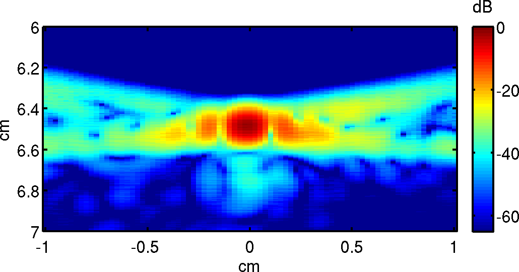
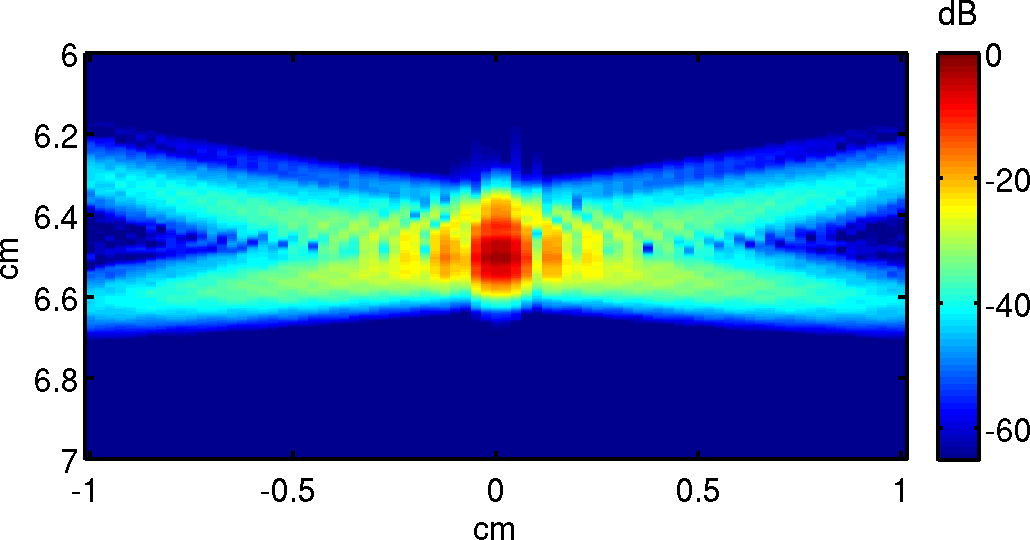
The reverberation clutter was determined with a point spread function analysis [2]. A point target was placed at the focus of a homogeneous material (Fig. 7(a), top) and single focused transmit-receive simulation was used to generate a reference point spread functions (PSF) at the fundamental frequency (Fig. 7(a), middle) and at the harmonic frequency (Fig. 7(a), bottom). In these images the bow-tie shape of the isochronous volume is clearly visible. Within the isochronous volume the signal transmitted by any point on the transducer surface has had time to travel to the point target and back to any other point on the transducer surface. In the region above the PSF the signal has not yet had time to reach the point target and in the region below the signal it has already passed the point target. Overall, the shapes of the fundamental and harmonic PSFs are similar. However, the harmonic PSF is slightly narrower in the lateral dimension and has lower side-lobes than the fundamental PSF, which is consistent with the beamwidths shown in the companion paper (Fig. 7) and with the improvements in image quality observed here (Fig. 2).
| \begin{overpic}[width=52.03227pt]{figures/cmap_psf_lat_homog_reduced} \put(-5.0,170.0){(a)} \put(34.0,45.0){\bf{\color[rgb]{1,1,1}\circle{2.0}}} \put(24.0,60.0){\small{\color[rgb]{1,1,1} point }} \put(23.0,51.0){\small{\color[rgb]{1,1,1} target }} \end{overpic} | \begin{overpic}[width=52.03227pt]{figures/cmap_psf_lat_reduced}\put(-5.0,170.0){(b)} \put(34.0,45.0){\bf{\color[rgb]{1,1,1}\circle{2.0}}} \put(24.0,60.0){\small{\color[rgb]{1,1,1} point }} \put(23.0,51.0){\small{\color[rgb]{1,1,1} target }} \end{overpic} | \begin{overpic}[width=52.03227pt]{figures/cmap_psf_lat_reduced}\put(-5.0,170.0){(c)} \put(30.0,69.0){\small{\color[rgb]{1,1,1} no }} \put(24.0,60.0){\small{\color[rgb]{1,1,1} point }} \put(23.0,51.0){\small{\color[rgb]{1,1,1} target }} \par\end{overpic} | \begin{overpic}[width=52.03227pt]{figures/cmap_psf_lat_reduced}\put(-5.0,170.0){(d)} \put(34.0,45.0){\bf{\color[rgb]{1,1,1}\circle{2.0}}} \put(22.0,69.0){\small{\color[rgb]{1,1,1} (b)-(c) }} \put(24.0,60.0){\small{\color[rgb]{1,1,1} point }} \put(23.0,51.0){\small{\color[rgb]{1,1,1} target }} \par\end{overpic} |
|---|---|---|---|
 |
 |
 |
 |
 |
 |
 |
 |
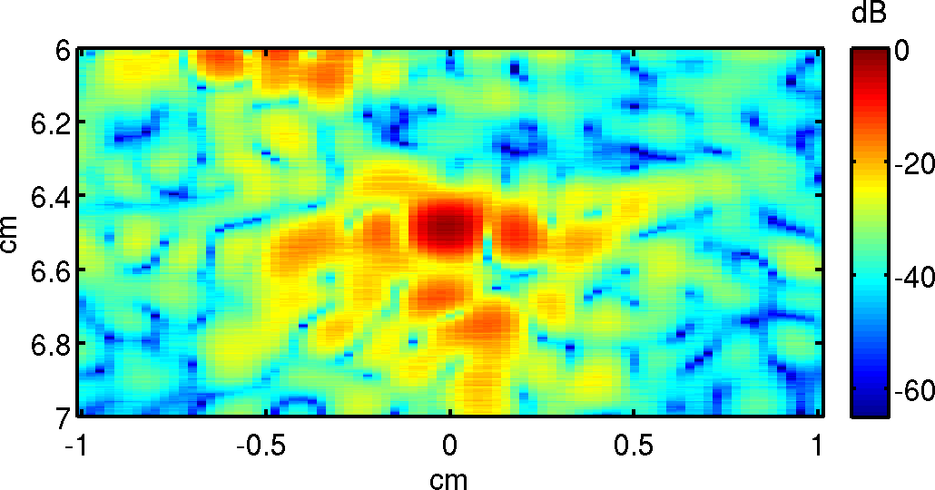
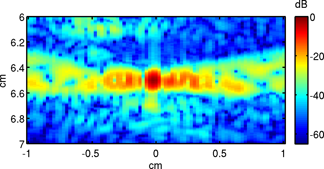
Then the point target was placed in the human body map (Fig. 7(b), top) and the same procedure was used to generate PSFs at the fundamental frequency (Fig. 7(b), middle) and at the harmonic frequency (Fig. 7(b), bottom). Note that unlike the B-mode simulations no additional sub-resolution scatterers were placed in the acoustical maps. The influence of the body wall is apparent from the speckle pattern that surrounds the PSF. This speckle pattern does not come from sub-resolution scatterers near the point target because they were not included in the acoustical maps. Rather the speckle present in the region preceding the PSF arises from multipath reverberation because the signal has not yet had time to travel to the point target and back on a ballistic path. This suggests that reverberation clutter is responsible for the bulk of the signal that degrades the PSF. This hypothesis was tested with the two additional PSF simulations described subsequently.
The speckle has a larger amplitude in the fundamental PSF than in the harmonic PSF, indicating that there is more degradation at the fundamental frequency.
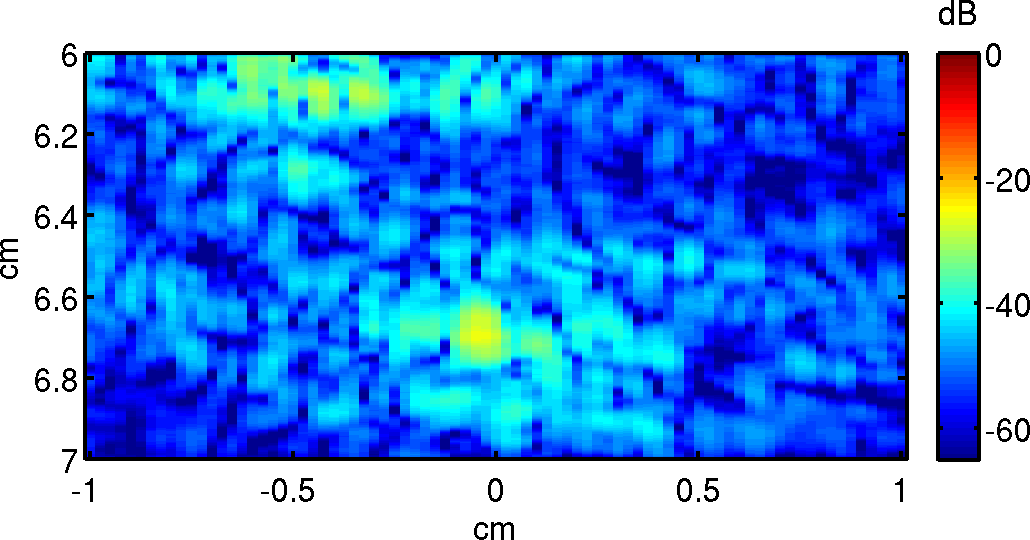
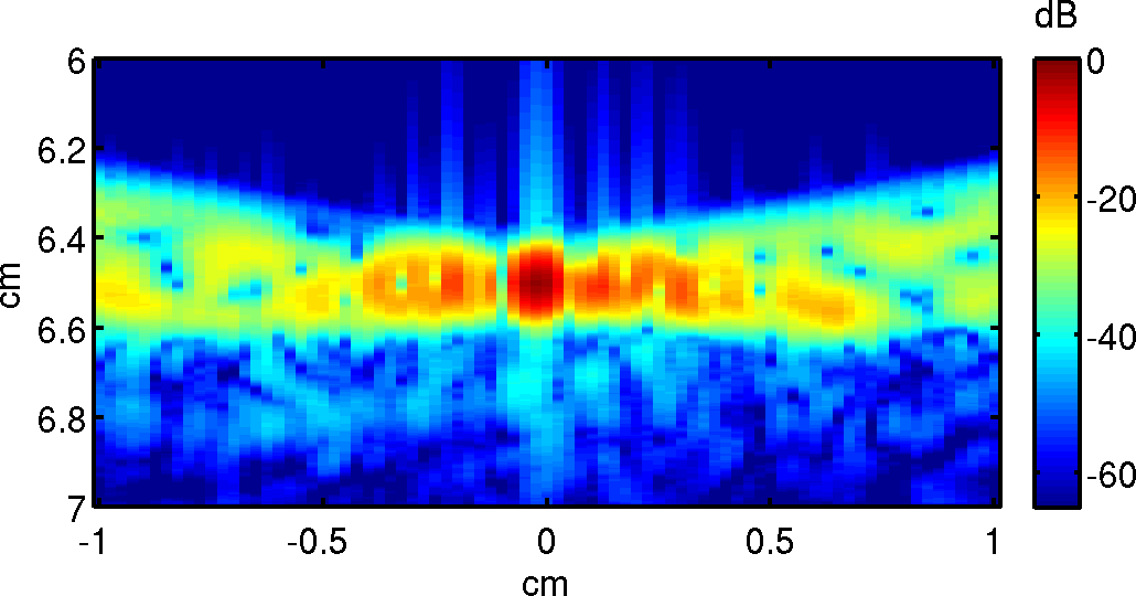
The third PSF was calculated by removing the point target from the acoustical maps of the abdomen (Fig. 7(c), top) and by generating the fundamental (Fig. 7(c), middle) and harmonic PSFs (Fig. 7(c), bottom) based solely on the signal from multipath reverberation clutter. Then the fourth PSF (Fig. 7(d)) was obtained by subtracting the third reverberation clutter PSF from the second full abdominal PSF. This fourth PSF does not have reverberation clutter, however it is still degraded by phase aberration, which appears within the isochronous volume, and by pulse lengthening, which appears following the isochronous volume.
Together the third and fourth PSFs illustrate several qualitative results. Reverberation clutter occurs over a wide spatial extent. The overall amplitude of the reverberation clutter is significantly larger at the fundamental frequency than at the harmonic frequency. Pulse lengthening is more significant at the harmonic frequency than at the fundamental. Phase aberration within the isochronous is also more significant than at the fundamental frequency. This is consistent with results in Table. II where the RMS aberration expressed a fraction of the wavelength is at the fundamental frequency and at the harmonic frequency.
This sequence of PSFs was calculated for the three imaging scenarios. A comparison of the reverberation clutter PSFs for the fundamental frequency (Fig. 8) and harmonic frequncy (Fig. 9) shows how the ribs affect the overall clutter levels in the ultrasound images. Note that the overall clutter level is on a dB scale that is calculated relative to the peak of the abdominal PSF (Fig. 7 column b). The average amplitude of the clutter PSF within the figure for the fundamental frequency without ribs (Fig. 8a) is -35.6 dB. The addition of ribs (Fig. 8b) only slightly increases the clutter levels to -35.4 dB. However in the augmented rib case (Fig. 8c) the clutter levels are -32.7 dB, i.e. 2.9 dB higher.
The harmonic clutter PSFs show a similar trend. The average amplitude of the clutter PSF within the figure for the harmonic frequency without ribs (Fig. 9a) is -51.3 dB. The addition of ribs (Fig. 8b) only slightly increases the harmonic clutter levels to -51.2 dB. However in the augmented rib case (Fig. 8c) the harmonic clutter levels are -48.9 dB, i.e. 2.4 dB higher. These results are summarized in Table II.
| No ribs | Ribs | Augmented ribs | |
|---|---|---|---|
| Fundamental | -35.6 dB | -35.4 dB | -32.7 dB |
| Second harmonic | -51.3 dB | -51.2 dB | -48.9 dB |
The clutter PSFs along with the beamplots can be used to explain the observed B-mode image CNR trends in Fig 2. The ribs act as effective apodizers and reverberators. For the case where the ribs are in their anatomical position there is enough apodization to improve the image quality and not enough reverberation to degrade it. The CNR therefore improves for both the harmonic and fundamental imaging cases. This is in part due to the fact that the harmonic beam is fully developed by the time it reaches the ribs (Fig. 6). When the ribs are placed artificially closer together the apodization improves further, but the reverberation clutter becomes significant and the overall CNR decreases. Thus, although the overall harmonic image quality is better than the fundamental image quality, the image quality trends dictated by body wall’s effect on beam shape and multiple reverberation hold for both frequencies.
IV Summary and conclusion
The image quality for intercostal ultrasound was investigated in terms of beam profile, aberration, and reverberation clutter. For the specific case considered here, which was derived from the three dimensional Visible Human anatomical data set, it was shown that the image quality depended principally on the beam profile and multiple reverberation. Aberration was shown to be quite small, below with respect to the fundamental frequency. The investigation of the beamplots demonstrated that the ribs acted as effective apodizers, which improved the sidelobes. This shows that if the main beam is aimed correctly the side lobes can be blocked by the ribs to obtain an acoustic window that improves the image quality. This interpretation was supported by the B-mode images calculated with the transmit-receive Fullwave simulations which showed an appreciable increase in CNR at both the fundamental and harmonic frequencies. This illustrates the importance for a sonographer to find an appropriate acoustic window.
Then, by changing only one variable, i.e. the rib placement, and by maintaining all other parameters of the body wall composition, such as fat and connective tissue distribution constant, it was shown how a different rib placement can degrade the image quality. In particular the ribs were placed closer together by just a few millimiters which had the effect of further improving the beamplot. However the CNR measured with the transmit-receive Fullwave simulations which showed an appreciable decrease in CNR at both the fundamental and harmonic frequencies. It was thus clear that the beamplot and aberration alone was not sufficient to predict image quality in this case. Multiple reverbration was therefore calculated using a point spread function analysis that can separate reverberation from multi-path scattering from other sources of image degradation. It was shown that when the ribs were artificially placed closer the degradation from multiple reverberation decreased the image quality, negating any gains from the improved beam shape. In conclusion this multiparameter analysis of a specific intercostal imaging scenario demonstrates the interplay of two conventional image quality metrics, aberration and beam shape, and a relatively under-appreciated image quality metric, multiple reverberation. To estimate the relative contribution of these metrics on the image quality the full three dimensional wave propagation in the human body had to be modeled. The applications of this simulation tool and image quality analysis are not limited to intercostal imaging and can be applied to other imaging configurations and to other areas of the body.
References
- [1] T. L. Szabo and P. A. Lewin, “Ultrasound transducer selection in clinical imaging practice,” Journal of Ultrasound in Medicine, vol. 32, no. 4, pp. 573–582, 2013.
- [2] G. Pinton, J. Dahl, and G. Trahey, “Sources of image degradation in fundamental and harmonic ultrasound imaging: A nonlinear, full-wave, simulation study,” IEEE Trans. Ultrason. Ferroelectr. Freq. Control, 2011.
- [3] G. Pinton, J. Dahl, S. Rosenzweig, and G. Trahey, “A heterogeneous nonlinear attenuating full-wave model of ultrasound,” Ultrasonics, Ferroelectrics and Frequency Control, IEEE Transactions on, vol. 56, no. 3, pp. 474–488, 2009.
- [4] L. M. Hinkelman, T. L. Szabo, and R. C. Waag, “Measurements of ultrasonic pulse distortion produced by human chest wall,” The Journal of the Acoustical Society of America, vol. 101, no. 4, pp. 2365–2373, 1997.
- [5] J.-F. Aubry, M. Pernot, F. Marquet, M. Tanter, and M. Fink, “Transcostal high-intensity-focused ultrasound: ex vivo adaptive focusing feasibility study,” Physics in medicine and biology, vol. 53, no. 11, p. 2937, 2008.
- [6] M. Fink, “Time reversal of ultrasonic fields – Part I: Basic principles,” IEEE Trans. Ultrason. Ferroelectr. Freq. Control, vol. 39, no. 5, pp. 555–566, 1992.
- [7] S. Bobkova, L. Gavrilov, V. Khokhlova, A. Shaw, and J. Hand, “Focusing of high-intensity ultrasound through the rib cage using a therapeutic random phased array,” Ultrasound in medicine & biology, vol. 36, no. 6, pp. 888–906, 2010.
- [8] J. R. Ballard, A. J. Casper, Y. Wan, and E. S. Ebbini, “Adaptive transthoracic refocusing of dual-mode ultrasound arrays,” IEEE Transactions on Biomedical Engineering, vol. 57, no. 1, pp. 93–102, 2010.
- [9] V. Khokhlova, S. Bobkova, and L. Gavrilov, “Focus splitting associated with propagation of focused ultrasound through the rib cage,” Acoustical physics, vol. 56, no. 5, pp. 665–674, 2010.
- [10] P. Gélat, G. Ter Haar, and N. Saffari, “Modelling of the acoustic field of a multi-element hifu array scattered by human ribs,” Physics in medicine and biology, vol. 56, no. 17, p. 5553, 2011.
- [11] P.-C. Li, S. W. Flax, E. S. Ebbini, and M. O’Donnell, “Blocked element compensation in phased array imaging,” IEEE transactions on ultrasonics, ferroelectrics, and frequency control, vol. 40, no. 4, pp. 283–292, 1993.
- [12] M. Jakovljevic, G. F. Pinton, J. J. Dahl, and G. E. Trahey, “Blocked elements in 1-d and 2-d arrays—part i: Detection and basic compensation on simulated and in vivo targets,” IEEE Transactions on Ultrasonics, Ferroelectrics, and Frequency Control, vol. 64, no. 6, pp. 910–921, 2017.
- [13] M. Jakovljevic, N. Bottenus, L. Kuo, S. Kumar, J. J. Dahl, and G. E. Trahey, “Blocked elements in 1-d and 2-d arrays part ii: Compensation methods as applied to large coherent apertures,” IEEE Transactions on Ultrasonics, Ferroelectrics, and Frequency Control, 2017.
- [14] V. Spitzer, M. Ackerman, A. Scherzinger, and D. Whitlock, “The visible human male: a technical report,” Journal of the American Medical Informatics Association, vol. 3, no. 2, pp. 118–130, 1996.
- [15] J. W. Goodman, Introduction to Fourier Optics. McGraw-Hill, 1996.