Nonreciprocal Second-Harmonic Generation in Few-Layer Chromium Triiodide
Abstract
It is of fundamental importance but challenging to simultaneously identify atomic and magnetic configurations of two-dimensional van der Waals materials. In this work, we show that the nonreciprocal second-harmonic generation (SHG) can be a powerful tool to answer this challenge. Despite the preserved lattice inversion symmetry, the interlayer antiferromagnetic order and spin-orbit coupling generate enhanced SHG in PT-symmetric bilayer chromium triiodide (CrI3). Importantly, the in-plane polarization-resolved SHG is sensitive to subtly different interlayer structures that cannot be told by linear optical spectra. Beyond bilayer, we further predict that the intensity and angle-resolved SHG can be employed to identify both interlayer atomic and magnetic configurations of trilayer CrI3. Our first-principles results agree with available measurements and show the potential of SHG as a non-contacting approach to explore correlations between interlayer structures and magnetic orders of emerging ultra-thin magnetic materials.
I Introduction
Antiferromagnetic (AFM) materials could represent the future of spintronic applications due to many advanced features, such as robustness against the magnetic-field perturbation, ultrafast dynamics, and large magnetoresistance effects Baltz et al. (2018); Němec et al. (2018); Wang et al. (2018). For example, experimental demonstrations of the electrical switching and detection of the Neel order of AFM CuMnAs open a new avenue towards memory devices based on antiferromagnets Wadley et al. (2016). However, simultaneously identifying both AFM order and atomic structures is difficult for conventional magnetometry approaches Němec et al. (2018). This challenge is more serious for emerging two-dimensional (2D) van der Waals (vdW) magnets. Although neutron diffraction plays a major role in probing magnetic orders for bulk crystals Shull et al. (1951), it is not applicable for epitaxial or exfoliated ultra-thin structures because of substrate effects. To date magneto-optics effects, such as the magneto-optics Faraday and Kerr effect, have been widely used for detecting the Neel order of 2D magnets. Seyler et al. (2018); Chen et al. (2019); Mak et al. (2019) Meanwhile, the terahertz radiation, which predominantly interacts with low-energy excitations, is an excellent tool for detecting the spin-wave excitation in magnetic materials. Nevertheless, both probing tools cannot tell the subtle interlayer structural information, which is, however, crucial for studying vdW materials because their magnetic orders are strongly correlated with interlayer configurations. Sivadas et al. (2018); Li et al. (2019); Jang et al. (2019)
Second-harmonic generation (SHG) is a powerful tool to discriminate the magnetic point or space groups that are indistinguishable by the above diffraction methods Fiebig et al. (2000, 2005); Ju et al. (2009); Lucking et al. (2018). Particularly, significant nonlinear optical (NLO) responses were reported in bilayer AFM chromium triiodide (CrI3) Sun et al. (2019); Zhang et al. (2019), indicating potentially unique SHG of layered magnetic materials. Beyond studying CrI3, which exhibits a considerable magneto-optics effect Sun et al. (2019); Gudelli and Guo (2019); Zhang et al. (2019); Wu et al. (2019), SHG is also capable in studying those AFM materials that have rather weak magneto-optics effects Wang et al. (2006). This advantage broadens the applicable range of SHG. Correspondingly, a systematical theoretical study of SHG and its relationship with interlayer atomic and magnetic orders is crucial for understanding available measurements and motivating further efforts to explore complex symmetries of 2D vdW structures.
In this work, we focus on SHG of bilayer and trilayer CrI3 using first-principles calculations. Despite the lattice inversion symmetry, the interlayer AFM order and spin-orbit coupling (SOC) of bilayer CrI3 break both inversion and time-reversal symmetries of magnetic space groups, leading to non-zero SHG signals. We further find that the polarization-resolved azimuthal SHG is determined by the space group of parent lattices and it can be utilized to distinguish the subtle differences between interlayer structures. For trilayer CrI3, our calculation shows that SHG can tell both interlayer atomic and magnetic orders, giving rise to a powerful tool to efficiently explore symmetries of ultra-thin 2D materials.
The remainder of this work is organized as follows: In Section II, we present the calculation methods and simulation details. In Section III, the lattice structures of CrI3 and linear optical properties are introduced. In Section IV, we discuss the origin and mechanism of nonvanishing SHG in PT-symmetric systems. In Section V, the SHG susceptibility of bilayer CrI3 is obtained by first-principles simulations. In Section VI, we show the polarization-resolved SHG and how to utilize it to distinguish different interlayer structures of bilayer CrI3. In Section VII, we expand the SHG study to trilayer CrI3 and show how to tell the interlayer atomic and magnetic configurations. Finally, the results are summarized in the conclusion section.
II Calculation details
We calculate the structural and electronic properties of CrI3 by density functional theory (DFT) within the generalized gradient approximation (GGA) using the Perdew-Burke-Ernzerhof (PBE) functional Perdew et al. (1996), which is implemented in the Vienna ab initio simulation package (VASP) Kresse and Furthmüller (1996); Kresse and Joubert (1999). The vdW interactions are included through the DFT-D3 method with zero dampings Grimme et al. (2010, 2011). The converged charge densities and wavefunctions are obtained in plane-wave basis with an energy cutoff of 450 eV. SOC is included in all simulations. To deal with localized orbitals of Cr atoms, the DFT+U scheme is employed with eV Sivadas et al. (2018). Our main conclusions of SHG are not sensitive to the value of U.
A k-point sampling of 32321 is used to obtain converged optical susceptibilities. The linear optical response is calculated based on single-particle interband transitions Guo et al. (2004); Wu et al. (2019); Song et al. (2020); Wang and Qian (2017). DFT is known for underestimating band gaps and neglecting many-electron corrections, such as exciton effects Fei et al. (2020); Chan et al. (2019). However, in this study, we particularly focus on characters of polarization dependencies of SHG according to symmetries of materials. Therefore, we do not include excitonic effects, and the band gap is corrected by rigidly shifting the DFT band gap to meet the observed lowest-energy exciton peak Wu et al. (2019). Within this approximation, the profiles of calculated NLO spectra may not be accurate, but the polarization-symmetry dependence of optical responses shall be reliable due to that electron-hole (e-h) interactions do not break any existing structural/magnetic symmetry. For SHG calculations, we follow the framework of perturbation theory based on the polarization operator Hughes and Sipe (1996) by using the ArchNLO package. Song et al. (2020) We include 120 conduction bands for each layer of CrI3 for converged SHG spectra. Finally, we only consider in-plane optical responses because of the local-field effect that quenches off-plane electric fieldAndo (1997); Machón et al. (2002); Marinopoulos et al. (2003).
III Atomic structures and linear optical responses of bilayer AFM chromium triiodide
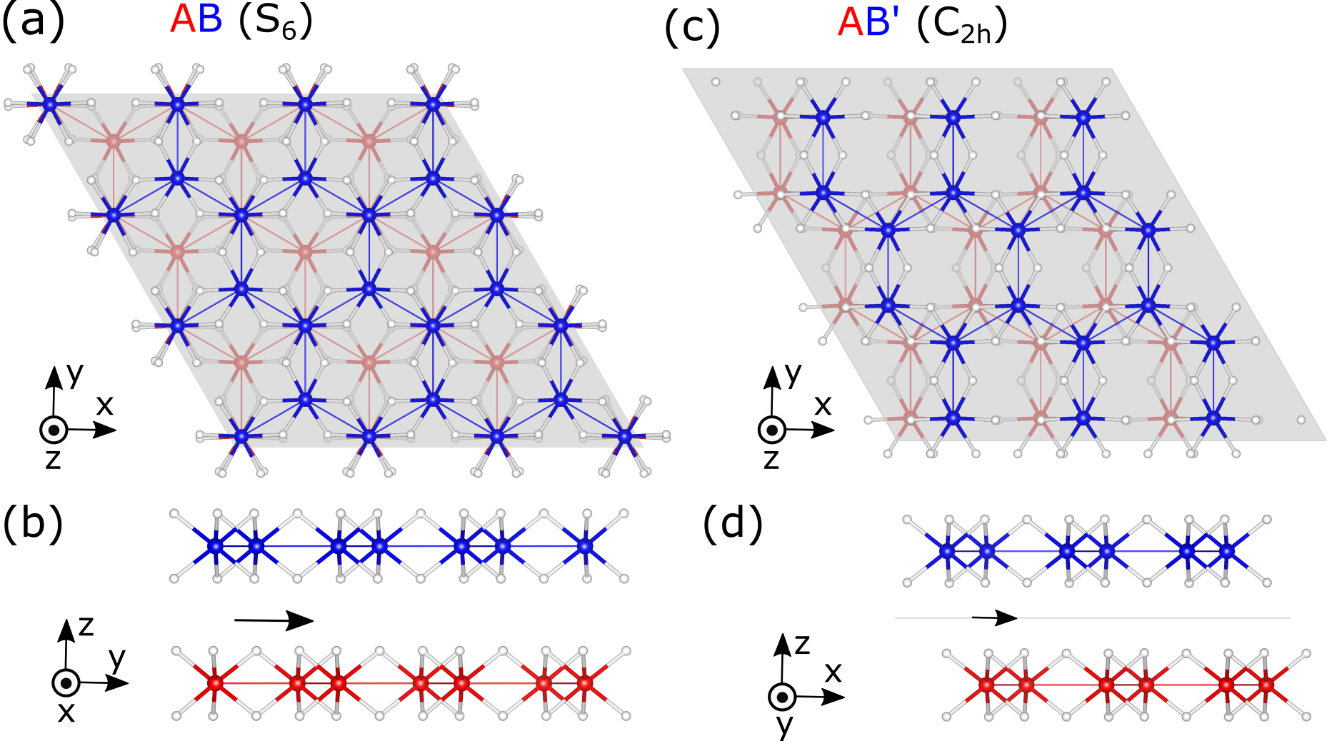
Bulk CrI3 is a layered vdW magnetic material Handy and Gregory (1952). Each layer of CrI3 owns hexagonal lattices in a point group, in which magnetic Cr atoms form a honeycomb structure and each Cr atom is surrounded by six I atoms. A unit cell of bulk CrI3 can be obtained by stacking three monolayers following the ABC-Bernal configuration with the same interlayer translation. There are two observed interlayer structures McGuire et al. (2015). One is formed by a interlayer shift, and it is observed at temperature below 210 K, called the low-temperature (LT) structure. The other one is formed by a interlayer shift, and it is observed at temperature above 210 K, called the high-temperature (HT) structure McGuire et al. (2015); Jiang et al. (2019).
The corresponding bilayer structures and symmetry groups based these two bulk phases are presented in Figs. 1 (a)-(d), in which the AB stacking style is from the bulk LT phase while the AB′ stacking style is from the bulk HT phase. In this work, we mainly focus on the interlayer AFM order because of two reasons: 1) the interlayer AFM order has been widely observed in intrinsic 2D samples Huang et al. (2017); 2) the inversion symmetry is preserved in FM bilayer CrI3, and only the AFM order exhibits non-zero SHG.
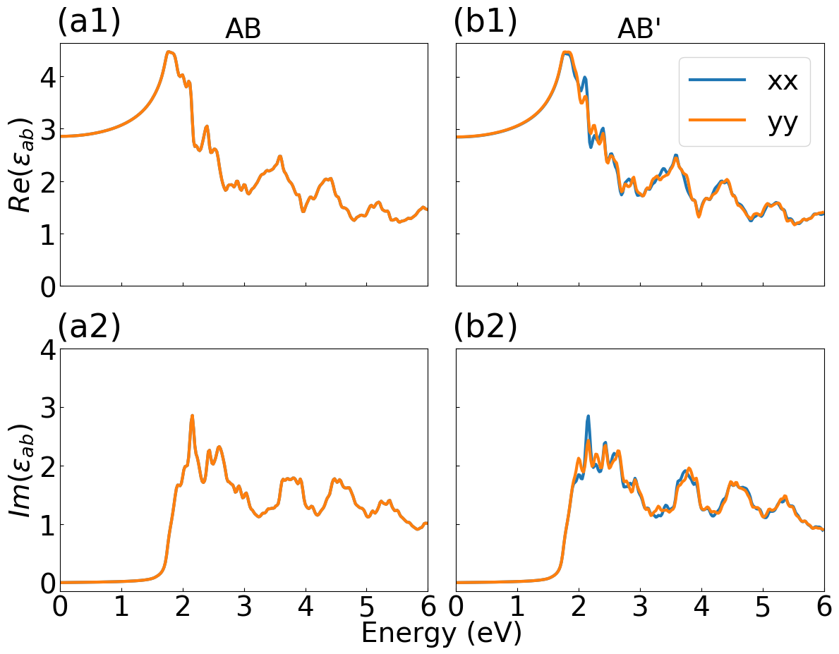
The DFT-calculated real and imaginary parts of the linear dielectric function are plotted in Fig. 2 for the AB and AB′ interlayer structures, respectively. Both AB and AB′ interlayer structures exhibit nearly identical linear dielectric responses, except for a few minor differences. The AB stacking shows a perfectly isotropic linear dielectric function, where the and components are the same. This isotropy is essentially decided by its point group. On the other hand, the spectra of the AB′ stacking exhibit a minor anisotropy because of its lower-symmetric point group. However, this difference is too small to be detected in practical linear optical spectra. Needless to say that the linear dielectric function may not be an efficient way to tell interlayer structures of bilayer CrI3.
IV Origin of SHG in parity-time symmetric AFM systems
Before presenting the first-principles SHG simulation results, it is necessary to introduce general expressions and discuss the origin of non-zero SHG signals in interlayer AFM vdW systems, which keep the parity-time (PT) symmetry.
Following previous works, Hughes and Sipe (1996); Aversa and Sipe (1995) the SHG susceptibility can be generally expressed as
| (1) |
Specifically, the interband transitions at the same crystal momentum contribute to
| (2) |
The modulation of the linear susceptibility due to intraband motions of electrons contributes to
| (3) |
Finally, the term describing the modification by the polarization energy associated with interband motions contributes to
| (4) |
In Eq. 14, we define the momentum matrix element, , as the transition between two states and at the same point, and the position matrix element is defined by if or 0 if . Meanwhile, and ( is the electron mass).
It is known that the SHG response is zero in centro-symmetric materials if time-reversal symmetry is preserved. This can be understood from the above formulas, in which the and terms are odd under inversion symmetry. As a result, their integrations over reciprocal space are zero. However, if considering the magnetic order, the inversion symmetry of the magnetic space group may be broken even with a preserved lattice inversion symmetry, giving hope to non-zero SHG.
In both AB and AB′ AFM bilayer CrI3, the lattices own the inversion symmetry. However, because the space inversion operator cannot reverse the spin-degree freedom, the inversion symmetry in the magnetic space group is broken. Interestingly, this symmetry breaking itself does not guarantee non-zero SHG. Particularly, due to PT symmetry, the spin-up and spin-down band structures are degenerated, and they are symmetric in reciprocal space because of the spin-rotation symmetry Mong et al. (2010). For example, Fig. 3 (a) shows this symmetric band structure of AFM AB bilayer CrI3. As a result, the SHG response is zero because the intraband group velocity is odd in reciprocal space due to these symmetric band structures.
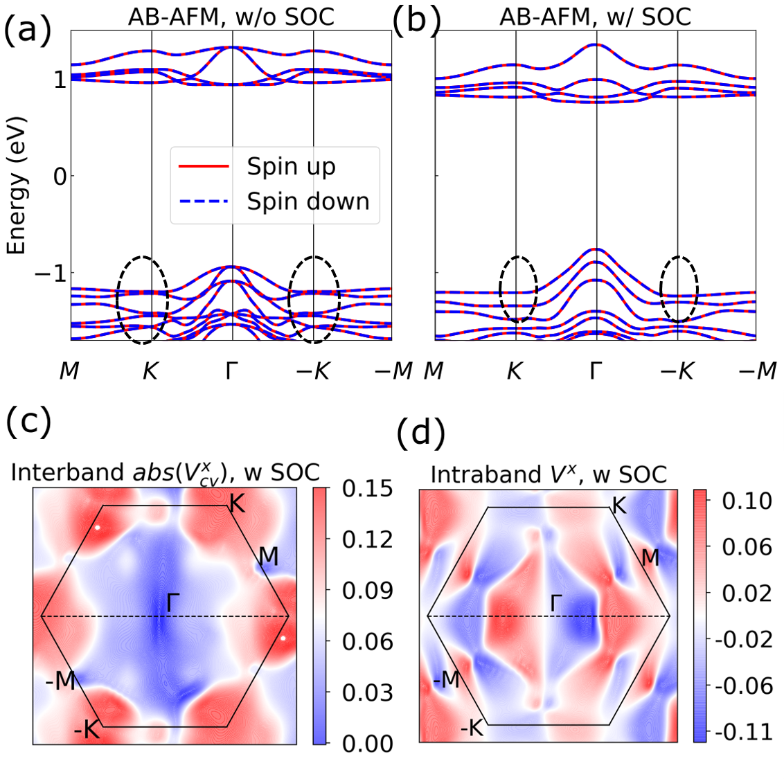
Fortunately, SOC is known to be strong in CrI3, and it breaks the spin-rotation symmetry Zhang et al. (2019); Fei et al. (2019). To demonstrate the symmetry breaking, we plot the band structure with SOC included for the AFM AB bilayer structure in Fig. 3 (b). Black dotted circles are marked around and points to address the broken symmetric band structures by SOC. Moreover, as shown in Figs. 3 (c) and (d), the parity symmetries of both interband and intraband velocity matrices, which are calculated by first-principles simulations, are also broken with SOC included. Because the strength of SHG susceptibility is proportional to the integral of transition intensity and velocity matrices in reciprocal space, these asymmetric velocity matrices indicate non-zero SHG.
V SHG susceptibility of bilayer AFM chromium triiodide
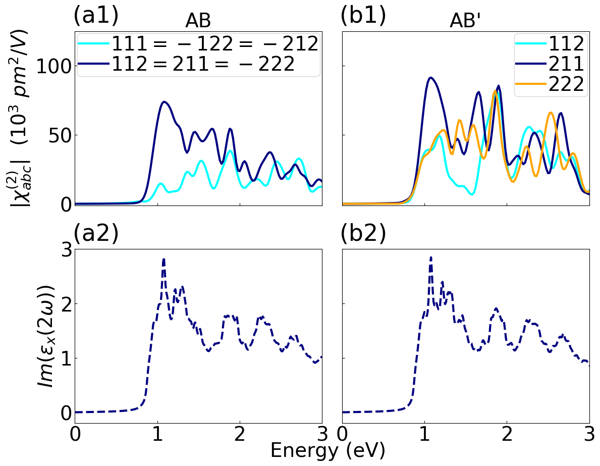
The in-plane components of SHG susceptibility tensor have been calculated, and those nonzero components are plotted in Figs. 4 (a1) and (b1) for AFM AB and AB′ bilayer CrI3, respectively. Unlike the similar linear optical spectra in Fig. 2, those NLO SHG spectra exhibit significant differences between two interlayer structures. Figure 4 (a1) presents that there are two non-zero independent SHG spectra for the AB interlayer structure, and each contains three degenerated components. The dark-blue line represents the absolute SHG susceptibility elements of degenerated = = . while the cyan line represents those of degenerated = = . In the AB′ stacking case shown in Fig. 4 (b1), there are three non-zero independent SHG spectra, , , and because of the lower symmetry.
To help analyze the spectra of SHG susceptibilities, we plot the double-frequency linear optical absorption spectra ()) in Figs. 4 (a2) and (b2) of both interlayer structures. This is an approximation to only consider two-photon processes with identical energy, reflecting the double-photon resonance. Song et al. (2020); Wang and Guo (2015) Interestingly, the profiles of double-resonant spectra and the significant component of SHG spectra are similar. For example, the first significant peak in the spectrum of is at 1.1 eV. It agrees well with the first peak of , as shown in Fig. 4 (a2). Such a phenomenon indicates that main features (peaks) of SHG spectra are dominated by double-resonance processes. This is consistent with previous studies on transition-metal dichalcogenides and hybrid halide perovskitesSong et al. (2020); Wang and Guo (2015).
It is important to notice that the amplitude of SHG susceptibility of bilayer PT-symmetric CrI3 structures is significant. As shown in Fig. 4, their values can reach 7104 . These magnetic-ordering induced SHG signals are comparable to those of monolayer MoS2 (1104 6104 ), which owns a non-centrosymmetric structure Wang and Qian (2017); Grüning and Attaccalite (2014); Li et al. (2013a); Kumar et al. (2013a); Malard et al. (2013a); Trolle et al. (2014). Moreover, the SHG signals of bilayer AFM CrI3 are about one order of magnitude larger than those of a hexagonal boron nitride (h-BN) sheet (0.1104 0.6104 ) Wang and Qian (2017); Grüning and Attaccalite (2014); Li et al. (2013a). This enhanced SHG agrees with recent measurements of bilayer CrI3 Sun et al. (2019).
VI Polarization-resolved SHG of bilayer chromium triiodide
Although SHG spectra of AB and AB′ interlayer structures are different, it is not convenient to directly use them to identify structures because this approach needs data of a wide range of frequencies. A more efficient approach is to measure the polarization-resolved SHG at a fixed frequency of the excitation beam Sun et al. (2019); Romijn et al. (2018); Yang et al. (2019). In the following, we adopt the popular experimental setup and give the angle-resolved SHG polarization of bilayer AFM CrI3 Sun et al. (2019); Wang and Qian (2017). The response direction is set to be parallelly (co-linearly) or perpendicularly (cross-linearly) polarized with respect to the azimuthal polarization of incident beam. Meanwhile, we keep these two directions rotating together within the xy plane.
The electric field of incident light is given by
| (5) |
in which donate laboratory coordinates, and represents the azimuthal rotational angle. and are Cartesian components of the electric field of incident light.
In this work, we assume a normal incidence and focus on the in-plane detection and excitation. The response of in-plane SHG polarization is given by
| (6) |
presents components of SHG tensors, in which the subscripts (1,2, and 3) donate , , and . The first subscript is the response direction, and the last two are the excitation directions. and are induced polarizations by excitation electric fields.
Finally, the parallel (perpendicular) SHG polarization can be defined as
| (7) |
in which () indicates the parallel (perpendicular) polarization component.
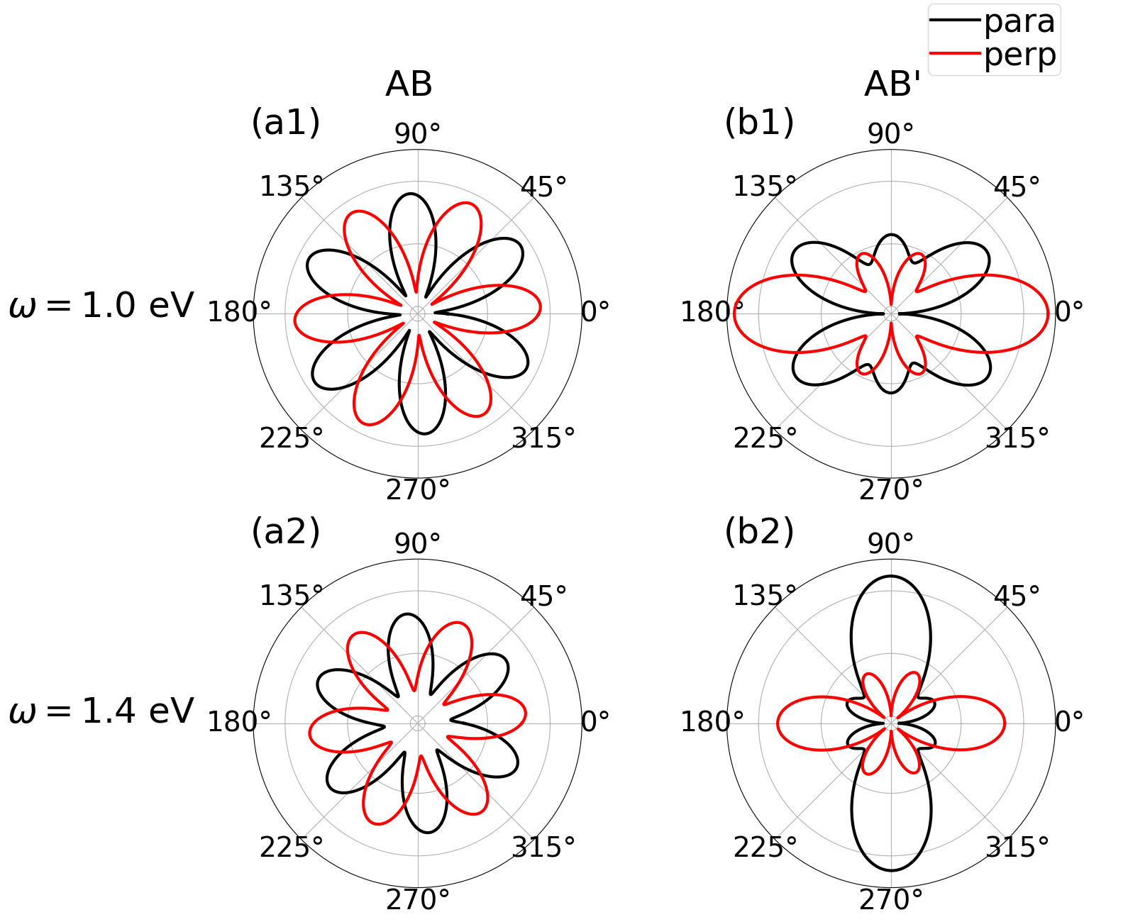
Figure 5 shows the polarization dependence of SHG responses for AB and AB′ stackings of AFM bilayer CrI3 at two fixed frequencies (=1.0 eV and 1.4 eV). Unlike linear optical responses shown in Fig. 2, the in-plane polarization-resolved SHG is sensitive to the subtle interlayer structures. In Figs. 5 (a1) and (a2) of the AB stacking AFM bilayer CrI3, both para and perp SHG signals exhibit a 6-fold sunflower-like pattern. On the contrary, for the AB′ stacking, the SHG patterns exhibit a butterfly-like two-fold mirror symmetry, as shown in Figs. 5 (b1) and (b2).
These patterns are essentially decided by the symmetry groups of interlayer structures. For the AB-type bilayer which owns a high-symmetry point group, the 3-fold rotation symmetry results in: as well as (indicated in Fig. 4 (a1)). We can substitute these formulas into Eqs. 57. The parallel and perpendicular SHG susceptibilities are reduced to be
| (8) |
Therefore, the absolute value of parallel and perpendicular polarizations exhibit a 6-fold symmetry due to the and terms. Such a 6-fold SHG pattern has also been observed in similarly three-fold-symmetry structures, such as monolayer MoS2 and -BN Wang and Qian (2017); Yang et al. (2019); Kumar et al. (2013b); Malard et al. (2013b); Li et al. (2013b); Hsu et al. (2014).
For the AB′ stacking structure with a symmetry, the distinct non-zero in-plane elements of the SHG susceptibility tensor are , , and , as shown in Fig. 4 (b1). In this case, the parallel and perpendicular SHG polarization components are reduced to be
| (9) |
These formulas of polarization components are complicated, leading to the more anisotropic polarization-resolved SHG. However, the absolute values are even-parity according to the angle (), resulting in a two-fold mirror symmetry, as shown in Figs. 5 (b1) and (b2). These characteristic mirror-symmetry patterns of the polarization-resolved SHG have been also observed in monolayer group-IV monochalcogenides Wang and Qian (2017) because of their same point group.
These distinct features of polarization-resolved SHG in Fig. 5 make it easy to distinguish interlayer structures of bilayer AFM CrI3. In fact, the similarly polarization-resolved SHG shown in Figs. 5 (b1) and (b2) were observed in fabricated bilayer CrI3 with 1000-nm incident light, confirming the AB′ (HT) interlayer structure Sun et al. (2019). This observed AB′ (HT) bilayer is surprising because the structural phase transition temperature of bulk CrI3 is around 210 K McGuire et al. (2015), which is substantially higher than the temperature (5 K) measuring SHG of bilayer structures. It will be valuable to explore the fundamental reason for the preserved HT phase of ultra-thin CrI3 structures at low temperatures.
VII Linear optical responses and SHG of trilayer chromium triiodide
We focus on two stable interlayer configurations, i.e., the ABA and AB′A stacking styles of trilayer CrI3. Unlike bilayer, both FM and AFM orders break the inversion symmetry of the magnetic group of trilayer CrI3, resulting in non-zero SHG. It is worth mentioning that, although most available measurements observed an interlayer AFM order in few-layer CrI3, a few recent studies show that external factors, such as pressure, can switch the interlayer magnetic ordering efficiently Li et al. (2019). Therefore, we will calculate SHG of both interlayer AFM and FM orders of trilayer structures.
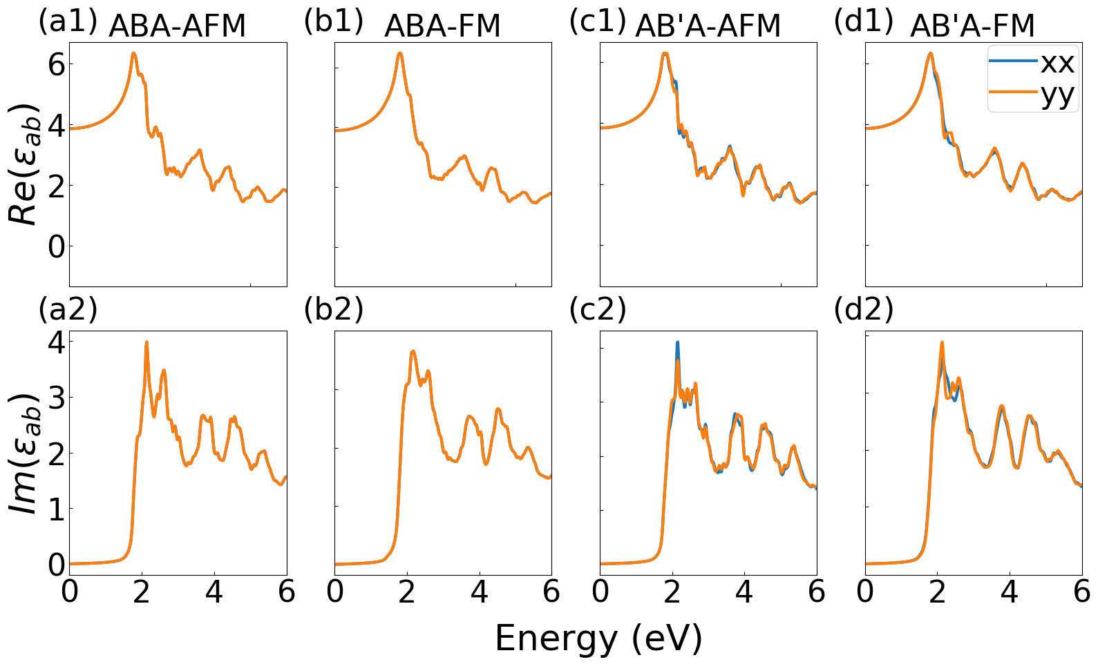
Figure 6 presents the real and imaginary parts of the linear dielectric function of ABA and AB′A configurations with FM and AFM orders, respectively. Like those of bilayer structures, the linear optical spectra of trilayer CrI3 are nearly identical for different interlayer structures and magnetic orders. Because of the lower symmetry of the AB′A interlayer structure, its linear spectra are slightly anisotropic. Unfortunately, these minor differences may not be significant enough to identify structural and magnetic orders for trilayer CrI3.
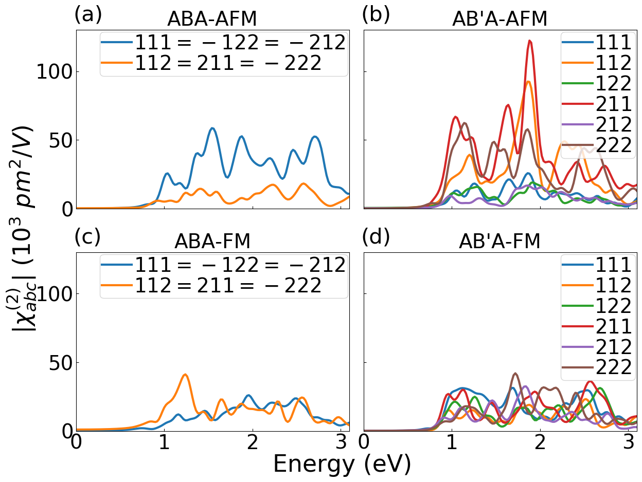
Figures 7 (a)-(d) presents the SHG spectra of trilayer CrI3 with different interlayer structures and magnetic orders. As expected, interlayer magnetic and atomic configurations strongly affect SHG responses. The ABA stacking style has two independent components for both FM and AFM, which are similar with the bilayer case shown in Fig. 4 (a1), indicating a good preservation of symmetries. The AB′A stacking style has six independent non-zero components, due to its lower symmetry. Other than the different profiles of SHG spectra, we can observe that the spectra of AFM structures have more significant peaks and their average SHG intensities are also higher than those of FM structures. This may provide an opportunity to identify magnetic orders of trilayer CrI3.
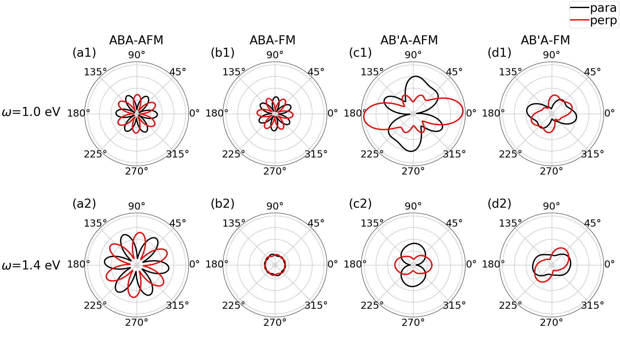
Following the same analysis stated in Section VI, we have further calculated the polarization-resolved SHG patterns of trilayer CrI3, which are plotted in Fig. 8. Two typical excitation frequencies (=1.0 eV and 1.4 eV) are considered in these figures. In these angle-resolved cases, the SHG polarization is more sensitive to the interlayer atomic structures than the magnetic order. For example, for the ABA stacking style, both AFM and FM orders exhibit a 6-fold sunflower-like pattern, which is similar to the case of AB stacked bilayer. For the AB′A stacking style, both FM and AFM orders exhibit distorted butterfly-like patterns, which are similar to the bilayer AB′ case but with a lower symmetry. We also notice that the intensity of SHG polarizations of the AFM order is usually stronger than those of the FM order. This is consistent with the observations of Fig. 7. As a result, the polarization pattern of SHG is effective to tell the crystal structures while its intensity may be useful to tell the magnetic order.
VIII Conclusion
In summary, we have shown that the nontrivial AFM order and SOC break the inversion symmetry and lead to enhanced SHG signals in PT-symmetric bilayer CrI3. Different patterns of polarization-resolved azimuthal SHG can be utilized to distinguish the AB and AB′ interlayer structures. We further expand this approach to discover both magnetic and interlayer structures of trilayer CrI3. The overall intensity of SHG signals can be used to identify magnetic orders, and the polarization-resolved SHG is effective to distinguish interlayer crystal structures. Our calculation provides understandings of recent measurements and sheds light on using nonlinear light-matter interactions to explore atomic and magnetic structures of ultra-thin 2D vdW materials.
Acknowledgements.
This work is supported by the National Science Foundation (NSF) CAREER grant No. DMR-1455346, NSF EFRI2DARE-1542815, and the Air Force Office of Scientific Research (AFOSR) grant No. FA9550-17-1-0304. The computational resources are provided by the Stampede of Teragrid at the Texas Advanced Computing Center (TACC) through XSEDE.References
- Baltz et al. (2018) V. Baltz, A. Manchon, M. Tsoi, T. Moriyama, T. Ono, and Y. Tserkovnyak, Reviews of Modern Physics 90, 015005 (2018).
- Němec et al. (2018) P. Němec, M. Fiebig, T. Kampfrath, and A. V. Kimel, Nature Physics 14, 229 (2018).
- Wang et al. (2018) Z. Wang, I. Gutiérrez-Lezama, N. Ubrig, M. Kroner, M. Gibertini, T. Taniguchi, K. Watanabe, A. Imamoğlu, E. Giannini, and A. F. Morpurgo, Nature communications 9, 1 (2018).
- Wadley et al. (2016) P. Wadley, B. Howells, J. Elezny, C. Andrews, V. Hills, R. P. Campion, V. Novak, K. Olejnik, F. Maccherozzi, S. S. Dhesi, S. Y. Martin, T. Wagner, J. Wunderlich, F. Freimuth, Y. Mokrousov, J. Kune, J. S. Chauhan, M. J. Grzybowski, A. W. Rushforth, K. W. Edmonds, B. L. Gallagher, and T. Jungwirth, Science 351, 587 (2016).
- Shull et al. (1951) C. G. Shull, W. Strauser, and E. Wollan, Physical Review 83, 333 (1951).
- Seyler et al. (2018) K. L. Seyler, D. Zhong, D. R. Klein, S. Gao, X. Zhang, B. Huang, E. Navarro-Moratalla, L. Yang, D. H. Cobden, M. A. McGuire, et al., Nature Physics 14, 277 (2018).
- Chen et al. (2019) W. Chen, Z. Sun, Z. Wang, L. Gu, X. Xu, S. Wu, and C. Gao, Science 366, 983 (2019).
- Mak et al. (2019) K. F. Mak, J. Shan, and D. C. Ralph, Nature Reviews Physics 1, 646 (2019).
- Sivadas et al. (2018) N. Sivadas, S. Okamoto, X. Xu, C. J. Fennie, and D. Xiao, Nano letters 18, 7658 (2018).
- Li et al. (2019) T. Li, S. Jiang, N. Sivadas, Z. Wang, Y. Xu, D. Weber, J. E. Goldberger, K. Watanabe, T. Taniguchi, C. J. Fennie, et al., Nature materials 18, 1303 (2019).
- Jang et al. (2019) S. W. Jang, M. Y. Jeong, H. Yoon, S. Ryee, and M. J. Han, Phys. Rev. Materials 3, 031001 (2019).
- Fiebig et al. (2000) M. Fiebig, D. Fröhlich, K. Kohn, T. Lottermoser, V. Pavlov, R. Pisarev, et al., Physical review letters 84, 5620 (2000).
- Fiebig et al. (2005) M. Fiebig, V. V. Pavlov, and R. V. Pisarev, JOSA B 22, 96 (2005).
- Ju et al. (2009) S. Ju, T.-Y. Cai,C.-I. Wei, and G.-Y. Guo, Opt. Lett. 34, 3860 (2009).
- Lucking et al. (2018) M. Lucking, K. Beach, and H. Terrones, Sci. Rep. 8, 10118 (2018).
- Sun et al. (2019) Z. Sun, Y. Yi, T. Song, G. Clark, B. Huang, Y. Shan, S. Wu, D. Huang, C. Gao, Z. Chen, M. McGuire, T. Cao, D. Xiao, W.-T. Liu, W. Yao, X. Xu, and S. Wu, Nature 572, 497 (2019).
- Zhang et al. (2019) Y. Zhang, T. Holder, H. Ishizuka, F. de Juan, N. Nagaosa, C. Felser, and B. Yan, Nature Communications 10, 1 (2019).
- Gudelli and Guo (2019) V. K. Gudelli and G.-Y. Guo, New Journal of Physics 21, 053012 (2019).
- Wu et al. (2019) M. Wu, Z. Li, T. Cao, and S. G. Louie, Nature communications 10, 1 (2019).
- Wang et al. (2006) J. Wang, C. Sun, Y. Hashimoto, J. Kono, G. A. Khodaparast, Ł. Cywiński, L. Sham, G. D. Sanders, C. J. Stanton, and H. Munekata, Journal of Physics: Condensed Matter 18, R501 (2006).
- Perdew et al. (1996) J. P. Perdew, K. Burke, and M. Ernzerhof, Physical Review Letters 77, 3865 (1996).
- Kresse and Furthmüller (1996) G. Kresse and J. Furthmüller, Physical review B 54, 11169 (1996).
- Kresse and Joubert (1999) G. Kresse and D. Joubert, Physical Review B 59, 1758 (1999).
- Grimme et al. (2010) S. Grimme, J. Antony, S. Ehrlich, and H. Krieg, The Journal of Chemical Physics 132, 154104 (2010).
- Grimme et al. (2011) S. Grimme, S. Ehrlich, and L. Goerigk, Journal of computational chemistry 32, 1456 (2011).
- Guo et al. (2004) G. Guo, K. Chu, D.-s. Wang, and C.-g. Duan, Physical Review B 69, 205416 (2004).
- Song et al. (2020) W. Song, G.-Y. Guo, S. Huang, L. Yang, and L. Yang, Phys. Rev. Applied 13, 014052 (2020).
- Wang and Qian (2017) H. Wang and X. Qian, Nano Letters 17, 5027 (2017).
- Fei et al. (2020) R. Fei, L. Z. Tan, and A. M. Rappe, Phys. Rev. B 101, 045104 (2020).
- Chan et al. (2019) Y.-H. Chan, D. Y. Qiu, F. H. da Jornada, and S. G. Louie, arXiv preprint arXiv:1904.12813 (2019).
- Hughes and Sipe (1996) J. L. P. Hughes and J. E. Sipe, Physical Review B 53, 10751 (1996).
- Ando (1997) T. Ando, Journal of the Physical Society of Japan 66, 1066 (1997).
- Machón et al. (2002) M. Machón, S. Reich, C. Thomsen, D. Sánchez-Portal, and P. Ordejón, Physical Review B 66, 155410 (2002).
- Marinopoulos et al. (2003) A. Marinopoulos, L. Reining, A. Rubio, and N. Vast, Physical review letters 91, 046402 (2003).
- Handy and Gregory (1952) L. Handy and N. Gregory, Journal of the American Chemical Society 74, 891 (1952).
- McGuire et al. (2015) M. A. McGuire, H. Dixit, V. R. Cooper, and B. C. Sales, Chemistry of Materials 27, 612 (2015).
- Jiang et al. (2019) P. Jiang, C. Wang, D. Chen, Z. Zhong, Z. Yuan, Z.-Y. Lu, and W. Ji, Phys. Rev. B 99, 144401 (2019).
- Huang et al. (2017) B. Huang, G. Clark, E. Navarro-Moratalla, D. R. Klein, R. Cheng, K. L. Seyler, D. Zhong, E. Schmidgall, M. A. McGuire, D. H. Cobden, et al., Nature 546, 270 (2017).
- Aversa and Sipe (1995) C. Aversa and J. Sipe, Physical Review B 52, 14636 (1995).
- Mong et al. (2010) R. S. Mong, A. M. Essin, and J. E. Moore, Physical Review B 81, 245209 (2010).
- Fei et al. (2019) R. Fei, W. Song, and L. Yang, arXiv:2003.01576 (2019).
- Wang and Guo (2015) C.-Y. Wang and G.-Y. Guo, The Journal of Physical Chemistry C 119, 13268 (2015).
- Grüning and Attaccalite (2014) M. Grüning and C. Attaccalite, Phys. Rev. B 89, 081102 (2014).
- Li et al. (2013a) Y. Li, Y. Rao, K. F. Mak, Y. You, S. Wang, C. R. Dean, and T. F. Heinz, Nano letters 13, 3329 (2013a).
- Kumar et al. (2013a) N. Kumar, S. Najmaei, Q. Cui, F. Ceballos, P. M. Ajayan, J. Lou, and H. Zhao, Phys. Rev. B 87, 161403 (2013a).
- Malard et al. (2013a) L. M. Malard, T. V. Alencar, A. P. M. Barboza, K. F. Mak, and A. M. de Paula, Phys. Rev. B 87, 201401 (2013a).
- Trolle et al. (2014) M. L. Trolle, G. Seifert, and T. G. Pedersen, Phys. Rev. B 89, 235410 (2014).
- Romijn et al. (2018) E. I. Romijn, A. Finnøy, R. Kumar, and M. B. Lilledahl, PloS one 13 (2018).
- Yang et al. (2019) F. Yang, W. Song, F. Meng, F. Luo, S. Lou, S. Lin, Z. Gong, J. Cao, E. Bernard, E. Chan, L. Yang, and J. Yao, submitted (2019).
- Kumar et al. (2013b) N. Kumar, S. Najmaei, Q. Cui, F. Ceballos, P. M. Ajayan, J. Lou, and H. Zhao, Physical Review B 87, 161403 (2013b).
- Malard et al. (2013b) L. M. Malard, T. V. Alencar, A. P. M. Barboza, K. F. Mak, and A. M. de Paula, Physical Review B 87, 201401 (2013b), arXiv:1304.4289 .
- Li et al. (2013b) Y. Li, Y. Rao, K. F. Mak, Y. You, S. Wang, C. R. Dean, and T. F. Heinz, Nano Letters 13, 3329 (2013b).
- Hsu et al. (2014) W.-T. Hsu, Z.-A. Zhao, L.-J. Li, C.-H. Chen, M.-H. Chiu, P.-S. Chang, Y.-C. Chou, and W.-H. Chang, ACS Nano 8, 2951 (2014).