Development of a Robotic System for
Automated Decaking
of 3D-Printed Parts
Abstract
With the rapid rise of 3D-printing as a competitive mass manufacturing method, manual “decaking” – i.e. removing the residual powder that sticks to a 3D-printed part – has become a significant bottleneck. Here, we introduce, for the first time to our knowledge, a robotic system for automated decaking of 3D-printed parts. Combining Deep Learning for 3D perception, smart mechanical design, motion planning, and force control for industrial robots, we developed a system that can automatically decake parts in a fast and efficient way. Through a series of decaking experiments performed on parts printed by a Multi Jet Fusion printer, we demonstrated the feasibility of robotic decaking for 3D-printing-based mass manufacturing.
Index Terms:
deep learning, manipulation, system design, 3D-printing, decakingI Introduction
With the rapid rise of 3D-printing as a competitive mass manufacturing method, the automated processing of 3D-printed parts has become a critical and urgent need. Post-processing includes handling, polishing, painting, assembling the parts that have been previously 3D-printed. In 3D-printing processes that involve a powder bed, such as binder jet [1, 2], Selective Laser Sintering, Selective Laser Melting [3] or HP Multi Jet Fusion (MJF) [4], a crucial post-processing step is decaking. After printing, some non-bound/non-melted/non-sintered/non-fused powder usually sticks to the 3D-printed part, forming together a “cake”. Decaking consists of removing that residual powder from the part, which can then be fed to downstream post-processing stages.
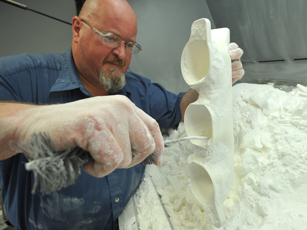
Decaking is currently done mostly by hand: human operators remove the residual powder manually with brushes, as shown in Figure 1, top. Recent 3D-printing technologies, such as HP MJF, enable printing hundreds, or even thousands, of parts in a single batch, making manual decaking a major bottleneck in 3D-printing-based mass manufacturing processes. There are some automated approaches to decaking, using for instance tumblers [5], but such approaches are unpractical if the powder is moderately sticky or if the parts are fragile.
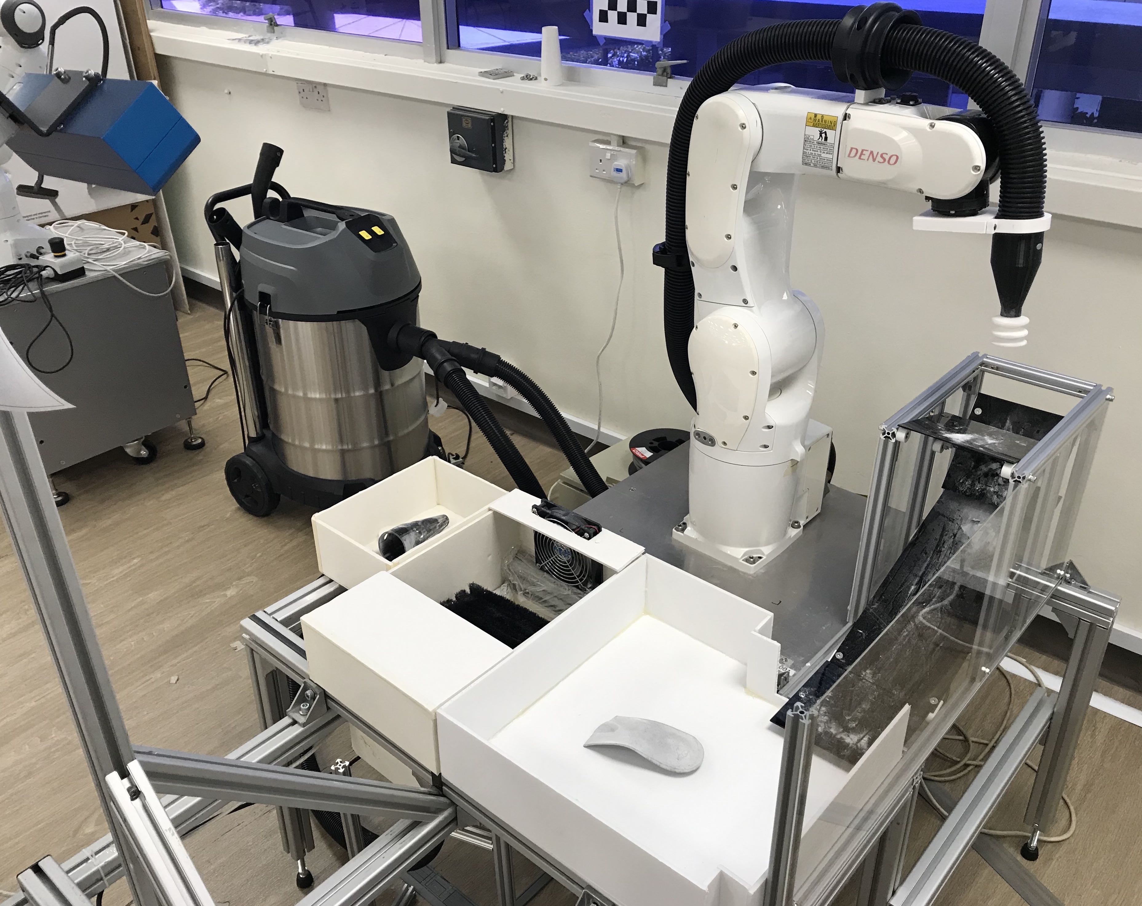
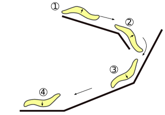
Here, we introduce, for the first time to our knowledge, a robotic system for automated decaking of 3D-printed parts, see Figure 1, bottom. Specifically, our system performs the following steps:
-
1.
Pick a caked part from the origin container with a suction cup;
-
2.
Clean the underside of the caked part by rubbing it on a brush;
-
3.
Flip the caked part;
-
4.
Clean the other side of the caked part;
-
5.
Place the cleaned part into the destination container.
Note that those steps are very general and can be applied to other 3D-printing processes and to most parts that are nearly flat.
Step 1 is essentially a bin-picking task, which has recently drawn significant attention from the community. However, the task at hand presents unique difficulties: (i) the caked parts contain unpredictable amount of residual powder, overlap each other, and are mostly white-colored (the color of the powder), making part detection and localization particularly challenging; (ii) the residual powder and the parts have different physical properties, making caked part manipulation, especially by a position-controlled industrial robot 111Most robots currently used in the industry are position-controlled, that is, they achieve highly accurate control in position and velocity, at the expense of poor, or no, control in force and torque. Yet, force or compliant control is crucial for contact tasks, such as part manipulation and decaking. A number of compliant robots have been developed in recent years but, compared to existing industrial robots, they are still significantly more expensive, less robust and more difficult to maintain., difficult. We address these challenges by leveraging respectively (i) recent advances in Deep Learning for 2D/3D vision; and (ii) smart mechanical design and force control.
Steps 2, 3 and 4 are specific to the decaking problem at hand. A particular challenge is the control of the contacts between the industrial robot, the parts, and the brushing system. We address this challenge by emphasizing smart mechanical design whenever possible (cleaning station, flipping station), and by using force control [6] to perform compliant actions when necessary. Our pipeline can be applied to all parts with nearly flat shapes, such as shoe insoles222The authors have been granted permission by Footwork Podiatry Laboratory to use their shoe insole design and images in this paper., which, to date, are popular in 3D-printing-based mass manufacturing processes.
The remainder of the paper is organized as follows. In Section II, we review related work in robotic cleaning, bin-picking, 3D perception, and force control. In Section III, we present our hardware system design. In Section IV, we describe our software stack. In Section V, we evaluate the system performance in number of actual decaking experiments, and demonstrate the feasibility of automated decaking. Finally, in Section VI, we conclude and sketch some directions for future research.
II Related work
Recent years have seen a growing interest in robotic surface/part cleaning. Advances in perception, control, planning and learning have been applied to the problem [7, 8, 9, 10]. Most research used robot manipulators to clean particles, powder or erase marker ink [7, 9, 11, 10], some considered mobile robots to vacuum dust, or objects lying on the floor, such as papers and clips [12, 13]. In fact, factors like variation in type of dust, shape of object, material, and environmental constraints require different approaches and techniques to tackle the problem. In this work, we are interested in the problem of cleaning 3D-printed parts which are randomly placed in a bin, and each part is covered by an unknown amount of residual or loose powder. Hence, we confine our review of prior work as follows:
As mentioned previously, the first step of our task is essentially a bin-picking task, which is one of the classical problems in robotics and have been investigated by many research groups, e.g. [14, 15, 16]. In these works, simplified conditions are often exploited, e.g. parts with simple geometric primitives, parts with holes to ease grasping action, parts with discriminative features.
Since the Amazon Picking Challenge 2015, a variety of approaches to a more general bin-picking problem had been proposed [17, 18, 19]. In [20], authors discussed their observations and lessons drawn from a survey conducted among participating teams in the challenge. Based on these lessons, we identified 3D perception, which recognizes objects and determining their 3D poses in a working space, as a key component to build a robust bin-picking system. Historically, most approaches to conduct instance object recognition are based on local descriptors around points of interest in images [21]. While these features are invariant to rotation, scale, and partial occlusions, they are not very robust to illumination changes or partial deformations of the object. Furthermore, since they depend on interest points and local features, they only work well for objects with texture. Recent advances in machine learning using convolutional neural networks (CNNs) have rapidly improved object detection and segmentation results [22, 23, 24, 25]. Our detection module is based on a Mask R-CNN model, which was originally open-sourced by Matterport Inc., and implemented in TensorFlow and Keras [23]. The Mask R-CNN model is an extension of the Faster R-CNN [22] model that achieved rapid object classification and bounding-box regression. Mask R-CNN adopts its two-stage procedure from Faster R-CNN. The first stage, called Regional Proposal Network (RPN), proposes candidate regions in which there might be an object in the input image. The second stage, in parallel, performs classification, refines the bounding-box and generates a segmentation mask of the object on each proposal region. Both stages are connected to a backbone structure.
Another important conclusion is that system integration and development are fundamental challenges to build task-specific, robust integrated systems. It is desirable to study integrated solutions which include all component technologies, such as 3D object pose estimation, control, motion planning, grasping, etc. Besides, it is also highlighted that good mechanical designs can sidestep challenging problems in control, motion planning and object manipulation. In line with this idea, our approach combines 3D perception using Deep Learning, smart mechanical design, motion planning, and force control for industrial robots, to develop a system that automatically decakes parts in a fast and efficient way.
In addition, another challenging problem that is unique to our decaking task is force control. To achieve compliant motion control, we take a position-controlled manipulator as a baseline system and make necessary modifications by following the pipeline in [26, 27] (thanks to its robustness). This enables safe and sufficient cleaning operations without the risk of damaging the parts. For more specific surveys on force control, interested readers can refer to [28, 29].
III Hardware system overview
We design our system while keeping in mind a scalable solution that could eventually tackle the problem of post-processing 3D-printed parts in a real scenario, at an advantageous cost. The robotic platform used in this work is, therefore, characterized by cost-efficient, off-the-shelf components combined with a classical position-control industrial manipulator. In particular, the main components of our platform are
-
•
1 Denso VS060: Six-axis industrial manipulator;
-
•
1 ATI Gamma Force-Torque (F/T) sensor;
-
•
1 Ensenso 3D camera N35-802-16-BL;
-
•
1 suction system powered by a Karcher NT 70/2 vacuum machine;
-
•
1 cleaning station;
-
•
1 flipping station.
All control and computations are done on a computer with an Intel Xeon E5-2630v3, 64 GB RAM.
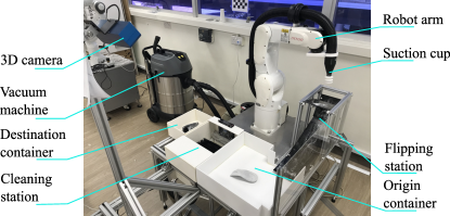
III-A Suction system
For grasping the parts, we decided to used a suction cup. This choice was motivated by the versatility and performance of suction-based system for bin-picking [20], and by fact that most recovered powders are recyclable. Our suction system is designed to generate both high vacuum and high air flow rate. This is to provide sufficient force to lift parts and to maintain a firm hold of parts during brushing. Air flow is guided from a suction cup on the tip of the end effector through a flexible hose into the vacuum machine. The vacuum itself is generated by a 2400W vacuum cleaner. For binary on/off control, we customize a 12V control output from the DENSO RC8 controller.
III-B Camera
Robust perception is a one of the key components of the system. We manually optimized the selection of camera and camera location to maximize the view angles; avoid occlusions from robot arm, end-effector and cleaning, picking, dropping stations; avoid collisions with objects and environment; and safety of the device.
For the sake of robustness, our system employs Ensenso 3D camera N35-802-16-BL and combines the use of both 2D grayscale image and depth information.
III-C Cleaning station
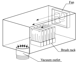
To clean the parts, a brush rack is installed at the bottom of the cleaning station. We also integrate a dust management system to collect excess powder removed during brushing. Throughout the cleaning process, a blowing fan is automatically activated to direct the powder stream frontward into the vacuum suction hose, see Figure 3.
III-D Flipping station
To change the part orientation, we implement a passive flipping station (i.e. no actuator is required to perform flipping). As illustrated in Figure 4, the part is dropped from the top of the station and moves along the guiding sliders. Upon reaching the bottom of the slider, the part is flipped and is ready to be picked up by the robot.
This design is simple but works well with relatively flat parts such as shoe insoles, flat boxes, etc. The next improvement of the station will accommodate general part geometry and provide more reorientation options.
IV Software system overview
Our software system is composed of a state machine and a series of modules. The communcation between different hardware and software components is based on the Robot Operating System (ROS) [30].
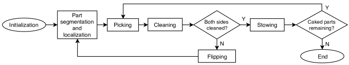
IV-A State machine
The state machine is responsible for selecting the appropriate module to execute at each point in time, see Figure 5. The solid arrows show the direction to next states depending on the result of current states. The state machine has access to all essential information of the system, including types, poses, geometries and cleanliness, etc. of all objects detected in the scene. Each module can query this information to realize its behavior. As a result, this design is general and can be adapted to many more types of 3D-printed parts. For example, the system can choose and execute a suitable cleaning strategy based on the type of part, its pose, and its prioritized list of actions; and decide whether to reattempt with a different strategy or skip that part based on the outcome. In our implementation, the modules were fine-tuned for each type of object based on previous experiments to obtain a high success rate. It is desirable to have a systematic approach to optimize the algorithm which decides the best cleaning strategy to use for each type of part (see Section V-C).
The state machine is also responsible for selecting the most feasible part to be decaked next. Since the parts are often cluttered or stacked, we generate the cleaning sequence by prioritizing parts with large top surfaces and are on top of the clutter. This is to perform suction easier and to de-stack parts in cluttered configurations.
IV-B Perception
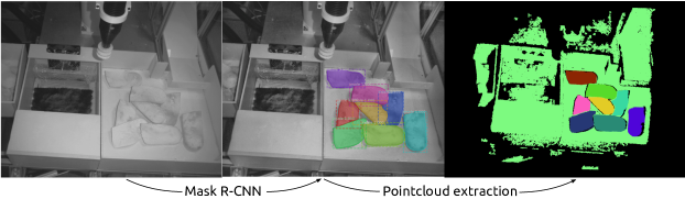
The perception task is to identify and localize visible objects in the working space. However, this is a challenging problem, due to heavy occlusions (i.e. self-occlusion and occlusion by powder) and the poor contrast between the freshly printed objects and their background. Our approach is to separate the perception into two stages: object detection, segmentation and 3D pose estimation. At the first stage, we utilize a state-of-the-art deep-learning network to perform instance detection and segmentation. The second stage extracts the 3D points of each object using the segmentation mask and estimate the object pose. This pipeline allow us to exploit the strength of deep-learning in processing 2D images and depth information in estimating object pose. We believe such combination of depth and RGB to be essential for a robust perception solution.
First, a deep neural network based on Mask R-CNN classifies the objects in the RGB image and performs instance segmentation, which provides pixel-wise object classification. The developers had provided a Mask R-CNN model that was pre-trained on large image classification datasets (Microsoft COCO dataset [31]). Hence, we applied transfer learning on the pre-trained model to save training time, by training the network to be able to classify a new object class. In our experiment, this network requires from 75-100 labelled images of real occurrences of typical 3D-printed parts. The result was at very high detection rate of all parts presenting in the bin, as shown in Figure 6. On average, our network has a recall of 0.967 and a precision of 0.975.
Second, pose estimation of the parts is done by estimating the bounding boxes and computing the centroids of the segmented pointclouds. The pointcloud of each object is refined (i.e. statistical outlier removal, normal smoothing, etc.) and used to verify if the object can be picked by suction (i.e. exposed surfaces must be larger than suction cup area). The 3D information of the bin is also used later during the motion planning for collision avoidance. We included heuristics to increase the robustness of the estimations by specifying physical constraints inside the bin e.g. parts must lie within the bin’s walls and cannot be floating within the bin.
We also note that the Ensenso camera cannot capture both 2D and 3D images simultaneously as the high-intensity IR light tends to blind the 2D camera. This module is, therefore, also in charge of turning on and off the high-intensity IR strobe to prevent it from affecting 2D images.
IV-C Motion primitives
Some modules, such as “Picking” and “Cleaning”, are themselves composed of a series of motion primitives.
Picking (suction-down) motion primitives
These primitives are useful for picking parts with exposed nearly flat surfaces. We limit our implementation to top-down directions. The process is as follows:
-
1.
The robot moves the suction cup above the centroid of the part and lowers the cup. Compliant force control is enabled and tells the robot when to stop the moving-down motion.
-
2.
Check whether the height at which the suction cup was stopped matches the expected height (from the point cloud with some tolerances).
-
3.
The suction cup lifts, and the system constantly checks the force torque sensor to determine whether there is any collision (which often results large drag forces).
Using suction is typically superior for parts with nearly flat and wide surfaces. However, even when the suction cup could not form a perfect seal with porous parts, high air flow often maintains sufficient force on the part to lift it. Moreover, the suction cup is versatile and can be replaced to fit many types of object.
Cleaning motion primitives
These primitives remove residual powder and debris from the printed parts. Our current implementation of these primitives is limited to parts that are nearly flat (e.g. shoe insoles).
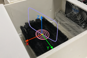
First, the robot positions the part above the brush rack in the cleaning station. Then, the compliant force control mode is enabled to move the robot until contact with the brushes. Next, the cleaning trajectories are performed. To maintain constant contact between the brushes and the part, we apply a hybrid position/force control scheme: force is regulated in the direction normal to the brushes’ surfaces, while position is regulated in the tangential directions. The force thresholds are determined through a number of trial-error experiments. The cleaning trajectories are planned following two patterns: spiral and rectircle (see Figure 7). While the spiral motion is well-suited for cleanning nearly flat surfaces, the rectircle motion aids with removing powder in concave areas.
IV-D Motion planning and control
V System performance and discussion
V-A Experimental setup
Parts considered in the experiments were 3D-printed shoe insoles. At the current stage of development, we assumed all parts to be unpacked from printer powderbed and placed randomly in container bin. The task of the system was to remove powder from the parts, which naturally consisted of several key steps as follows:
-
1.
Initial localization of parts in container bin,
-
2.
Picking a part out of the container bin,
-
3.
Removing residual powder from the underside of the part,
-
4.
Flipping the part,
-
5.
Re-localizing parts in the container bin and in the flipping collection area,
-
6.
Picking flipped part,
-
7.
Removing residual powder from the other side of the part,
-
8.
Placing the part into the collection bin and continuing with any remaining parts (Step 2-8).
V-B Performance
The sytem performed the cleaning task on 10 freshly 3D-printed shoe insoles. Two aspects of the proposed system were experimentally investigated. First, we evaluated the cleaning quality by weighing the parts before and after cleaning. Second, we reported the actual running time of the proposed system in a realistic setting. As the baseline for comparison, we also considered the same task performed by skilled human operators. The results of this experiment are summarized in Table I.
As expected, the performance of the system yielded a promising result as a first prototype. Two test runs were conducted and successfully executed by the proposed system. We noted that a perfectly cleaned printed shoe insoles weighed g on average. The proposed system could remove powder from a dirty part on an average of s and parts weighed g on average after cleaning, which meant excess powder has been removed from the parts. In comparison, a skilled human operator could clean of excess powder (parts weighed g after cleaning in s on average). Although our system performance regarding the cleaning quality was 1.7 times less than that of a human operator, this was a potential outcome as our robot system is supposed to work significantly longer. This however raised questions how task efficiency could be further improved.
V-C Discussion
We observed that our system performed actual brushing actions in only of the execution time. In comparison, human spent more than execution time on brushing. This was attributed to human superior skills in performing sensing and dexterous manipulations. However, when we limited brushing time to 20s, cleaning quality was reduced as parts weighed g on average after cleaning (removed excess powder). This suggested that one could improve cleaning quality by prolonging the brushing duration and upgrading the cleaning station (e.g. spinning brushes to speed up cleaning action; compliant brushes to clean concave areas, etc.).
We also noted that humans provided more consistent results of cleaned parts (i.e. parts cleaned by human operators had weight variation much smaller than that of parts cleaned by our system). This was due to the fact that human operators actively adjusted their cleaning motions based on vision feedback. Hence, incorporating a cleanliness evaluation module into the current system would improve the cleaning quality performance. For this purpose, another 3D camera could be used to observe the object after each cleaning section. The module would retrieve a list of all dirty locations on object surfaces. This information would allow the system to plan better cleaning motions and could also be utilized to validate cleaning results.
Moreover, though this experiment featured a batch of nearly the same 3D-printed shoe insoles, our ultimate goal would be to extend this robotic system to a various types of 3D-printed parts. For example, in many cases, a batch of 3D-printed parts may contain a number of different parts. The cleaning routines, hence, would have to be altered to cater to the different geometries of each parts. To achieve that, the state machine can be encoded with specific cleaning instructions for each type of part. Much in the same way human operators change cleaning routines for different parts, our robotic system may recognize different parts, look up a prior defined handling instructions, perform the cleanliness evaluation and execute accordingly.
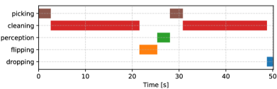
To investigate the computational cost of our approach, Figure 8 also provides information on the average times of each action used when performing the task. We noted that our robot ran at max speed and all motions were planned online. Hence, the sytem performance could be further enhanced by optimizing these modules (e.g. off-line planning for tight-space motions, working space optimization, etc.). Moreover, our perception module was running on a CPU, implementations of better computing hardware would thus improve the perception speed.
Furthermore, we are also working forward improving our end-effector design. The current system is only capable of performing suction-down motion primitives. Though it can accommodate for a very large tilting angle, our system does not have enough maneuverability to perform side picking. A possible approach would be to design a more generic suction gripper to perform the task. Another solution would be to add another assisting motion primitive, which is Toppling whose goal is not to pick, but to change the configuration of an object that cannot be picked by the other primitives. It is called in particular when the exposed face of an object is too narrow. In this scenario it may be possible to topple the object into a new configuration that will allow the object to be picked by suction. Finally, air flow can be measured by using a pitot tube inside the suction cup/hose. This is used to detect whether a part was successfully grasped or lost during arm motions.
| Avg per part | Our system | Human (no time-limit) | Human (20s brushing) |
|---|---|---|---|
| Mass Before (g) | |||
| Mass After (g) | |||
| Cycle Time (s) | |||
| Brushing Time (s) | 20 | 40 | 20 |
VI Conclusion
In this paper, we have presented an automated robotic system for decaking 3D-printed parts. We have combined Deep Learning for 3D perception, smart mechanical design, motion planning and force control for industrial robots to develop a system that can perform decaking task in a fast and efficient manner. Through a series of experiments performed on parts printed by a HP Multi Jet Fusion printer, we demonstrated the feasibility of automatizing such tasks. The achievements of this first prototype are promising and lay the groundwork for multiple possible extensions: to other types of parts, to other powder-based 3D-printing processes (SLM, SLS, binder jet, etc.) In future work, we will focus on validating the current system further and expanding it to more general scenarios e.g. incorporating a cleanliness evaluation module, optimizing task efficiency and adapting the system to work on more general parts.
Acknowledgment
This research was conducted in collaboration with HP Inc. and partially supported by the Singapore Government through the Industry Alignment Fund -Industry Collaboration Projects Grant.
References
- [1] E. M. Sachs, J. S. Haggerty, M. J. Cima, and P. A. Williams, “Three-dimensional printing techniques,” Apr. 20 1993, US Patent 5,204,055.
- [2] Y. Bai and C. B. Williams, “An exploration of binder jetting of copper,” Rapid Prototyping Journal, vol. 21, no. 2, pp. 177–185, 2015.
- [3] E. O. Olakanmi, R. Cochrane, and K. Dalgarno, “A review on selective laser sintering/melting (SLS/SLM) of aluminium alloy powders: Processing, microstructure, and properties,” Progress in Materials Science, vol. 74, pp. 401–477, 2015.
- [4] hp.com. (2019) HP multi jet fusion technology. [Online]. Available: https://www8.hp.com/sg/en/printers/3d-printers/products/multi-jet-technology.html
- [5] A. Ju, A. Fitzhugh, J. Jun, and M. Baker, “Improving aesthetics through post-processing for 3D printed parts,” Electronic Imaging, vol. 2019, no. 6, pp. 480–1, 2019.
- [6] G. Zeng and A. Hemami, “An overview of robot force control,” Robotica, vol. 15, no. 5, pp. 473–482, 1997.
- [7] F. Sato, T. Nishii, J. Takahashi, Y. Yoshida, M. Mitsuhashi, and D. Nenchev, “Experimental evaluation of a trajectory/force tracking controller for a humanoid robot cleaning a vertical surface,” in 2011 IEEE/RSJ international conference on intelligent robots and systems, 2011, pp. 3179–3184.
- [8] F. Nagata, T. Hase, Z. Haga, M. Omoto, and K. Watanabe, “CAD/CAM-based position/force controller for a mold polishing robot,” Mechatronics, vol. 17, no. 4-5, pp. 207–216, 2007.
- [9] J. Hess, G. D. Tipaldi, and W. Burgard, “Null space optimization for effective coverage of 3d surfaces using redundant manipulators,” in IEEE/RSJ International Conference on Intelligent Robots and Systems, 2012, pp. 1923–1928.
- [10] C. Eppner, J. Sturm, M. Bennewitz, C. Stachniss, and W. Burgard, “Imitation learning with generalized task descriptions,” in International Conference on Robotics and Automation. IEEE, 2009, pp. 3968–3974.
- [11] J. Hess, M. Beinhofer, and W. Burgard, “A probabilistic approach to high-confidence cleaning guarantees for low-cost cleaning robots,” in International conference on robotics and automation (ICRA). IEEE, 2014, pp. 5600–5605.
- [12] G. Lawitzky, “A navigation system for cleaning robots,” Autonomous Robots, vol. 9, no. 3, pp. 255–260, 2000.
- [13] J. L. Jones, “Robots at the tipping point: the road to irobot roomba,” IEEE Robotics & Automation Magazine, vol. 13, no. 1, pp. 76–78, 2006.
- [14] B. Drost, M. Ulrich, N. Navab, and S. Ilic, “Model globally, match locally: Efficient and robust 3d object recognition,” in Computer society conference on computer vision and pattern recognition. IEEE, 2010, pp. 998–1005.
- [15] D. Buchholz, D. Kubus, I. Weidauer, A. Scholz, and F. M. Wahl, “Combining visual and inertial features for efficient grasping and bin-picking,” in International Conference on Robotics and Automation (ICRA). IEEE, 2014, pp. 875–882.
- [16] A. Pretto, S. Tonello, and E. Menegatti, “Flexible 3D localization of planar objects for industrial bin-picking with monocamera vision system,” in International Conference on Automation Science and Engineering (CASE). IEEE, 2013, pp. 168–175.
- [17] C. Eppner, S. Höfer, R. Jonschkowski, R. Martín-Martín, A. Sieverling, V. Wall, and O. Brock, “Lessons from the amazon picking challenge: Four aspects of building robotic systems.” in Robotics: Science and Systems, 2016.
- [18] C. Hernandez, M. Bharatheesha et al., “Team delft’s robot winner of the amazon picking challenge 2016,” in Robot World Cup. Springer, 2016, pp. 613–624.
- [19] K.-T. Yu, N. Fazeli, N. Chavan-Dafle, O. Taylor, E. Donlon, G. D. Lankenau, and A. Rodriguez, “A summary of team MIT’s approach to the amazon picking challenge 2015,” arXiv preprint arXiv:1604.03639, 2016.
- [20] N. Correll, K. E. Bekris, D. Berenson, O. Brock, A. Causo, K. Hauser, K. Okada, A. Rodriguez, J. M. Romano, and P. R. Wurman, “Lessons from the amazon picking challenge,” arXiv preprint arXiv:1601.05484, vol. 3, 2016.
- [21] D. Lowe, “Object recognition from local scale-invariant features.” in International Conference on Computer Vision, vol. 99, no. 2. IEEE, 1999, pp. 1150–1157.
- [22] S. Ren, K. He, R. Girshick, and J. Sun, “Faster R-CNN: Towards real-time object detection with region proposal networks,” in Advances in neural information processing systems, 2015, pp. 91–99.
- [23] K. He, G. Gkioxari, P. Dollár, and R. Girshick, “Mask R-CNN,” in Proceedings of the IEEE international conference on computer vision, 2017, pp. 2961–2969.
- [24] W. Liu, D. Anguelov, D. Erhan, C. Szegedy, S. Reed, C.-Y. Fu, and A. C. Berg, “SSD: Single shot multibox detector,” in European conference on computer vision. Springer, 2016, pp. 21–37.
- [25] J. Redmon and A. Farhadi, “YOLO9000: better, faster, stronger,” in Proceedings of the IEEE conference on computer vision and pattern recognition, 2017, pp. 7263–7271.
- [26] F. Suárez-Ruiz, X. Zhou, and Q.-C. Pham, “Can robots assemble an IKEA chair?” Science Robotics, vol. 3, no. 17, p. eaat6385, 2018.
- [27] C. Ott, R. Mukherjee, and Y. Nakamura, “Unified impedance and admittance control,” in International Conference on Robotics and Automation. IEEE, 2010, pp. 554–561.
- [28] T. Lefebvre, J. Xiao, H. Bruyninckx, and G. De Gersem, “Active compliant motion: a survey,” Advanced Robotics, vol. 19, no. 5, pp. 479–499, 2005.
- [29] A. Calanca, R. Muradore, and P. Fiorini, “A review of algorithms for compliant control of stiff and fixed-compliance robots,” IEEE/ASME Transactions on Mechatronics, vol. 21, no. 2, pp. 613–624, 2015.
- [30] M. Quigley, K. Conley, B. Gerkey, J. Faust, T. Foote, J. Leibs, R. Wheeler, and A. Y. Ng, “ROS: an open-source robot operating system,” in ICRA workshop on open source software, vol. 3, no. 3.2. Kobe, Japan, 2009, p. 5.
- [31] T.-Y. Lin, M. Maire, S. Belongie, J. Hays, P. Perona, D. Ramanan, P. Dollár, and C. L. Zitnick, “Microsoft COCO: Common objects in context,” in European conference on computer vision. Springer, 2014, pp. 740–755.
- [32] J. J. Kuffner Jr and S. M. LaValle, “RRT-connect: an efficient approach to single-query path planning,” in International Conference on Robotics and Automation, vol. 2. IEEE, 2000.
- [33] R. Diankov, “Automated construction of robotic manipulation programs,” Ph.D. dissertation, Carnegie Mellon University, 2010.