Relativistic electron beam, Backward Raman scattering and soft X-ray laser
Abstract
A scheme for soft x-ray lasers is proposed. The backward Raman scattering between an intense visible-light laser and a relativistic electron beam results in soft x-ray light via the Doppler shift. One of the most intense soft x-ray light sources is contemplated.
pacs:
42.55.Vc, 42.65.Dr,42.65.Ky, 52.38.-r, 52.35.HrThere have been exploding interests in a high-intensity (high-power) x-ray light source, which would be critical in the atomic spectroscopy, the dynamical imaging of biological processes, the next-generation semi-conductor lithography and many others. While its impacts on the sciences and the practical applications are immense, the most advanced x-ray sources Son et al. (2012a); Colson (1985); Son and Moon (2012); Gallardo (1988); Son et al. (2012b); Carr et al. (2002); Williams (2002); Wabnitz et al. (2002); Emma et al. (2004) are not intense or efficient enough for mentioned applications.
One emerging way to generate intense x-ray is to utilize the scattering between an intense laser and a relativistic electron beam. This methods becomes very attractive as the table-top electron beam accelerator (intense laser) is readily available. In this paper, the author proposes a soft x-ray light source by further amplifying the interaction between the laser and the electron beam via the backward Raman scattering (BRS). There have been some efforts to generate the x-ray via the BRS Esarey and Sprangle (1992); Sprangle and Drobot (1979); Drake et al. (1974); McDermott et al. (1978), where the second or third harmonic interaction McDermott et al. (1978); Esarey and Sprangle (1992); Sprangle and Drobot (1979) or the milimeter wave based the conventional magnets McDermott et al. (1978) is utilized to generate XUV light. However, its efficency (intensity and power) was low and the wave-length of the resulted XUV light was comparable to 100 nm, that is too large for many important applications. On the other hand, what has never been attempted is to utilize the relativistic Doppler effect directly or the first harmonic of the BRS. Noting that the great advances in intense visible-light lasers Strickland and Mourou (1985); Perry and Mourou (1994); Brabec and Krausz (2000) and dense relativistic electron beams Mangles et al. (2004); Tatarakis et al. (2003) have been made recently, the possibility to directly use the first harmonic and the relativistic Doppler’s effect is proposed in this paper.
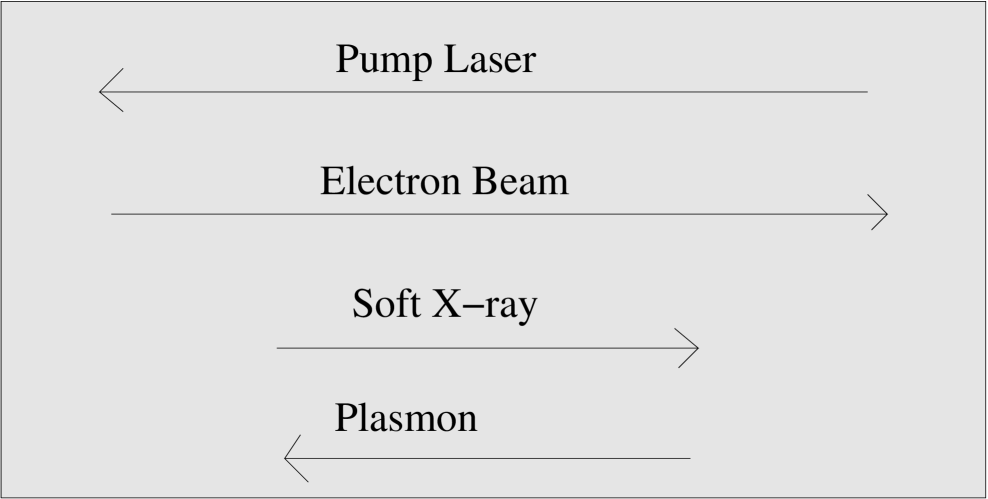
The main idea is as follows. First, a dense electron beam and an intense visible-light laser (pump laser) propagate in the opposite direction. Second, the ponderomotive interaction between the laser and a weak or background x-ray light (seed pulse) excites a Langmuir wave. Third, the backward Raman scattering between the Langmuir wave and the laser amplifies the x-ray light (seed pulse) in the electron beam direction and up-shfited in frequency via the relativistic Doppler’s effect. See Fig. (1) for the direction of the visible-light laser, the soft x-ray light (seed pulse) and the Langmuir wave. In this paper, the physics of the above processes will be analyzied and the prospect as a x-ray light source will be presented. The analysis here suggests the most efficient and intense x-ray light source with the achieved x-ray wave length of 10 nm rather than 100 nm, which is ideal for many important applications.
To begin, let me consider an intense visible-laser with frequency (wave vector ) and a counter-propagating dense electron beam with the electron density and the relativistic factor , where is the velocity of the electron beam. In the co-moving frame with the electron beam, the electron density decreases to due to the length dilation. The 1-D BRS three-wave interaction in the co-moving frame between the pump, the seed and a Langmuir wave is described by McKinstrie and Simon (1986):
| (1) | |||
where is the ratio of the electron quiver velocity of the pump pulse () and the seed pulse () relative to the velocity of the light , is the electric field of the E&M pulse, is the Langmuir wave amplitude, () is the rate of the inverse bremsstrahlung of the pump (seed), is the plasmon decay rate, for , , () is the frequency of the pump (seed) pulse and is the plasmon wave frequency.
In the co-moving frame, the wave vector satisfies the usual dispersion relationship, , where () is the wave frequency (vector) and is the plasmon frequency. Denote the wave vector (the corresponding wave frequency) of the pump laser (the seed pulse or soft x-ray) in the co-moving frame as , , and , and the laboratory-frame counterparts as , , and . The Lorentz transform prescribes the following relationship:
| (2) | |||||
| (3) | |||||
| (4) | |||||
| (5) |
Using Eqs. (2), (3), (4) and (5), the pump laser (seed pulse or soft x-ray) can be transformed from the co-moving frame to the laboratory frame or vice versa.
The energy and momentum conservation of Eq. (1) lead to
| (6) |
where is the plasmon wave vector. For a given pump frequency , () is obtained from Eq. (2), () is from Eq. (6) and, finally, () is from Eqs. (4) and (5). In the limit when , or
| (7) |
using and . The Eq. 7 describes the frequency up-shift of the pump pulse into the soft x-ray by the relativistic Doppler’s effect.
The growth rate of the BRS is obtained from the linear analysis of Eq. (1). When and , the linearization of Eq. (1), in the form with or , leads to
| (8) |
If and , the growth rate, the imaginary part of the solution of Eq. (8), is . In the limiting case when , it can be simplified to
| (9) |
where , , , and thus . If we define the electron beam length as and the laser length as , the beam length increases to and the laser length decreases to in the co-moving frame so that the interaction time between the beam and laser is . The gain-per-length is then
| (10) |
Considering an electron beam with the electron density of and ND:YAG laser with the wave length of 1 , and from Eq. (9) if the laser intensity is . If , the amplified wave has the wave length of 2.5 nm from Eq. (7) and the gain-per-length is, from Eq. (10), when and when . For the same condition but with the laser intensity of , and the gain-per-length is when and when ; the gain-per-length is higher than any other conventional soft x-ray lasers by a few factors Afana’ev and Kalynov (1989); Nilsen (1997); Dunn et al. (2000)
| Type | ||||||||
|---|---|---|---|---|---|---|---|---|
| N | 2.5 | 1 | 10 | 0.02 | 5.18 | 17 | 0.08 | 64 |
| N | 2.5 | 100 | 10 | 0.6 | 164 | 547 | 2.7 | 64 |
| N | 2.5 | 0.01 | 10 | 0.002 | 0.5 | 1.7 | 0.009 | 64 |
| N | 10 | 1 | 5 | 0.02 | 4.3 | 7.2 | 0.14 | 4 |
| N | 10 | 5 | 0.6 | 137 | 230 | 4.6 | 4 | |
| N | 27.8 | 1 | 3 | 0.02 | 3.8 | 3.8 | 0.21 | 0.51 |
| N | 27.8 | 0.01 | 3 | 0.002 | 0.38 | 0.38 | 0.02 | 0.51 |
| N | 27.8 | 3 | 0.6 | 121 | 121 | 6.7 | 0.51 | |
| C | 2.5 | 1 | 31.6 | 0.2 | 21.8 | 30.5 | 0.1 | 6.4 |
| C | 2.5 | 30 | 31.6 | 1.1 | 119.7 | 1262 | 0.6 | 6.4 |
| C | 10 | 1 | 15.8 | 0.2 | 18.3 | 96.9 | 0.2 | 0.4 |
| C | 10 | 0.001 | 15.8 | 0.006 | 0.5 | 3 | 0.006 | 0.4 |
| C | 25 | 1 | 10 | 0.2 | 16.4 | 54.7 | 0.27 | 0.064 |
| C | 25 | 0.01 | 10 | 0.02 | 1.64 | 5.5 | 0.027 | 0.064 |
The estimation of the conversion efficiency from the pump laser energy to the seed pulse follows. Define as the conversion efficiency in the co-moving frame. Let be the total energy of the pump laser in the laboratory frame. Then, the pump energy in the co-moving frame is via the Doppler effect, the energy converted to the seed pulse is , and the total energy of the seed pulse in the laboratory frame is , resulting the effective conversion efficiency as
| (11) |
Given the fact that can be comparable to the unit in an optimistically envisioned scenario Malkin and Fisch (2007a); Malkin et al. (2000); Son et al. (2010a); Russell et al. (1999); Sakharov and Kirsanov (1994); Clark and Fisch (2003), it is possible that or the conversion efficiency can be larger than 100 percents. This extraordinary high conversion efficiency can be explained as follows. In the co-moving frame, the laser will be scattered into a seed photon and a plasmon, during which the plasmon (the seed photon) acquires the momentum (). In the laboratory frame, the momentum (energy) of the plasmon is much larger than that of the pump photon due to the Doppler effect and the kinetic energy loss of the electron beam, when the plasmon is excited, is even higher than the pump photon energy. In other words, the seed pulse gets most of its energy not from the pump pulse but from the electron beam (by the ratio of ). The relativistic electron beam can support the wave with negative energy in the laboratory frame.
In the high conversion efficiency as discussed, the BRS might be already in the non-linear saturated regime, in which is as intense as . The wave breaking limit might be simply put as . From Eq. (1),
| (12) |
where I assume that . Using Eq. (1) and Eq. (12), the growth rate of the seed pulse is . Assuming ,
| (13) |
which prescribes the upper-bound of the growth rate in the non-linear saturated regime.
In order for the current scheme to be plausible, there are two necessary conditions to be met for the laser beam intensity and electron beam density. One necessary condition would be that for a sufficient amplification or
| (14) |
which can be satisfied by currently available intense visible-light lasers Strickland and Mourou (1985); Perry and Mourou (1994); Brabec and Krausz (2000). Another necessary condition for the collective BRS is , as only the Langmuir wave with is a collective wave. In the limiting case when , it is simplified to
| (15) |
where and are assumed. In addition, the wave vector of the Langmuir wave should be larger than the Debye length
| (16) |
where . The condition given by Eqs. (15) and (16) is the minimum lower bound of the electron beam density for the BRS compression and can be met easily in the currently available dense electron beams Mangles et al. (2004); Tatarakis et al. (2003) while the electron temperature low enough to satisfy Eq. (16).

To be more specific, the gain analysis for various electron beams and lasers are provided in the Table (1). Those results suggest that the scheme is plausible for a wide range of frequencies, the requirement of the laser intensity is moderate compared to other laser based schemes Son and Moon (2012); Son et al. (2012a, b); Gallardo (1988); McDermott et al. (1978); Esarey and Sprangle (1992); Sprangle and Drobot (1979), the gain-per-length can be as high as and the optimal relativistic factor is . In Table (1), for the cases of the CO2 laser with the and , the temperature constraint given by Eq. (16), assuming the electron density is , might be too stringent . Generally, the generation of the short wave-length x-ray by the CO2 laser could put the density requirement higher than given by for reasonable electron temperature. If for the ND:YAG laser as in the Table (1), the electron quiver velocity becomes marginally relativistic and the full relativistic treatment is necessary McDermott et al. (1978), which is ignored in this paper.
The desired intensity for the coherent dynamical imaging Muchmore et al. (2012); Whitesides et al. (2001) is . In Fig. (2), the 1-D simulation of Eq. (1) shows that the desired intensity for the coherent dynamical imaging can be reached without any additional focusing. In Fig. (2), the pump (x-ray) propagetes from the right (left) to the left (right) and the x-ray pulse extracts energy from the pump pulse via the BRS, resuting the final energy of the x-ray pulse larger than its initial energy by a factor of . In this example, the pump laser has the intensity of () in the co-moving frame (the laboratory frame); the intensity of the pump laser (x-ray pulse) is lower (higher) by 36 times in the laboratory frame than in the co-moving frame due to the Doppler’s effect. For the simulation shown in Fig. (2), the final peak intensity of the x-ray pulse in the co-moving frame is larger by 10 times than the intensity of the pump laser; the attained peak intensity of the x-ray pulse is in the laboratory frame.
In summary, the scheme achieves the soft x-ray light laser with the highest gain-per-length as shown in Table 1. The gain-per-length can be as high as to , which is order magnitude higher than the current technologies Afana’ev and Kalynov (1989); Nilsen (1997); Dunn et al. (2000), and the peak x-ray intensity can be as high as or even higher than the pump laser. The desired peak intensity of the coherent x-ray is for the coherent dynamical imaging Muchmore et al. (2012); Whitesides et al. (2001) can be reached under the proposed scheme without any additional focusings.
The comparison between ND:YAG laser and the CO2 laser is made in the Table 1; the ND:YAG laser is more advantageous in one-time intense x-ray burst but the CO2 laser would be better for the industry applications that need the high conversion efficiency and high-repetition rate. As demonstrated in the Raman compression of the visible-light laser Malkin and Fisch (2007a); Malkin et al. (2000); Son et al. (2010a); Russell et al. (1999); Sakharov and Kirsanov (1994); Clark and Fisch (2003), the BRS is much stronger than the individual electron. As an illustration, considering the electron plasma with the density and the visible-light laser with the intensity of , the BRS is times larger than the conventional Thomson scattering. This strong BRS is the main motivating physics that the author tries to utilize in this paper.
The performance of the proposed scheme relies on the quality of the electron beam such as the uniformity and the time duration in which the beam maintains its quality. Electron beam can deteriorate in a very fast time scale due to the space charge effect and in order to mitigate this effect, it probably needs to propagate inside a plasma of comparable electron density. The inverse bremsstrahlung is another concern. For such a high beam density, the inverse bremsstrahlung rate could be as high as and higher for ultra-intense laser. If the pump laser is very intense, the heating by the inverse bremsstrahlung increases the electron temperature considerably in a few hundred Langmuir periods and the excitation of the appropriate Langmuir wave is no-longer feasible as the condition given in Eq. (16) is breached due to the heavy Landau damping. However, even if the performances are compromised due to the mentioned issues, the scheme proposed is important given the the possible highest gain strength (conversion efficiency).
References
- Son et al. (2012a) S. Son, S. J. Moon, and J. Y. Park, Optics Letters 37, 5172 (2012a).
- Colson (1985) W. B. Colson, Nucl. Inst. Meth. Phys. A 237, 1 (1985).
- Son and Moon (2012) S. Son and S. J. Moon, Phys. Plasmas 19, 063102 (2012).
- Gallardo (1988) J. C. Gallardo, IEEE J. Quantum. Elec. 24, 1557 (1988).
- Son et al. (2012b) S. Son, S. J. Moon, and J. Y. Park, Phys. Plasmas 19, 114503 (2012b).
- Carr et al. (2002) G. L. Carr, M. C. Martin, W. R. Mckinney, K. Jordan, G. R. Neil, and G. P. Williams, Nature 420, 153 (2002).
- Williams (2002) G. P. Williams, Review of Scientific Instruments 73, 1461 (2002).
- Wabnitz et al. (2002) H. Wabnitz, L. Bittner, A. R. B. de Castro, R. Dohrmann, P. Gurtler, T. Laarmann, W. Laasch, J. Schulz, A. Swiderski, K. von Haeften, et al., Nature 420, 482 (2002).
- Emma et al. (2004) P. Emma, K. Bane, M. Cornacchia, Z. Huang, H. Schlarb, G. Stupakov, and D. Walz, Phys. Rev. Lett 92, 074801 (2004).
- McDermott et al. (1978) D. B. McDermott, T. C. Marshall, S. P. Schlesinger, R. K. Parker, and V. L. Granatstein, Phys. Rev. Lett. 41, 1368 (1978).
- Esarey and Sprangle (1992) E. Esarey and P. Sprangle, Phys. Rev. A 45, 5872 (1992).
- Sprangle and Drobot (1979) P. Sprangle and A. T. Drobot, Journal of Applied Physics 50, 2652 (1979).
- Drake et al. (1974) J. F. Drake, P. K. Kaw, Y. C. Lee, G. Schmidt, C. S. Lis, and M. N. RosenBluth, Phys. Fluids 17, 778 (1974).
- Strickland and Mourou (1985) D. Strickland and G. Mourou, Phys. Fluids 55, 447 (1985).
- Perry and Mourou (1994) M. D. Perry and G. Mourou, Science 264, 917 (1994).
- Brabec and Krausz (2000) T. Brabec and F. Krausz, Rev. Mod. Phys. 72, 545 (2000).
- Mangles et al. (2004) S. P. D. Mangles, C. D. Murphy, Z. Najmudin, A. G. R. Thomas, J. L. Collier, A. E. Dangor, E. J. Divall, P. S. Foster, J. G. Gallacher, C. J. Hooker, et al., Nature 431, 535 (2004).
- Tatarakis et al. (2003) M. Tatarakis, F. N. Beg, E. L. Clark, A. E. Dangor, R. D. Edwards, R. G. Evans, T. J. Goldsack, K. W. D. Ledingham, P. A. Norreys, M. A. Sinclair, et al., Phys. Rev. Lett. 90, 175001 (2003).
- McKinstrie and Simon (1986) C. J. McKinstrie and A. Simon, Phys. Fluids 29, 1959 (1986).
- Afana’ev and Kalynov (1989) Y. Afana’ev and V. S. Y. K. Kalynov, Sov. J. Quantum Electron 19, 1506 (1989).
- Nilsen (1997) J. Nilsen, J. Opt. Soc. Am. B 14, 1511 (1997).
- Dunn et al. (2000) J. Dunn, Y. Li, A. L. Osterheld, J. Nelson, J. R. Hunter, and V. N. Shlyaptsev, Phys. Rev. Lett. 84, 4834 (2000).
- Malkin and Fisch (2007a) V. M. Malkin and N. J. Fisch, Phys. Rev. Lett. 99, 205001 (2007a).
- Malkin et al. (2000) V. M. Malkin, G. Shvets, and N. J. Fisch, Phys. Rev. Lett. 84, 1208 (2000).
- Son et al. (2010a) S. Son, S. Ku, and S. J. Moon, Phys. Plasmas 17, 114506 (2010a).
- Russell et al. (1999) D. A. Russell, D. F. DuBois, and H. A. Rose, Phys. Plasmas 6, 1294 (1999).
- Sakharov and Kirsanov (1994) A. S. Sakharov and V. I. Kirsanov, Phys. Rev. E 49, 3274 (1994).
- Clark and Fisch (2003) D. S. Clark and N. J. Fisch, Phys. Plasmas 10, 4837 (2003).
- Muchmore et al. (2012) S. W. Muchmore, M. Sattler, H. Liang, R. P. Meadows, J. E. Harlan, H. S. Yoon, D. Nettesheim, B. S. Chang, C. B. Thompson, S. L. Wong, et al., Nature 381, 335 (2012).
- Whitesides et al. (2001) G. W. Whitesides, E. Ostuni, S. Takayama, X.Jiang, and D. E. Ingber, Annual Review of Biomedical Engineering 3, 335 (2001).
- Son and Ku (2009) S. Son and S. Ku, Phys. Plasmas 17, 010703 (2009).
- Son and Moon (2011a) S. Son and S. J. Moon, Appl. Phys. Lett. 98, 081501 (2011a).
- Son et al. (2010b) S. Son, S. Ku, and S. J. Moon, Phys. Plasmas 17, 114506 (2010b).
- Malkin and Fisch (2007b) V. M. Malkin and N. J. Fisch, Phys. Rev. Lett. 99, 205001 (2007b).
- Son and Moon (2011b) S. Son and S. J. Moon, Phys. Plasmas 18, 084504 (2011b).
- Son et al. (2010c) S. Son, S. Ku, and S. J. Moon, Phys. Plasmas 17, 112709 (2010c).
- Tabak et al. (1994) M. Tabak, J. Hammer, M. E. Glinsky, W. L. Kruerand, S. C. Wilks, J. Woodworth, E. M. Campbell, M. J. Perry, and R. J. Mason, Physics of Plasmas 1, 1626 (1994).
- Son and Fisch (2005a) S. Son and N. J. Fisch, Phys. Rev. Lett. 95, 225002 (2005a).
- Son and Fisch (2004) S. Son and N. J. Fisch, Phys. Lett. A 329, 16 (2004).
- Son and Fisch (2006a) S. Son and N. J. Fisch, Phys. Lett. A 356, 65 (2006a).
- Son and Fisch (2006b) S. Son and N. J. Fisch, Phys. Lett. A 356, 72 (2006b).
- Son and Fisch (2005b) S. Son and N. J. Fisch, Phys. Lett. A 337, 397 (2005b).