Robotic Assembly across Multiple Contact Stiffnesses with
Robust
Force Controllers
Abstract
Active Force Control (AFC) is an important scheme for tackling high-precision robotic assembly. Classical force controllers are highly surface-dependent: the controller must be carefully tuned for each type of surface in contact, in order to avoid instabilities and to achieve a reasonable performance level. Here, we build upon the recently-developed Convex Controller Synthesis (CCS) to enable high-precision assembly across a wide range of surface stiffnesses without any surface-dependent tuning. Specifically, we demonstrate peg-in-hole assembly with 100 micron clearance, initial position uncertainties up to 2 cm, and for four types of peg and hole materials – rubber, plastic, wood, aluminum – whose stiffnesses range from 10 to 100 N/mm, using a single controller.
I Introduction
Active Force Control (AFC) is an important scheme for tackling high-precision robotic assembly, such as peg or shaft insertion into holes, memory module insertion onto motherboards, or gear assembly, see e.g. [1]. In AFC, contact force measurements obtained from a wrist-mounted force sensor are used in a feedback loop to guide the robot motion. A typical task in AFC is to maintain a desired level of normal contact force between the robot and a surface. Classical AFC suffers from the following fundamental problem: the controller must be carefully tuned for each type of surface in contact. A controller tuned for a soft surface might become unstable when making contact with a hard surface, while a controller tuned for a hard surface might be overly sluggish when the task involves soft surfaces [2]. Furthermore, the tuning of classical AFC controllers is time-consuming and requires considerable expertise. Because of those issues, high-precision automated assembly under large uncertainties (in the surface stiffnesses, in the initial positions of the parts) remains an outstanding industrial challenge.
In this paper, we build upon the recently-developed Convex Controller Synthesis (CCS) [2] to enable high-precision assembly across a wide range of surface stiffnesses without any surface-dependent tuning. Specifically, we demonstrate peg-in-hole assembly with clearance, initial position uncertainties up to , and for four types of peg and hole materials – rubber, plastic, wood, aluminum – whose stiffnesses range from 10 to , using a single controller.
Note that we use a position-controlled industrial robot in our experiments. It is significantly more difficult to control contact forces with position-controlled robots than with torque-controlled robots. However, this also makes our results more widely applicable, as the overwhelming majority of robots in the industry are position-controlled, owing to their high precision and cost-effectiveness [3].
This paper is organized as follows. Section II presents the background on AFC-based peg-in-hole assembly. Section III describes our high-level assembly strategy. While the core of this high-level strategy is adapted from the literature, we highlight a number of innovations that improve its robustness, especially against variations in surface stiffness. Section IV presents the peg-in-hole assembly experiments using materials with a wide range of stiffnesses. We show in particular that the proposed high-level assembly strategy combined with a low-level CCS force controller achieves outstanding performance and robustness on this challenging task. Finally, Section V concludes and sketches some directions for future research.
II Background
A typical peg-in-hole assembly pipeline comprises two elements: a high-level assembly strategy, and a low-level force controller.
II-A High-level assembly strategy
The classical high-level assembly strategy can be divided into two phases: search phase and insertion phase. The purpose of the search phase is to locate the hole plane (Z coordinate) and the hole position (X-Y coordinates) within the plane. Typically, a hybrid position-force control strategy is used to traverse the search plane (e.g. following a spiral pattern) while maintaining a constant normal contact force [4]. The hole can then be located by tracking the position of the end-effector.
Next, the insertion phase relies on active force control in all three axes to ensure safe insertion without jamming or wedging [5, 6, 7]. Whereas the rigid parts assembly has been extensively researched and optimized, assembly strategies for flexible parts appear less ventured [8]. For flexible parts, contact deformation and stick-slip friction become apparent and can jeopardize the successful localization of the hole [8, 9]. Furthermore, unlike rigid parts, the force dynamics of a flexible parts is non-linear and more complex due to flexing [10, 11, 12]. Hence, we also develop a generic high-level force-controlled peg-in-hole assembly strategy that is feasible for both rigid and flexible parts.
II-B Low-level force controller
Whether classical or learning-based, most high-level assembly strategies must rely on a low-level force or impedance/admittance controller to realize the desired behavior (e.g. tracking a constant normal force, maintaining a desired impedance, etc.)
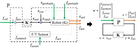
Consider the task of tracking a constant normal force by a position-controlled industrial robot. As depicted in Fig. 1, the force controller works to eliminate force tracking errors, , by “converting” them into position errors, , which are in turn tracked by the robot’s internal position controller. A well-developed force controller should be able to quickly track a reference force without going into instabilities. In this section, we discuss two low-level force controllers, namely the PID and CCS force controllers.
II-B1 PID force controller
The classical PID force controller is widely utilized in active force control, as it is relatively simple to change the overall system behavior in force tracking through each controller gain [15, 16]. Depending on the contact stiffness of the overall system, a variant of PID could produce a feasible force controller . It has been found that a pure integral controller provides the best performance for force control, with zero steady state error and a lower likelihood for instability [15]. This motivates the use of integral force controller in our subsequent analysis. Yet, the performance of an integral force controller is constrained by contact stiffnesses. Tuning higher integral gains will attain better performance in softer contacts but increases the risk of instability under stiffer material contacts. On the other hand, having low integral gains to accommodate stiffer contacts reduces the speed of assembly and could lead to excessive force overshoot. For assemblies requiring contact with multiple materials, overly conservative integral gains will also lead to non-optimal performance on softer materials.
II-B2 CCS force controller
The CCS force controller is based on a recently-proposed controller framework that searches for all stabilizing controllers to provide a desired force tracking nominal performance with a robust stability to a wide range of contact stiffnesses [2].
Briefly, the force control task is formulated as a multi-input-multi-output general control configuration using robust control theory as illustrated in Fig. 1. A matrix representation of the model could be as follows:
with derived from the system dynamics [17]. Then, the linear fractional transformation resulting in the closed-loop transfer matrix is:
Note that each element in corresponds to a transfer function from the exogenous inputs to the exogenous outputs . If we identify our performance requirements, such as noise attenuation, we can proceed to constrain and optimize each element to achieve our performance requirements. The aim of the CCS framework is then to search for the achievable closed-loop transfer matrix with the lowest cost and thereafter, derive the appropriate stable controller .
Notably, this force controller is a fixed controller that is optimally developed under constraints to achieve the desired nominal performance with robust stability across a wide range of contact stiffnesses. This implies that a CCS force controller, unlike classical PID controllers, can be tuned to perform nominally well for a soft material and still complete the assembly on stiffer materials at a similar assembly speed without going into instability.
III Improvements to the high-level assembly strategy
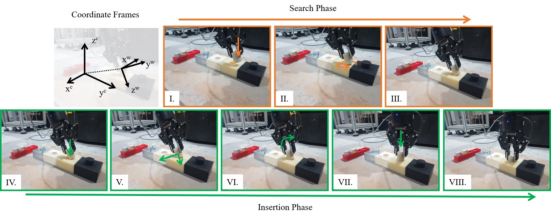
Here we present our high-level assembly strategy, which can be broken down into two phases of search and insertion as first proposed in [5], see illustration in Fig. 2 and flowchart in Fig. 3.

While the core of this high-level strategy is adapted from the literature, we propose two main innovations: (i) in the search phase, we propose a modulation of the sliding speed to mitigate the slip-stick friction on soft materials; (ii) in the insertion phase, we propose an explicit decomposition according to the number of point contacts, and use a different force set-point for each sub-phase.
In the sequel, we define , , and as the position vector, Cartesian force vector, and wrench force vector respectively.
III-A Search phase
The search phase encompasses states I-III. In state I, the peg is lowered to the hole surface with a tilt. This tilt enables further interpretation of force measurements and allow for greater changes in height along the search surface [5, 18]. The point contact also increases the speed of hole localization, especially for chamferless peg-in-hole assemblies [5]. Additionally, the tilt increases the cross-sectional area along the bending axis of the peg, reducing the severity of deformation and slip-stick in state II.
In state II, a hybrid position-force controller is utilized to perform an extensive spiral search, where the z-axis is controlled by a force controller while the planar x-y axes are position-controlled to trace an Archimedean spiral. The continuous spiral search path promises efficiency and robust coverage of the search space [7]. We first define as the initial position coordinates and let and be the velocity and pitch of search path respectively. Then, with a small , we can use Taylor’s first order approximation to obtain the estimated polar coordinates and . With and , the subsequent and position commands for spiral search are defined as:
We can determine the position of the hole when the peg dips significantly into the search plane. It is thus ideal for the force controller to maintain during the search. Also, to reduce the effects of slip-stick friction along the search plane, it is necessary for reference to kept small. Therefore, we command the normal reference force as . Yet, a lower reference induces a slower change along the z-axis when the peg is above the hole. In order to maintain even when above the hole, the search velocity should be constrained. Without compromising on the search efficiency outside the hole, we can decelerate to when , and accelerate it to a maximum of when .
We continue to store the and detected during the spiral search. Upon detection of a pre-defined difference in and , the hole is located and the peg is moved linearly towards in state III. Such an algorithm ensures robustness in hole detection for all possible initial contact points. Note that the threshold should be sufficiently large to account for any possible noise in sensor measurements or slight displacements in the setup. In theory, the threshold and pitch of the spiral search is related by the area covered within the isolines of the tilted peg depth profile. An oversized threshold will require a reduced pitch during the spiral search for successful hole localization.
III-B Insertion phase
For the insertion phase entailing states IV-VIII, all three axes switch to active force control. To ensure robustness in the insertion, each subsequent state is only fired after a steady state is attained in the measurements. Due to 2-finger clamping of the peg, the peg occasionally pivots about the contact point along the x-axis, thereby reducing the reliability of force measurements and control along that axis. Thus, the constraint for steady state along the x-axis is relaxed and the control along the x-axis is switched off once steady state is attained in subsequent states.
We first attempt to bring the peg to establish a stable and consistent contact with the hole. For that, we command the tilted peg to make 2-points contact at by utilizing compliant force control with in state IV. The peg will trace the edge of the hole to slide to its lowermost point at a fixed to establish 2-points contact. In our setup, a 2-points contact implies that the peg is centralized along the x-axis, and the hole center subsequently lies along the y-axis[19]. Next in state V, we aim to establish a stable 3-points contact to increase the robustness of our insertion strategy. By tracking forces and moving in the wrench coordinate frame, , we increase the likelihood of the peg remaining within the hole during motion.
After attaining 3-points contact, we proceed to align and insert the peg. In state VI, we conduct a position-controlled tilting of the peg by pivoting and maintaining contact of with the edge of the hole. Here, the fast performance of the force controller is especially important to prevent excessive force overshoot. Then, we center and insert the peg with in state VII. The ramp input mimics the careful insertion by humans and allows time to correct minor misalignments. Finally, the assembly is completed at state VIII.
IV Experiments
We evaluate the performance of the low-level force controllers expressed in Section II-B for peg-in-hole assembly using the high-level assembly strategy described in Section III. For that, we conduct two different sets of experiments with the CCS and PID force controllers.
IV-A Experimental setup
The assembly experiments are performed on a 6-axis position-controlled Denso VS-087 robotic arm. Its 2-fingered end-effector gripper is equipped with an ATI Force/Torque sensor, communicating at with an Ubuntu 16.04 computer. Chamferless pegs and insertion blocks are manufactured to an ISO 30 H9d9 fit, with a clearance of using four different materials. The height of the peg and hole is and respectively. The materials and corresponding overall contact stiffness are shown in Table I.
| Material | Stiffness () |
|---|---|
| Shore 30A silicone rubber | 10 |
| ABS plastic | 50 |
| Pine wood | 65 |
| Aluminum | 100 |
We subsequently design three force controllers: CCS, INTs (INTegral controller optimized for soft contacts), and INTh (INTegral controller optimized for hard contacts).
-
•
CCS force controller is designed using the CCS framework for a first order time response of with a nominal stiffness of and robust stability against contact stiffnesses up to ;
-
•
INTs is an integral force controller tuned with the same time response as the CCS controller at the nominal stiffness;
-
•
INTh is an integral force controller tuned to be stable against contact stiffnesses up to .
For the two experiments, we define the nominal contact point as where the lowest point of the peg coincides with the center of the hole at the end of state I. We evaluate the performance of the different force controllers with reference to this nominal contact point.
IV-B Experiment 1: CCS force controller
In our first experiment, we utilize the CCS force controller as the low-level force controller for assembly. We aim to show that our controller achieves robust insertion for random initial contact points in all four materials.
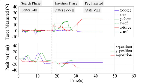
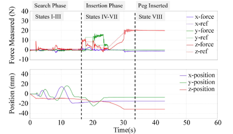
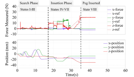
We perform a total of 48 trials – 12 on each material – with starting positions randomly sampled within a radius from the nominal contact point. Using the CCS force controller, we achieve robust assembly performance with a success rate, as shown in Table II. The average and maximum assembly durations after initial contact are and respectively. See also the video of the experiment at https://youtu.be/dgmsPGvF3d0, as well as the force and position measurements in Fig. 4.
| Material | Total no. of tests | Success rate (%) | Average time () |
|---|---|---|---|
| 30A silicone rubber | 12 | 100 | 26.2 |
| ABS plastic | 12 | 100 | 28.3 |
| Pine wood | 12 | 100 | 25.4 |
| Aluminum | 12 | 100 | 27.8 |
| Total | 48 | 100 | 26.9 |
IV-C Experiment 2: PID force controllers
For our second experiment, we utilize the two integral force controllers individually as the low-level force controller for assembly.
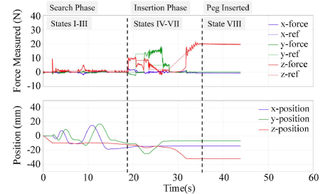
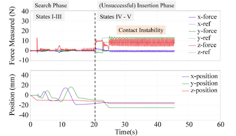
The experiments using the INTs force controller show that while the INTs force controller is viable for the silicone rubber environment, the assembly task cannot be completed with stiffer contacts. Fig. 5 demonstrates the INTs force controller going into instability at during the insertion phase of the ABS plastic assembly. Similar robustness issues are found during the pine wood and aluminum assembly.
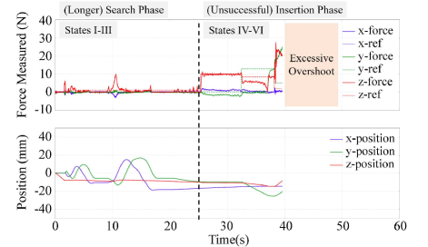
Using the INTh force controller, the assembly also fails as the force controller reacts slower to changes in forces, causing a longer settling time and excessive force overshoot. Fig. 6 shows that the INTh force controller has a slower response time in inducing changes in when the peg is above the hole. As such, using the INTh controller takes approximately longer than using the CCS controller for search after contact. It also takes approximately longer to establish stable 3-points contact as compared to the CCS controller during insertion. Finally, with the position-commanded tilt, the assembly experiences excessive force overshoot and is halted to avoid damaging parts.
IV-D Discussions
Our results highlight the limitations of conventional PID controllers in performing peg-in-hole assembly for environments of different stiffnesses. An integral force controller tuned for good nominal performance with silicone rubber goes into instability during peg-in-hole assembly in environments with higher contact stiffnesses (plastic, wood, aliminum). At the other end of the spectrum, an integral force controller tuned for stable contact with aluminum experiences a long settling time and large force overshoots during the assembly.
Meanwhile, the proposed CCS force controller tuned for good nominal performance in silicone rubber is able to perform peg-in-hole assembly similarly well in all four materials of different contact stiffnesses, without any gain tuning. It also performs better with shorter settling time and smaller force overshoot than a robustly-tuned integral force controller. Furthermore, the assembly strategy utilizing the CCS force controller also demonstrates high robustness to different initial contact points.
V Conclusions
In this paper, we build upon the recently-developed Convex Controller Synthesis (CCS) [2] to enable high-precision assembly across a wide range of surface stiffnesses without any surface-dependent tuning. Specifically, we have demonstrated peg-in-hole assembly with clearance, initial position uncertainties up to , and for four types of peg and hole materials – rubber, plastic, wood, aluminum – whose stiffnesses range from 10 to , using a single controller.
Our results highlight the performance and robustness of Convex Controller Synthesis over classical PID schemes. In future work, we shall explore the combination of CCS with Reinforcement Learning to generate versatile and robust assembly strategies.
ACKNOWLEDGMENT
Lee Y. J. W. thanks Hung Pham and Zhang Xu for their guidance.
References
- [1] J. Xu, Z. Hou, Z. Liu, and H. Qiao, “Compare contact model-based control and contact model-free learning: A survey of robotic peg-in-hole assembly strategies,” arXiv preprint arXiv:1904.05240, 2019.
- [2] H. Pham and Q.-C. Pham, “Convex controller synthesis for contact,” arXiv preprint arXiv:1909.04313, 2019.
- [3] F. Suárez-Ruiz, X. Zhou, and Q.-C. Pham, “Can robots assemble an ikea chair?” Science Robotics, vol. 3, no. 17, p. eaat6385, 2018.
- [4] M. H. Raibert, J. J. Craig et al., “Hybrid position/force control of manipulators,” Journal of Dynamic Systems, Measurement, and Control, vol. 103, no. 2, pp. 126–133, 1981.
- [5] H. Inoue, “Force feedback in precise assembly tasks,” Artificial Intelligence: An MIT perspective, MIT Press, pp. 219–241, 1974.
- [6] W. S. Newman, Y. Zhao, and Y.-H. Pao, “Interpretation of force and moment signals for compliant peg-in-hole assembly,” in Proceedings 2001 ICRA. IEEE International Conference on Robotics and Automation (Cat. No. 01CH37164), vol. 1. IEEE, 2001, pp. 571–576.
- [7] S. R. Chhatpar and M. S. Branicky, “Search strategies for peg-in-hole assemblies with position uncertainty,” in Proceedings 2001 IEEE/RSJ International Conference on Intelligent Robots and Systems. Expanding the Societal Role of Robotics in the the Next Millennium (Cat. No. 01CH37180), vol. 3. IEEE, 2001, pp. 1465–1470.
- [8] L. Bodenhagen, A. R. Fugl, M. Willatzen, H. G. Petersen, and N. Krüger, “Learning peg-in-hole actions with flexible objects.” in ICAART (1), 2012, pp. 624–631.
- [9] B. Bona and M. Indri, “Friction compensation in robotics: an overview,” in Proceedings of the 44th IEEE Conference on Decision and Control. IEEE, 2005, pp. 4360–4367.
- [10] I. F. Jasim, P. W. Plapper, and H. Voos, “Contact-state modelling in force-controlled robotic peg-in-hole assembly processes of flexible objects using optimised gaussian mixtures,” Proceedings of the Institution of Mechanical Engineers, Part B: Journal of Engineering Manufacture, vol. 231, no. 8, pp. 1448–1463, 2017.
- [11] J. Kim and H. S. Cho, “Visual sensor-based measurement for deformable peg-in-hole tasks,” in Proceedings 1999 IEEE/RSJ International Conference on Intelligent Robots and Systems. Human and Environment Friendly Robots with High Intelligence and Emotional Quotients (Cat. No. 99CH36289), vol. 1. IEEE, 1999, pp. 567–572.
- [12] X. Yanchun, B. Yuewei, and H. Yafei, “Assembly strategy study on the elastic deformable peg in hole,” in 2010 The 2nd International Conference on Industrial Mechatronics and Automation, vol. 1. IEEE, 2010, pp. 193–197.
- [13] T. Inoue, G. De Magistris, A. Munawar, T. Yokoya, and R. Tachibana, “Deep reinforcement learning for high precision assembly tasks,” in 2017 IEEE/RSJ International Conference on Intelligent Robots and Systems (IROS). IEEE, 2017, pp. 819–825.
- [14] J. Luo, E. Solowjow, C. Wen, J. A. Ojea, A. M. Agogino, A. Tamar, and P. Abbeel, “Reinforcement learning on variable impedance controller for high-precision robotic assembly,” in 2019 International Conference on Robotics and Automation (ICRA). IEEE, 2019, pp. 3080–3087.
- [15] R. Volpe and P. Khosla, “A theoretical and experimental investigation of explicit force control strategies for manipulators,” IEEE Transactions on Automatic Control, vol. 38, no. 11, pp. 1634–1650, 1993.
- [16] G. F. Franklin, J. D. Powell, A. Emami-Naeini, and J. D. Powell, Feedback control of dynamic systems. Addison-Wesley Reading, MA, 1994, vol. 3.
- [17] S. Skogestad and I. Postlethwaite, Multivariable feedback control: analysis and design. Wiley New York, 2007, vol. 2.
- [18] T. Lozano-Perez, M. T. Mason, and R. H. Taylor, “Automatic synthesis of fine-motion strategies for robots,” The International Journal of Robotics Research, vol. 3, no. 1, pp. 3–24, 1984.
- [19] K. Sharma, V. Shirwalkar, and P. K. Pal, “Intelligent and environment-independent peg-in-hole search strategies,” in 2013 International Conference on Control, Automation, Robotics and Embedded Systems (CARE). IEEE, 2013, pp. 1–6.