Backward Raman scattering in relativistic electron beam and intense THz light
Abstract
A new type of the THz laser is proposed. A coherent tera-hertz light is emitted through the backward Raman scattering between a visible light laser and a relativistic electron beam. The threshold conditions for the laser intensity and the electron beam density are identified. This scheme may lead to one of the most intense tera-hertz coherent light sources.
pacs:
42.55.Vc, 42.65.Ky, 52.38.-r, 52.35.HrAn intense and compact THz light source is critical component in the biomedical image, the tomography, the molecular spectroscopy, the tele-communication and many others Siegel (2002, 2004, 2007); Booske (2008); Cooper et al. (2008); Nagel et al. (2002); Yamamoto et al. (2004). Many THz light sources have been invented van Tilborg et al. (2005); Sheng et al. (2004); Reimann (2007); Chu et al. (1998); Kreischer and Temkin (1987); Bratman et al. (2009); Kim et al. (2009); Faist et al. (1994); Tonouchi (2009); Carr et al. (2002); Williams (2002); Colson (1985); Son and Moon (2012); Gallardo (1988); Son et al. (2012), but even the most advanced ones are neither practical nor intense enough; The free electron laser Carr et al. (2002); Williams (2002); Colson (1985) needs expensive magnets and accelerators, the quantum cascade laser Faist et al. (1994); Tonouchi (2009) cannot produce intense THz light neither be operated in the room temperature and the gyrotron suffers the scale problem unless the magnetic field is ultra intense Chu et al. (1998); Kreischer and Temkin (1987); Bratman et al. (2009); Kim et al. (2009). The current inability to produce the power (intensity) high enough for various applications aforementioned is referred as “THz gap”.
In this paper, the author proposes a new process of the THz light generation by amplifying the interaction between an intense visible-light laser and a relativistic electron beam via the backward Raman scattering (BRS). To my knowledge, it is the first scheme, in which a visible light wave is shifted down into THz light via the BRS, potentially overcoming various difficulties of the current technoloiges. In the visible-light laser compression Malkin and Fisch (2007) and the inertial confinement fusion research Tabak et al. (1994), the BRS has been demonstrated to be much stronger than the scattering by an individual electron; As an illustration, considering the electron plasma with the density particles per cubic centimeter and the visible-light laser with the intensity of watt per square centimeter, the BRS is times larger than the conventional Thomson scattering. If utilized produently, a light source based this strong scattering can exceed the free electron laser by order of magnitude, which is the main motiviation of this work. It is worthwhile to point out that so far, the most powerful current THz light source is based on the Thomson scattering.
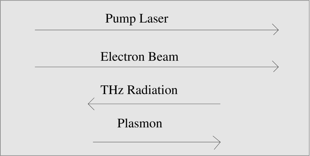
The author considers the situation when an intense visible light laser co-traveling with a relativistic electron beam excites a Langmuir wave and the BRS between the Langmuir wave and the laser emits a THz light in the opposite direction to the electron beam (Fig. 1). In this case, the laser will be shifed down to the THz light via the relativistic Doppler’s effect. The analysis in this paper suggests that the scheme cold produce the most powerful and efficient THz light source and even possibly a cheap one. The linear analysis of the 1-D BRS is provided analytically and the range of the physical parameters (Table 1), at which the current scheme becomes most practical, are estimated. One-dimensional (1-D) simulation of the pulse amplification (Fig. 2) is performed to validate its plausibility.
To begin with, consider a relativistic electron beam and a co-traveling laser (pump laser). Let us denote the beam density in the laboratory frame by and the beam relativistic factor by , where is the velocity of the electron beam. In the co-traveling frame, the electron density becomes due to the length dilation. The BRS between the laser (the pump pulse) and the electron beam could emit the THz light (the seed pulse). The 1-D BRS three-wave interaction in the co-traveling frame is McKinstrie and Simon (1986):
| (1) | |||
where is the ratio of the electron quiver velocity of the pump pulse () and the seed pulse () relative to the speed of light , is the electric field of the seed (pump) pulse, is the Langmuir wave amplitude, () is the inverse bremsstrahlung rate of the pump (seed), is the plasmon decay rate, for , , () is the frequency of the pump (seed) laser and is the plasmon frequency. In the co-traveling frame, the wave vector (frequency) of a photon satisfies the usual dispersion relation, , where and are the photon wave frequency and the corresponding vector, and is the plasmon frequency. Denote the wave vector and the frequency of the pump laser (seed pulse or THz light) in the co-traveling frame as and ( and ) and their laboratory frame counterparts as and ( and ). The Lorentz transformation leads to the following relationship:
| (2) | |||||
| (3) | |||||
| (4) | |||||
| (5) |
The energy and momentum conservation of Eq. (1) are given as
| (6) |
where is the wave vector of the plasmon. With a given pump frequency , () is determined from Eq. (2), () is determined from Eq. (6), and, finally, () is determined from Eqs. (4) and (5). In the limiting case , or
| (7) |
where and . Eq. (7) describes the frequency down-shift of the visible-light pump laser into the THz light, via the relativistic Doppler effect. For instance, if , the down-shifted frequency would be THz for the CO2 laser whose frequency is 30 THz.
The BRS growth rate can be obtained from Eq. (1). When and , the linearization of Eq. (1), in the expansion of , leads to
| (8) |
If and , the growth rate, the imaginary part of the solution of Eq. (8), is . In the limiting case , the Lorentz transformation prescribes and , resulting in
| (9) |
Denoting the electron beam length as and the laser length as , the beam length in the co-traveling frame increases to and the laser length increases to so that the interaction time between the beam and the laser is . The gain-per-length is therefore estimated as
| (10) |
| Type | Freq | |||||||
|---|---|---|---|---|---|---|---|---|
| N | 3.0 | 1.00 | 5.0 | 0.020 | 0.0245 | 40.874 | 81.748 | 2.56 |
| N | 3.0 | 5.0 | 0.6324 | 0.775 | 1292 | 2585 | 2.56 | |
| N | 3.0 | 0.01 | 5.0 | 0.0006 | 0.0008 | 1.29 | 2.58 | 2.56 |
| N | 8.3 | 1.0 | 3.0 | 0.02 | 0.0359 | 35.97 | 71.95 | 7.11 |
| N | 8.3 | 3.0 | 0.63 | 1.14 | 1137 | 2275 | 7.1 | |
| N | 8.3 | 0.01 | 3.0 | 0.002 | 0.0036 | 3.597 | 7.19 | 7.1 |
| C | 0.83 | 1.0 | 3.0 | 0.2 | 0.113 | 113.75 | 227.5 | 0.007 |
| C | 0.83 | 30 | 3.0 | 1.0 | 0.62 | 623 | 1246 | 0.007 |
| C | 0.83 | 3.0 | 0.006 | 0.0036 | 3.59 | 7.2 | 0.007 | |
| C | 1.88 | 1.0 | 2.0 | 0.2 | 0.15 | 103 | 206 | 0.016 |
| C | 1.88 | 0.01 | 2.0 | 0.02 | 0.015 | 10.28 | 20.56 | 0.016 |
An estimation of the energy conversion efficiency of the pump to the seed pulse is as follows. Practical applications of the BRS compression of the visible-light lasers have demonstrated that a significant portion of the pump energy can be converted to the seed pulse Malkin et al. (2000); Malkin and Fisch (2007); Russell et al. (1999); Sakharov and Kirsanov (1994); Clark and Fisch (2003); Son and Moon (2011). Denote the total energy of the pump laser by , which becomes in the co-traveling frame, and denote the conversion efficiency in the co-traveling frame by . Then, the energy transferred from the pump to the seed is , which is in the laboratory frame. Therefore, the conversion efficiency in the laboratory frame is
| (11) |
The CO2 laser has the wavelength of and the Nd:YAG laser has the wavelength of . From Eq. (7), for a fixed , the required relativistic factor for the CO2 laser should be lower than the Nd:YAG laser by a factor of and thus the conversion efficiency for the CO2 laser will be larger than the Nd:YAG laser by a factor 10 for the same . For , the conversion efficiency for the CO2 laser can be as high as a few percents, assuming that is a few tens of percents.
In order for the current scheme to work, there exist a few necessary conditions for the laser and the electron beam. One necessary condition is for a sufficient amplification or
| (12) |
which is readily satisfied by currently available intense visible-light laser Strickland and Mourou (1985); Perry and Mourou (1994); Mourou et al. (1997); Brabec and Krausz (2000). Another necessary condition for the electron beam density is , as only the plasmons with are collective waves. In the limiting case , the condition is
| (13) |
where and . In addition, the wave vector of the Langmuir wave should be larger than the Debye length
| (14) |
where . The condition given by Eqs. (13) and (14) estimates the minimum electron beam density for the BRS compression for a given electron temperature. Note that much higher density can be achieved through the current electron accelerator or dense electron beams Mangles et al. (2004); Tatarakis et al. (2003); Tabak et al. (1994); Son and Fisch (2005, 2004) while the electron temperature is low enough to satisfy Eq. (14).

The estimations for various electron beams and lasers are provided in the Table 1. The Table suggests that the proposed scheme is plausible for a wide range of frequencies, the growth rate (the gain-per-length) can be as high as () and the requirement of the laser intensity, , is moderate. If for the case of the Nd:YAG laser as in Table 1, the electron quiver velocity becomes marginally relativistic and the full relativistic treatment is necessary McDermott et al. (1978), which is ignored in this paper.
In Fig. (2), a 1-D simulation of Eq. (1) is performed, where the pump laser is the CO2 laser with (). The pump laser (the seed pulse) moves from the left (right) to the right (left) and the THz pulse extracts the energy from the pump laser via the BRS, resulting the energy gain of the THz pulse by a factor of 1000. In this example, the pump laser has the intensity of () in the co-moving frame (the laboratory frame); the intensity of the pump laser (THz pulse) is higher (lower) by 36 times in the laboratory frame than in the co-moving frame due to the Doppler’s effect. In the simulation shown in Fig. (2), the final peak intensity of the THz pulse in the co-moving frame is comparable to the intensity of the pump laser; the attained peak intensity of the THz pulse is in the laboratory frame, which is 0.1 percent of the laser pump intensity. Various simulation suggests that the attained peak intensity of the THz pulse in the laboratory frame can be as high as the the laser pump intensity.
Fig. (2) illustrates that the final peak intensity of the THz light can be very high; The THz light with such high intensity can be very useful for the spectroscope and the dynamic imaging application, noting the fact that the intensity from the current availble light sources is at least million times smaller.
To summarize, a new scheme of the THz light source is proposed based the backward Raman scattering. Detailed estimation of the optimal parameter range for the laser beam and the electron beam are provide in Table 1 and one example on the 1-D simulation of Eq. (1) is provided in Fig. (2). The most intense and powerful coherent THz light source can be manufactured based on the current scheme; The gain-per-length can be as high as 1000 per centimeter while the current strongest THz laser has the gain-per-length much less than 1 per centimeter, the conversion efficiency of converting the input laser energy into the THz light is as high as a few percents while the current most efficient light source has the conversion efficiency less than 0.01 percent, the THz light energy per one laser shot can be as high as a few J while the most powerful THz laser can produce the enery-per-shot much lower than 0.001 J and, finally, the peak THz intensity can be comparable the pump laser intensity. In addition, because it does not need expensive magnets or high quality electron beam, the disclosed light source has advantages in the compactness, the mobility and the operating (construction) cost. While some researches have attempted to shift the visible light laser up to the XUV regime via the BRS McDermott et al. (1978); Esarey and Sprangle (1992); Sprangle and Drobot (1979), the new idea for the scheme presented here is that the visible-light laser is shifted down to the THz regime via the BRS.
There are technical issues to consider in the realization of the proposed scheme. The performance of the proposed scheme relies on the quality of the electron beam such as the uniformity and the time duration in which the beam maintains its quality. Also, a rather intense seed THz pulse would be needed in order to extract the significant fraction of the pump pulse energy. However, even if the difficulties mentioned compromises the efficiency of the scheme proposed to some degree, its prospect as a powerful THz light source remains high.
References
- Siegel (2002) P. H. Siegel, Microwave Theory and Techniques, IEEE Transaction on 50, 910 (2002).
- Siegel (2004) P. H. Siegel, Microwave Theory and Techniques, IEEE Transaction on 52, 2438 (2004).
- Siegel (2007) P. H. Siegel, Antennas and Propagation, IEEE Transactions on 55, 2957 (2007).
- Booske (2008) J. H. Booske, Physics of Plasmas 15, 055502 (2008).
- Cooper et al. (2008) K. B. Cooper, R. J. Dengler, G. Chattopadhyay, E. Schlecht, J. Gill, A. Skalare, I. Mehdi, and P. H. Siegel, IEEE, Microwave and Wireless Components Letters 18, 64 (2008).
- Nagel et al. (2002) M. Nagel, P. H. Bolivar, M. Brucherseifer, H. Kurz, A. Bosserhoff, and R. Buttner, Appl. Phys. Lett. 80, 154 (2002).
- Yamamoto et al. (2004) K. Yamamoto, M. Yamaguchi, F. Miyamaru, M. Tani, M. Hangyo, T. Ikeda, A. Matsushita, K. Koide, M. Tatsuno, and Y.Minami, Jpn. J. Appl. Phys. 43, L414 (2004).
- van Tilborg et al. (2005) J. van Tilborg, P. A. Michel, C. B. Schroeder, C. Toth, C. G. R. Geddes, and B. A. Shadwick, Plasma Science. IEEE Transaction on 33, 22 (2005).
- Sheng et al. (2004) Z. Sheng, H. Wu, K. Li, and J. Zhang, Phys. Rev. E 69, 025401 (2004).
- Reimann (2007) K. Reimann, Reports on Progress in Physics 70, 1597 (2007).
- Chu et al. (1998) K. R. Chu, H. Y. Chen, C. L. Hung, T. H. Chang, L. R. Barnett, S. H. Chen, and T. T. Yang, Phys. Rev. Lett. 81, 4760 (1998).
- Kreischer and Temkin (1987) K. E. Kreischer and R. J. Temkin, Phys. Rev. Lett. 59, 547 (1987).
- Bratman et al. (2009) V. L. Bratman, Y. L. Kalynov, and V. N. Manuilov, Phys. Rev. Lett. 102, 245101 (2009).
- Kim et al. (2009) J. Kim, S. Jeon, Y. Jin, D. Kim, and S. Jung, J. Vac. Sci. Technol. B 27, 687 (2009).
- Faist et al. (1994) J. Faist, F. Capasso, D. L. Sivco, C. Sirtori, A. L. Hutchinson, and A. Y. Cho, Science 264, 553 (1994).
- Tonouchi (2009) M. Tonouchi, Terahertz Science and Technology 2, 90 (2009).
- Carr et al. (2002) G. L. Carr, M. C. Martin, W. R. Mckinney, K. Jordan, G. R. Neil, and G. P. Williams, Nature 420, 153 (2002).
- Williams (2002) G. P. Williams, Review of Scientific Instruments 73, 1461 (2002).
- Colson (1985) W. B. Colson, Nucl. Inst. Meth. Phys. A 237, 1 (1985).
- Son and Moon (2012) S. Son and S. J. Moon, Phys. Plasmas 19, 063102 (2012).
- Gallardo (1988) J. C. Gallardo, IEEE J. Quantum. Elec. 24, 1557 (1988).
- Son et al. (2012) S. Son, S. J. Moon, and J. Y. Park, Optics Letters 37, 5172 (2012).
- Malkin and Fisch (2007) V. M. Malkin and N. J. Fisch, Phys. Rev. Lett. 99, 205001 (2007).
- Tabak et al. (1994) M. Tabak, J. Hammer, M. E. Glinsky, W. L. Kruerand, S. C. Wilks, J. Woodworth, E. M. Campbell, M. J. Perry, and R. J. Mason, Physics of Plasmas 1, 1626 (1994).
- McKinstrie and Simon (1986) C. J. McKinstrie and A. Simon, Phys. Fluids 29, 1959 (1986).
- Malkin et al. (2000) V. M. Malkin, G. Shvets, and N. J. Fisch, Phys. Rev. Lett. 84, 1208 (2000).
- Russell et al. (1999) D. A. Russell, D. F. DuBois, and H. A. Rose, Phys. Plasmas 6, 1294 (1999).
- Sakharov and Kirsanov (1994) A. S. Sakharov and V. I. Kirsanov, Phys. Rev. E 49, 3274 (1994).
- Clark and Fisch (2003) D. S. Clark and N. J. Fisch, Phys. Plasmas 10, 4837 (2003).
- Son and Moon (2011) S. Son and S. J. Moon, Phys. Plasmas 18, 084504 (2011).
- Strickland and Mourou (1985) D. Strickland and G. Mourou, Phys. Fluids 55, 447 (1985).
- Perry and Mourou (1994) M. D. Perry and G. Mourou, Science 264, 917 (1994).
- Mourou et al. (1997) G. Mourou, C. P. J. Barty, and M. Perry, Physics Today 51, 22 (1997).
- Brabec and Krausz (2000) T. Brabec and F. Krausz, Rev. Mod. Phys. 72, 545 (2000).
- Mangles et al. (2004) S. P. D. Mangles, C. D. Murphy, Z. Najmudin, A. G. R. Thomas, J. L. Collier, A. E. Dangor, E. J. Divall, P. S. Foster, J. G. Gallacher, C. J. Hooker, et al., Nature 431, 535 (2004).
- Tatarakis et al. (2003) M. Tatarakis, F. N. Beg, E. L. Clark, A. E. Dangor, R. D. Edwards, R. G. Evans, T. J. Goldsack, K. W. D. Ledingham, P. A. Norreys, M. A. Sinclair, et al., Phys. Rev. Lett. 90, 175001 (2003).
- Son and Fisch (2005) S. Son and N. J. Fisch, Phys. Rev. Lett. 95, 225002 (2005).
- Son and Fisch (2004) S. Son and N. J. Fisch, Phys. Lett. A 329, 16 (2004).
- McDermott et al. (1978) D. B. McDermott, T. C. Marshall, S. P. Schlesinger, R. K. Parker, and V. L. Granatstein, Phys. Rev. Lett. 41, 1368 (1978).
- Esarey and Sprangle (1992) E. Esarey and P. Sprangle, Phys. Rev. A 45, 5872 (1992).
- Sprangle and Drobot (1979) P. Sprangle and A. T. Drobot, Journal of Applied Physics 50, 2652 (1979).