Theoretical investigation of a miniature microwave driven plasma jet

Michael Klute1    Horia-Eugen Porteanu2    Ilija Stefanović3    Wolfgang Heinrich2    Peter Awakowicz3    Ralf Peter Brinkmann1 1Institute for Theoretical Electrical Engineering, Ruhr University Bochum, D-44780 Bochum, Germany 2Microwave Department, Ferdinand-Braun-Institut, Berlin Germany 3Electrical Engineering and Plasma Technology, Ruhr University Bochum, Germany
Abstract

Microwave and radio frequency driven plasmas jets play an important role in many technical applications. They are usually operated in a capacitive mode known as E-mode. As a new plasma source the MMWICP (Miniature Micro Wave ICP) has been proposed, a small scale plasma jet with inductive coupling based on a specially designed resonator that acts as an LC-resonance circuit. This work presents a theoretical model of the new device, based on a series representation of the electromagnetic field in the resonator and the volume integrated (global) model for the loss processes within the plasma. An infinite number of modes can be found ordered by the azimuthal wave number m. These modes essentially determine the electromagnetic behavior of the system and differ from ordinary cavity modes. The mode m=0𝑚0m=0 can be identified with the inductive mode and is called H-mode, the mode m=1𝑚1m=1 is the capacitive mode and is called E-mode. Both modes refer to different operating regimes, which are separated by different values of the plasma parameters. In a second step the matching network and its characteristics are taken into account in order to find stable equilibrium points and possible hysteresis effects. As main result, the feasibility of inductive power coupling for the MMWICP resonator is shown.

I Introduction

Plasma processes can be classified into “direct” and “remote”. In direct plasma processes, the generation and application of the plasma are co-located: A work-piece is introduced into a plasma chamber and processed therein. In remote plasma processes, plasma generation and plasma application are spatially separated. In the source, the plasma is only generated; from there it emerges as a beam of energetic particles and strikes the object that is being treated. Remote plasma processes have significant advantages: The source and the remote plasma are almost independent in their properties and can be optimized separately. The sources themselves are often quite small (“miniaturized”), and can be handled very flexibly. They can be designed for a wide pressure range: low pressure (about 101010-103Pasuperscript103Pa10^{3}\,\mathrm{Pa}) is of interest, e.g., for plasma enhanced thin film deposition, atmospheric pressure (105Pasuperscript105Pa10^{5}\,\mathrm{Pa}) allows medical and environmental applications. Among the sources suitable for remote processes, radio frequency (RF) or microwave (MW) operated plasma jets play a special role. They are usually operated in a capacitive, or E-Mode: the RF or MW power is applied to the electrodes, resulting in a strong electric field in the interior of the jet. If the field strength exceeds the breakdown value, the discharge ignites and a plasma forms. It comes to the formation of a quasi neutral bulk and a strongly electron depleted boundary sheath. Capacitive coupling allows plasma jets with a simple structure and favorable ignition behavior. However, it also has considerable disadvantages: in the operating state, only the bulk voltage contributes to the electron heating; this limits the efficiency and thus also the achievable plasma density. On the other hand, the voltage across the sheath increases the kinetic energy of the ions, which are striking the electrodes. The high ion energy also causes a strong erosion and heating of the electrodes, up to the ignition of a parasitic arc. These disadvantages motivate the search for an alternative form of coupling with focus on inductive coupling. Instead of using electrodes, the typical design of an inductively coupled plasma (ICP) reactor consists of either a planar or helical coil, which is located outside the plasma chamber and driven by a RF or MW signal. A time varying magnetic field is created by the coil. The magnetic field in turn induces a strong current within the plasma, which is gaining energy in this way. The inductive coupling is also known as H-Mode. ICPs show much brighter light emissions, up to 10-times higher electron densities and a lower plasma potential ref1 . In the same time they show lower ion energies, resulting in less erosive effects, such as ion sputtering ref2 ,ref3 . Successful examples for small scale systems are RF induction lamps ref4 , ref5 . Attempts have been made to realize inductive coupling also for plasma jets. A successful example for a large scale ICP jet is the induction-coupled plasma torch ref6 . First attempts to realize small scale ICP jets have shown to be only partially successful; doubts were expressed by the authors if the H-mode could be achieved or not ref7 -ref9 . It is interesting to look at the following expression, taken from the textbook by Lieberman and Lichtenberg ref10 : The power, PRFsubscript𝑃𝑅𝐹P_{RF}, coupled to an MW driven ICP with chamber radius R1subscript𝑅1R_{1} and a balanced, cylindrical geometry (radius R1subscript𝑅1R_{1} \approx height H𝐻H) can be expressed as a function of skindepth λssubscript𝜆𝑠\lambda_{s}, inductor current I𝐼I, effective scattering frequency ν𝜈\nu, permeability of free space μ0subscript𝜇0\mu_{0} and winding number N𝑁N:

PRF={μ0νN2I2R13/λs2for λsR1μ0νN2I2λsfor λsR1.subscript𝑃𝑅𝐹casessubscript𝜇0𝜈superscript𝑁2superscript𝐼2superscriptsubscript𝑅13superscriptsubscript𝜆𝑠2greater-than-or-equivalent-tofor subscript𝜆𝑠subscript𝑅1subscript𝜇0𝜈superscript𝑁2superscript𝐼2subscript𝜆𝑠less-than-or-similar-tofor subscript𝜆𝑠subscript𝑅1\displaystyle P_{RF}=\begin{cases}\mu_{0}\nu N^{2}I^{2}R_{1}^{3}/\lambda_{s}^{2}&\text{for }\lambda_{s}\gtrsim R_{1}\\ \mu_{0}\nu N^{2}I^{2}\lambda_{s}&\text{for }\lambda_{s}\lesssim R_{1}.\end{cases} (1)

Apparently a small scale ICP can only be operated efficiently if the chamber radius R𝑅R and the skindepth λssubscript𝜆𝑠\lambda_{s} and are at least of comparable size (or better λs<Rsubscript𝜆𝑠𝑅\lambda_{s}<R ). Thus, high densities are required as λssubscript𝜆𝑠\lambda_{s} is proportional to ne1/2superscriptsubscript𝑛𝑒12n_{e}^{-1/2}. Here nesubscript𝑛𝑒n_{e} denotes the plasma electron density. Often the winding-number N𝑁N was increased to improve the coupling efficiency. This leads to a higher voltage drop at the coil and a decreased resonance frequency, limiting the parameter range of the discharge. In a previous work of Porteanu et al. ref1 a different approach was developed. A LC-resonance circuit was implemented into a resonator. The design is depicted in Figs 1 and 3. The typical voltage drop (due to the coil) is strongly limited for this design. Thus, the occurrence of an undesired capacitive discharge can be suppressed. The system losses are minimized and an optimum of the energy transfer to the plasma is achieved. Some experimental results have been gathered already from a prototype model ref1 , ref11 , ref12 .

The purpose of this paper is to theoretically examine the prototype with focus on its electromagnetic behavior. In chapter 2 a detailed description of the reactor prototype and its electrical matching network is given. In chapter 3 an analytical description of the electromagnetic fields is given based on a series representation. The results differ from ordinary cavity modes. A linear model for the power losses is added to consider the power balance of the system. In chapter 4 fundamental insights into the system is presented regarding stable operating points, operating regimes, hysteresis effects and the pattern of field lines. The terms E- and H-mode will be applied to the system. The general feasibility of the inductive coupling for a small scale plasma jet is shown. A comparison to existing experiments is limited to the electromagnetic aspects as experimental results are only available for nitrogen yet. The paper concludes with chapter 5, where the results are summarized, discussed and an outlook to further modifications is given.

II The demonstrator and its idealization

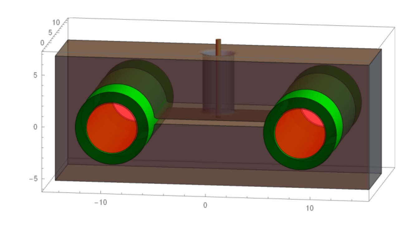
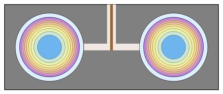
A schematic drawing of the plasma reactor is shown in Fig 3. The design is based on a resonator made of a solid block of copper with a length of l1=34mmsubscriptl134mm\textrm{l}_{1}=34\,\textrm{mm}, a height of h=10mmh10mm\textrm{h}=10\,\textrm{mm} and a depth of l2=8mmsubscriptl28mm\textrm{l}_{2}=8\,\textrm{mm} ref1 . There are two parallel cavities with radius R=3.5mmR3.5mm\textrm{R}=3.5\,\textrm{mm} in the copper block. Both are connected by a gap of length ls=11mmsubscriptl𝑠11mm\textrm{l}_{s}=11\,\textrm{mm} and width ds=0.22mmsubscriptd𝑠0.22mm\textrm{d}_{s}=0.22\,\textrm{mm}. Two dielectric tubes with wall thickness d=1mmd1mm\textrm{d}=1\,\textrm{mm}, through which a gas flows, are guided through the parallel cavities. The plasma is ignited within the tubes. The resonator is shielded with a solid 8mm8mm8\,\textrm{mm} thick housing of aluminum. The resonator is driven by an external MW amplifier with frequency f=2.45×10⁹Hz𝑓2.45superscript109Hzf=2.45\times 10^{9}\,\textrm{Hz} (angular frequency ω=1.54×10¹⁰s1𝜔1.54superscript1010superscripts1\omega=1.54\times 10^{10}\,\textrm{s}^{-1}) and an amplitude expressed as output voltage uSsubscript𝑢Su_{\textrm{S}}). Due to the ratio between the the dimensions (2×R=7mm2R7mm2\times\textrm{R}=7\,\textrm{mm}) and the wavelength of the microwave signal (λRF12cmsubscript𝜆RF12cm\lambda_{\textrm{RF}}\approx 12\,\textrm{cm}) cavity modes are not excited in the resonator.

For the proposed theoretical description the following idealizations is made: An electromagnetic regime will be assumed within the resonator cavities and an electrostatic regime will be assumed within the gap connecting the resonators cavities. In particular, the system of the two cavities and the gap in between is considered as a system of coupled waveguides; electromagnetic effects can not propagate into the gap. In conclusion a simplified description using lumped elements is possible: Both cavities are regarded as coils with one winding and with the individual inductance LR=6nHsubscript𝐿𝑅6nHL_{R}=6\,\textrm{nH}, while the gap is regarded as a capacitor with capacity Cres=3pFsubscript𝐶res3pFC_{\textrm{res}}=3\,\rm{pF}. These elements form an idealized LC-circuit with resonance frequency fRes2.2×109Hzsubscript𝑓Res2.2superscript109Hzf_{\textrm{Res}}\approx 2.2\times 10^{9}\textrm{Hz}. All interactions between the two cavities and the gap are limited to the lumped element model.

During operation the jet works as a ”‘double jet”’ with two parallel discharges and two separate plasma effluents. As the gap area is limited to an electrostatic regime, no electromagnetic interaction between the two parallel discharges are taken into account. Therefore the full electromagnetic calculation is performed for one discharge only (”‘single jet”’ instead of ”‘double jet”’). In addition, inside the cavity three zones are defined with respect to the radius r. In the range r=0(Rδd)𝑟0𝑅𝛿𝑑r=0\ldots(R-\delta-d) it is the plasma bulk, r=(Rδd)(Rd)𝑟𝑅𝛿𝑑𝑅𝑑r=(R-\delta-d)\ldots(R-d) represents the plasma sheath zone and r=(Rd)R𝑟𝑅𝑑𝑅r=(R-d)\ldots R represents the dielectric zone. Furthermore, the electromagnetic field is assumed to be invariant along the axis of the tube/gasflow. This follows from the aspect ratio of the resonator (R<l2𝑅subscriptl2R<\textrm{l}_{2}) in general, as well as from the ratio between l2subscriptl2\textrm{l}_{2} and the skin depth in particular (λsl2much-less-thansubscript𝜆𝑠subscriptl2\lambda_{s}\ll\textrm{l}_{2}).

An expression for the complex admittance of one single discharge YP(ne,ω)subscript𝑌Psubscript𝑛e𝜔Y_{\textrm{P}}(n_{\textrm{e}},\omega) is derived from calculations, so the plasma can be incorporated into the lumped element model. In order to efficiently connect the resonator to a microwave source (with the inner impedance of Z0=50ΩsubscriptZ050Ω\textrm{Z}_{0}=50\,\Omega), an impedance transformation is required. Such a transformation is realized by the external inductances Lsersubscript𝐿serL_{\textrm{ser}} and Lparsubscript𝐿parL_{\textrm{par}} and the resonators capacitor Cressubscript𝐶resC_{\textrm{res}}, which are forming a matching network. The resulting admittance YS(ω,ne)subscript𝑌S𝜔subscript𝑛eY_{\textrm{S}}(\omega,n_{\textrm{e}}) of a ”‘single jet”’-system follows from the circuit in the experiment and is given by:

YS(ω,ne)=(1(YP(nne,ω)+iωCres)1+iωLser+1iωLpar).subscript𝑌S𝜔subscript𝑛e1superscriptsubscript𝑌Psubscript𝑛ne𝜔𝑖𝜔subscript𝐶res1𝑖𝜔subscript𝐿ser1𝑖𝜔subscript𝐿par\displaystyle Y_{\textrm{S}}(\omega,n_{\textrm{e}})=\left(\frac{1}{(Y_{\textrm{P}}(n_{\textrm{ne}},\omega)+i\omega C_{\textrm{res}})^{-1}+i\omega L_{\textrm{ser}}}+\frac{1}{i\omega L_{\textrm{par}}}\right). (2)

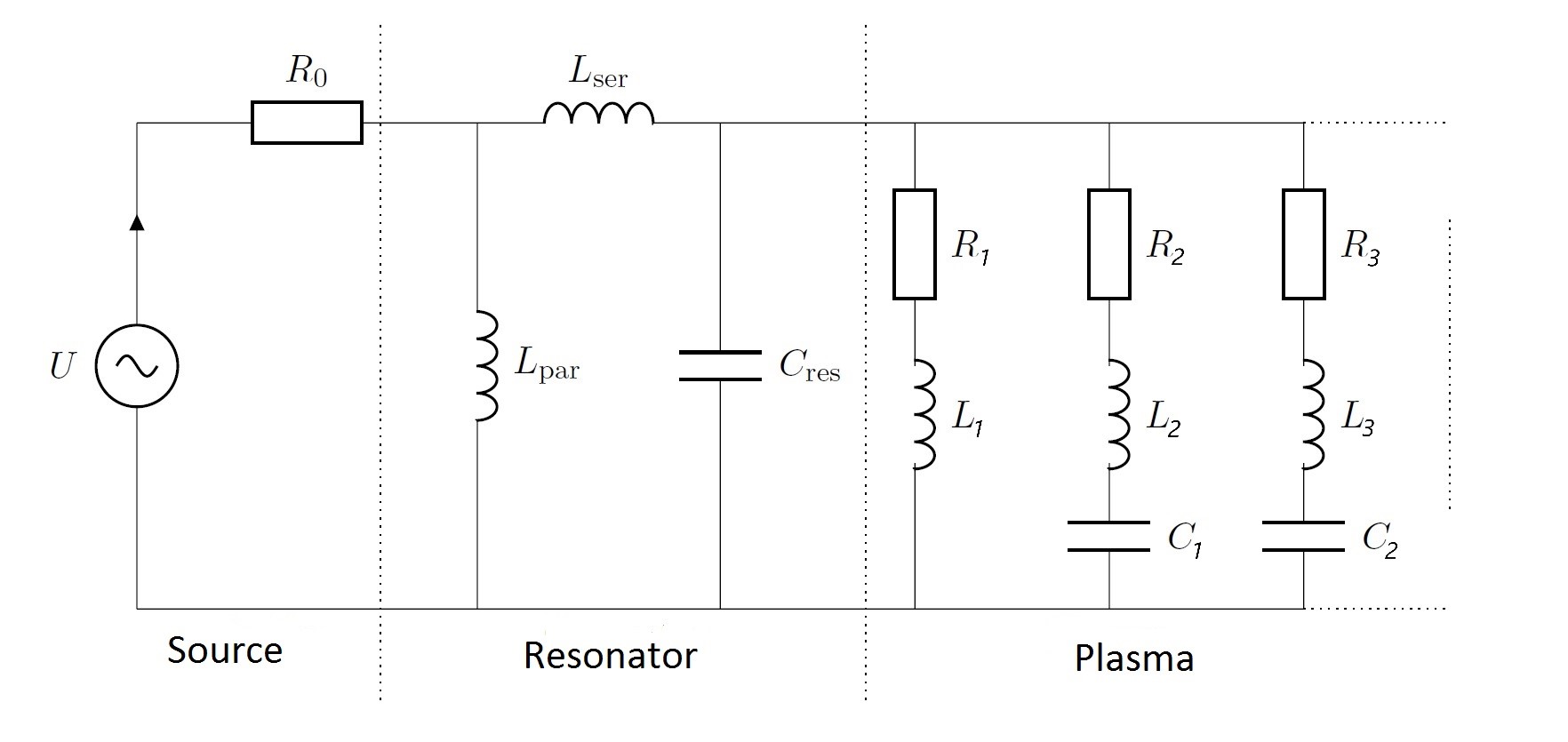
The resulting circuit diagram of the system is completed by the lumped element representation of the plasma itself (one inductive branch and an infinite number of capacitive branches) and shown in Fig. 2. The considered pressure is p=100Pap100Pa\textrm{p}=100\,\textrm{Pa}.

III Electromagnetic model (of a single Jet)

III.1 Ansatz

Cylindrical coordinates, (r,ϕ,z)𝑟italic-ϕ𝑧(r,\phi,z), are used for the calculation, where r𝑟r, ϕitalic-ϕ\phi and z𝑧z have their usual meanings. The z𝑧z-axis is centered in the middle of the cavity and the gap will be located at ϕ=0italic-ϕ0\phi=0. The dimensions of the resonator only allow the excitation of transversal-electric modes (TE-Mode) with a magnetic field pointing in z𝑧z-direction. Due to the gap there is no azimuthal symmetry and the transversal fields depend on r𝑟r as well as on ϕitalic-ϕ\phi. Consequently the magnetic field 𝐁𝐁\mathbf{B} and the electric field 𝐄𝐄\mathbf{E} can be written as follows, where n𝑛n is a zone index that takes the values p (plasma), s (sheath) and d (dielectric):

𝐁(n)superscript𝐁𝑛\displaystyle\mathbf{B}^{(n)} =Re(B¯z(n)(r,ϕ)eiωt𝐞z),absentResuperscriptsubscript¯𝐵𝑧𝑛𝑟italic-ϕsuperscripte𝑖𝜔𝑡subscript𝐞𝑧\displaystyle=\textrm{Re}(\underline{B}_{z}^{(n)}(r,\phi)\,\textrm{e}^{i\omega t}\,\mathbf{e}_{z}), (3)
𝐄(n)superscript𝐄𝑛\displaystyle\mathbf{E}^{(n)} =Re(E¯r(n)(r,ϕ)eiωt𝐞r+E¯ϕ(n)(r,ϕ)eiωt𝐞ϕ).absentResuperscriptsubscript¯𝐸𝑟𝑛𝑟italic-ϕsuperscripte𝑖𝜔𝑡subscript𝐞𝑟superscriptsubscript¯𝐸italic-ϕ𝑛𝑟italic-ϕsuperscripte𝑖𝜔𝑡subscript𝐞italic-ϕ\displaystyle=\textrm{Re}(\underline{E}_{r}^{(n)}(r,\phi)\,\textrm{e}^{i\omega t}\,\mathbf{e}_{r}+\underline{E}_{\phi}^{(n)}(r,\phi)\,\textrm{e}^{i\omega t}\,\mathbf{e}_{\phi}). (4)

In plasma, additionally, the charge density ρ𝜌\rho and the current density 𝐣𝐣\mathbf{j} have to be considered:

ρ𝜌\displaystyle\rho =Re(ρ¯(r,ϕ)eiωt),absentRe¯𝜌𝑟italic-ϕsuperscripte𝑖𝜔𝑡\displaystyle=\textrm{Re}(\underline{\rho}(r,\phi)\,\textrm{e}^{i\omega t}), (5)
𝐣𝐣\displaystyle\mathbf{j} =Re(j¯r(r,ϕ,t)eiωt𝐞r+j¯ϕ(r,ϕ)eiωt𝐞ϕ)absentResubscript¯𝑗𝑟𝑟italic-ϕ𝑡superscripte𝑖𝜔𝑡subscript𝐞𝑟subscript¯𝑗italic-ϕ𝑟italic-ϕsuperscripte𝑖𝜔𝑡subscript𝐞italic-ϕ\displaystyle=\textrm{Re}(\underline{j}_{r}(r,\phi,t)\,\textrm{e}^{i\omega t}\,\mathbf{e}_{r}+\underline{j}_{\phi}(r,\phi)\,\textrm{e}^{i\omega t}\,\mathbf{e}_{\phi}) (6)

The fields obey the full set of Maxwell equations, with electrical transport specifications for each of the zones. In the plasma, the equations are as follows, with vacuum permittivity ϵ0subscriptitalic-ϵ0\epsilon_{0}:

1μ01rB¯z(p)ϕ=j¯r+ϵ0iωE¯r(p),1subscript𝜇01𝑟superscriptsubscript¯𝐵𝑧pitalic-ϕsubscript¯𝑗𝑟subscriptitalic-ϵ0𝑖𝜔superscriptsubscript¯𝐸𝑟p\displaystyle\frac{1}{\mu_{0}}\frac{1}{r}\frac{\partial\underline{B}_{z}^{(\mathrm{p})}}{\partial\phi}=\underline{j}_{r}+\epsilon_{0}i\omega\underline{E}_{r}^{(\mathrm{p})}, (7)
1μ0B¯z(p)r=j¯ϕ+ϵ0iωE¯ϕ(p),1subscript𝜇0superscriptsubscript¯𝐵𝑧p𝑟subscript¯𝑗italic-ϕsubscriptitalic-ϵ0𝑖𝜔superscriptsubscript¯𝐸italic-ϕp\displaystyle-\frac{1}{\mu_{0}}\frac{\partial\underline{B}_{z}^{(\mathrm{p})}}{\partial r}=\underline{j}_{\phi}+\epsilon_{0}i\omega\underline{E}_{\phi}^{(\mathrm{p})}, (8)
1r(rE¯ϕ(p))r1rE¯r(p)ϕ=iωB¯z(p),1𝑟𝑟superscriptsubscript¯𝐸italic-ϕp𝑟1𝑟superscriptsubscript¯𝐸𝑟pitalic-ϕ𝑖𝜔superscriptsubscript¯𝐵𝑧p\displaystyle\frac{1}{r}\frac{\partial(r\underline{E}_{\phi}^{(\mathrm{p})})}{\partial r}-\frac{1}{r}\frac{\partial\underline{E}_{r}^{(\mathrm{p})}}{\partial\phi}=-i\omega\underline{B}_{z}^{(\mathrm{p})}, (9)
ϵ0r(rE¯r(p))r+ϵ0r(E¯ϕ(p))ϕ=ρ¯.subscriptitalic-ϵ0𝑟𝑟superscriptsubscript¯𝐸𝑟p𝑟subscriptitalic-ϵ0𝑟superscriptsubscript¯𝐸italic-ϕpitalic-ϕ¯𝜌\begin{split}\frac{\epsilon_{0}}{r}\frac{\partial(r\underline{E}_{r}^{(\mathrm{p})})}{\partial r}+\frac{\epsilon_{0}}{r}\frac{\partial(\underline{E}_{\phi}^{(\mathrm{p})})}{\partial\phi}&=\underline{\rho}.\\ \end{split} (10)

They are completed by the charge conservation equation,

iωρ¯+j¯rr+1rj¯ϕϕ=0,𝑖𝜔¯𝜌subscript¯𝑗𝑟𝑟1𝑟subscript¯𝑗italic-ϕitalic-ϕ0\displaystyle i\omega\underline{\rho}+\frac{\partial\underline{j}_{r}}{\partial r}+\frac{1}{r}\frac{\partial\underline{j}_{\phi}}{\partial\phi}=0, (11)

and the equation of motion in the transversal plane, according to the cold plasma model:

iωj¯r=ϵ0ωpe2E¯rνj¯r,𝑖𝜔subscript¯𝑗𝑟subscriptitalic-ϵ0superscriptsubscript𝜔pe2subscript¯𝐸𝑟𝜈subscript¯𝑗𝑟\displaystyle i\omega\underline{j}_{r}=\epsilon_{0}\omega_{\mathrm{pe}}^{2}\underline{E}_{r}-\nu\underline{j}_{r}, (12)
iωj¯ϕ=ϵ0ωpe2E¯ϕνj¯ϕ.𝑖𝜔subscript¯𝑗italic-ϕsubscriptitalic-ϵ0superscriptsubscript𝜔pe2subscript¯𝐸italic-ϕ𝜈subscript¯𝑗italic-ϕ\displaystyle i\omega\underline{j}_{\phi}=\epsilon_{0}\omega_{\mathrm{pe}}^{2}\underline{E}_{\phi}-\nu\underline{j}_{\phi}. (13)

Within the plasma sheath, the Maxwell equations take the following form:

1μ01rB¯z(s)ϕ=iωE¯r(s),1subscript𝜇01𝑟superscriptsubscript¯𝐵𝑧sitalic-ϕ𝑖𝜔superscriptsubscript¯𝐸𝑟s\displaystyle\frac{1}{\mu_{0}}\frac{1}{r}\frac{\partial\underline{B}_{z}^{(\mathrm{s})}}{\partial\phi}=i\omega\underline{E}_{r}^{(\mathrm{s})}, (15)
1μ0B¯z(s)r=ϵ0iωE¯ϕ(s),1subscript𝜇0superscriptsubscript¯𝐵𝑧s𝑟subscriptitalic-ϵ0𝑖𝜔superscriptsubscript¯𝐸italic-ϕs\displaystyle-\frac{1}{\mu_{0}}\frac{\partial\underline{B}_{z}^{(\mathrm{s})}}{\partial r}=\epsilon_{0}i\omega\underline{E}_{\phi}^{(\mathrm{s})}, (16)
1r(rE¯ϕ(s))r1rE¯r(s)ϕ=iωB¯z(s).1𝑟𝑟superscriptsubscript¯𝐸italic-ϕs𝑟1𝑟superscriptsubscript¯𝐸𝑟sitalic-ϕ𝑖𝜔superscriptsubscript¯𝐵𝑧s\displaystyle\frac{1}{r}\frac{\partial(r\underline{E}_{\phi}^{(\mathrm{s})})}{\partial r}-\frac{1}{r}\frac{\partial\underline{E}_{r}^{(\mathrm{s})}}{\partial\phi}=-i\omega\underline{B}_{z}^{(\mathrm{s})}. (17)
ϵ0r(rE¯r(s))r+ϵ0r(E¯ϕ(s))ϕ=0.subscriptitalic-ϵ0𝑟𝑟superscriptsubscript¯𝐸𝑟s𝑟subscriptitalic-ϵ0𝑟superscriptsubscript¯𝐸italic-ϕsitalic-ϕ0\begin{split}\frac{\epsilon_{0}}{r}\frac{\partial(r\underline{E}_{r}^{(\mathrm{s})})}{\partial r}+\frac{\epsilon_{0}}{r}\frac{\partial(\underline{E}_{\phi}^{(\mathrm{s})})}{\partial\phi}&=0.\\ \end{split} (18)

Within the dielectric, the equations are as follows, with permittivity ϵ=ϵ0ϵritalic-ϵsubscriptitalic-ϵ0subscriptitalic-ϵ𝑟\epsilon=\epsilon_{0}\epsilon_{r}:

1μ01rB¯z(d)ϕ=iωE¯r(d),1subscript𝜇01𝑟superscriptsubscript¯𝐵𝑧ditalic-ϕ𝑖𝜔superscriptsubscript¯𝐸𝑟d\displaystyle\frac{1}{\mu_{0}}\frac{1}{r}\frac{\partial\underline{B}_{z}^{(\mathrm{d})}}{\partial\phi}=i\omega\underline{E}_{r}^{(\mathrm{d})}, (19)
1μ0B¯z(d)r=ϵiωE¯ϕ(d),1subscript𝜇0superscriptsubscript¯𝐵𝑧d𝑟italic-ϵ𝑖𝜔superscriptsubscript¯𝐸italic-ϕd\displaystyle-\frac{1}{\mu_{0}}\frac{\partial\underline{B}_{z}^{(\mathrm{d})}}{\partial r}=\epsilon i\omega\underline{E}_{\phi}^{(\mathrm{d})}, (20)
1r(rE¯ϕ(d))r1rE¯r(d)ϕ=iωB¯z(d).1𝑟𝑟superscriptsubscript¯𝐸italic-ϕd𝑟1𝑟superscriptsubscript¯𝐸𝑟ditalic-ϕ𝑖𝜔superscriptsubscript¯𝐵𝑧d\displaystyle\frac{1}{r}\frac{\partial(r\underline{E}_{\phi}^{(\mathrm{d})})}{\partial r}-\frac{1}{r}\frac{\partial\underline{E}_{r}^{(\mathrm{d})}}{\partial\phi}=-i\omega\underline{B}_{z}^{(\mathrm{d})}. (21)
ϵr(rE¯r(d))r+ϵr(E¯ϕ(d))ϕ=0.italic-ϵ𝑟𝑟superscriptsubscript¯𝐸𝑟d𝑟italic-ϵ𝑟superscriptsubscript¯𝐸italic-ϕditalic-ϕ0\begin{split}\frac{\epsilon}{r}\frac{\partial(r\underline{E}_{r}^{(\mathrm{d})})}{\partial r}+\frac{\epsilon}{r}\frac{\partial(\underline{E}_{\phi}^{(\mathrm{d})})}{\partial\phi}&=0.\end{split} (22)

III.2 General solution

By using an expansion into a series ansatz, B¯z(n)(r,ϕ)superscriptsubscript¯𝐵𝑧𝑛𝑟italic-ϕ\underline{B}_{z}^{(n)}(r,\phi) can be rewritten as:

B¯z(n)(r,ϕ)subscriptsuperscript¯𝐵n𝑧𝑟italic-ϕ\displaystyle\underline{B}^{(\mathrm{n})}_{z}(r,\phi) =m=0(CmJm(rκ)+DmNm(rκ))cos(mϕ).absentsuperscriptsubscript𝑚0subscript𝐶𝑚subscript𝐽𝑚𝑟𝜅subscript𝐷𝑚subscript𝑁𝑚𝑟𝜅𝑚italic-ϕ\displaystyle=\sum_{m=0}^{\infty}\left(C_{m}J_{m}(r\kappa)+D_{m}N_{m}(r\kappa)\right)\cos(m\phi). (23)

Here Jm(rκ)subscript𝐽𝑚𝑟𝜅J_{m}(r\kappa) and Nm(rκ)subscript𝑁𝑚𝑟𝜅N_{m}(r\kappa) denote the Bessel functions of the first and the second kind and of order m𝑚m with corresponding constants Cmsubscript𝐶𝑚C_{m} and Dmsubscript𝐷𝑚D_{m}. The corresponding electric fields E¯r(n)(r,ϕ)subscriptsuperscript¯𝐸n𝑟𝑟italic-ϕ\underline{E}^{(\mathrm{n})}_{r}(r,\phi) and E¯ϕ(n)(r,ϕ)subscriptsuperscript¯𝐸nitalic-ϕ𝑟italic-ϕ\underline{E}^{(\mathrm{n})}_{\phi}(r,\phi) are derived from the Maxwell equations. For B¯z(p)(r,ϕ)superscriptsubscript¯𝐵𝑧𝑝𝑟italic-ϕ\underline{B}_{z}^{(p)}(r,\phi), E¯r(p)(r,ϕ)superscriptsubscript¯𝐸𝑟𝑝𝑟italic-ϕ\underline{E}_{r}^{(p)}(r,\phi) and E¯ϕ(p)(r,ϕ)superscriptsubscript¯𝐸italic-ϕ𝑝𝑟italic-ϕ\underline{E}_{\phi}^{(p)}(r,\phi) the constant Dmsubscript𝐷𝑚D_{m} is zero for all m, as Nm(rκ)subscript𝑁𝑚𝑟𝜅N_{m}(r\kappa) goes to infinity for r0𝑟0r\rightarrow 0.

III.3 Boundary conditions

The boundary conditions for the electric and magnetic field are considered one by one, beginning with the tangential component of the electric field, where 𝐧𝐧\mathbf{n} represents the normal vector of the boundary surface. At the boundary between plasma and sheath, as well as between sheath and dielectric, E¯ϕ(n)superscriptsubscript¯𝐸italic-ϕn\underline{E}_{\phi}^{(\mathrm{n})} is continuous:

E¯ϕ,(p)(Rdδ,ϕ)superscriptsubscript¯𝐸italic-ϕp𝑅𝑑𝛿italic-ϕ\displaystyle\underline{E}_{\phi,}^{(\mathrm{p})}(R-d-\delta,\phi) =E¯ϕ(s)(Rdδ,ϕ)absentsuperscriptsubscript¯𝐸italic-ϕs𝑅𝑑𝛿italic-ϕ\displaystyle=\underline{E}_{\phi}^{(\mathrm{s})}(R-d-\delta,\phi) (24)
E¯ϕ(s)(Rd,ϕ)superscriptsubscript¯𝐸italic-ϕs𝑅𝑑italic-ϕ\displaystyle\underline{E}_{\phi}^{(\mathrm{s})}(R-d,\phi) =E¯ϕ(d)(Rd,ϕ).absentsuperscriptsubscript¯𝐸italic-ϕd𝑅𝑑italic-ϕ\displaystyle=\underline{E}_{\phi}^{(\mathrm{d})}(R-d,\phi). (25)

There are no surface currents at the considered boundaries and no magnetization, thus 𝐁𝐁\mathbf{B} is also continuous:

B¯z(p)(Rdδ,ϕ)subscriptsuperscript¯𝐵p𝑧𝑅𝑑𝛿italic-ϕ\displaystyle\underline{B}^{(\mathrm{p})}_{z}(R-d-\delta,\phi) =B¯z(s)(Rdδ,ϕ)absentsubscriptsuperscript¯𝐵s𝑧𝑅𝑑𝛿italic-ϕ\displaystyle=\underline{B}^{(\mathrm{s})}_{z}(R-d-\delta,\phi) (26)
B¯z(s)(Rd,ϕ)subscriptsuperscript¯𝐵s𝑧𝑅𝑑italic-ϕ\displaystyle\underline{B}^{(\mathrm{s})}_{z}(R-d,\phi) =B¯z(d)(Rd,ϕ).absentsubscriptsuperscript¯𝐵d𝑧𝑅𝑑italic-ϕ\displaystyle=\underline{B}^{(\mathrm{d})}_{z}(R-d,\phi). (27)

For the normal component of the electric field, 𝐄𝐧𝐄𝐧\mathbf{E}\cdot\mathbf{n}, the following conditions apply:

ϵ0iωE¯r(s)(Rdδ,ϕ)subscriptitalic-ϵ0𝑖𝜔superscriptsubscript¯𝐸rs𝑅𝑑𝛿italic-ϕ\displaystyle\epsilon_{0}i\omega\underline{E}_{\textrm{r}}^{(\mathrm{s})}(R-d-\delta,\phi) =j¯r(r,ϕ)+ϵ0iωE¯r(p)(Rdδ,ϕ)absentsubscript¯𝑗r𝑟italic-ϕsubscriptitalic-ϵ0𝑖𝜔subscriptsuperscript¯𝐸pr𝑅𝑑𝛿italic-ϕ\displaystyle=\underline{j}_{\textrm{r}}(r,\phi)+\epsilon_{0}i\omega\underline{E}^{(\mathrm{p})}_{\textrm{r}}(R-d-\delta,\phi) (28)
ϵiωE¯r(d)(Rd,ϕ)italic-ϵ𝑖𝜔subscriptsuperscript¯𝐸d𝑟𝑅𝑑italic-ϕ\displaystyle\epsilon i\omega\underline{E}^{(\mathrm{d})}_{r}(R-d,\phi) =ϵ0iωE¯r(s)(Rd,ϕ).absentsubscriptitalic-ϵ0𝑖𝜔subscriptsuperscript¯𝐸s𝑟𝑅𝑑italic-ϕ\displaystyle=\epsilon_{0}i\omega\underline{E}^{(\mathrm{s})}_{r}(R-d,\phi). (29)

The boundary condition for E¯ϕ(d)superscriptsubscript¯𝐸italic-ϕd\underline{E}_{\phi}^{(\mathrm{d})} on the resonators wall requires special attention. For r=R𝑟𝑅r=R the field E¯(d)superscript¯𝐸d\underline{E}^{(\mathrm{d})} vanishes for all ϕitalic-ϕ\phi (idealized metal surface), except for |ϕ|<ds/2Ritalic-ϕsubscript𝑑s2𝑅\lvert\phi\rvert<d_{\textrm{s}}/2R (gap area). According to chapter 2, an electrostatic regime is assumed within the gap and E¯(d)superscript¯𝐸d\underline{E}^{(\mathrm{d})} can described by the field of a capacitor at that position. Therefore the boundary condition takes the following form, with gap size dssubscript𝑑sd_{\textrm{s}} and the voltage u𝑢u at the gap:

E¯ϕ(d)(R,ϕ)={0for |ϕ|arctan(ds/2R)ds/2Ru/dsfor |ϕ|<arctan(ds/2R)ds/2R.superscriptsubscript¯𝐸italic-ϕd𝑅italic-ϕcases0for italic-ϕsubscript𝑑s2𝑅subscript𝑑s2𝑅𝑢subscriptd𝑠for italic-ϕsubscript𝑑s2𝑅subscript𝑑s2𝑅\underline{E}_{\phi}^{(\mathrm{d})}(R,\phi)=\begin{cases}0&\text{for }\lvert\phi\rvert\geq\arctan(d_{\textrm{s}}/2R)\approx d_{\textrm{s}}/2R\\ u/\textrm{d}_{s}&\text{for }\lvert\phi\rvert<\arctan(d_{\textrm{s}}/2R)\approx d_{\textrm{s}}/2R.\end{cases}

This represents a periodic rectangle function, with period 2π2𝜋2\pi. It can be expanded into a Fourier series. By doing so, the boundary condition takes the following form:

E¯ϕ(R,ϕ)=udS2π+m=1cos(mϕ)2uRsin(mdS2R)dS2mπ.subscript¯𝐸italic-ϕ𝑅italic-ϕ𝑢subscript𝑑𝑆2𝜋superscriptsubscript𝑚1𝑚italic-ϕ2𝑢𝑅𝑚subscript𝑑S2𝑅superscriptsubscript𝑑S2𝑚𝜋\displaystyle\underline{E}_{\phi}(R,\phi)=\frac{u}{d_{S}2\pi}+\sum_{m=1}^{\infty}\cos(m\phi)\frac{2uR\sin(\frac{md_{\textrm{S}}}{2R})}{{d_{\textrm{S}}}^{2}m\pi}. (30)

Solving the equations (7)-(13) and taking the boundary conditions into account, it leads to the following fields for the plasma bulk region:

B¯z(p)(r,ϕ)subscriptsuperscript¯𝐵p𝑧𝑟italic-ϕ\displaystyle\underline{B}^{(\mathrm{p})}_{z}(r,\phi) =m=0CmJm(rκ)cos(mϕ)absentsuperscriptsubscript𝑚0subscript𝐶𝑚subscript𝐽𝑚𝑟𝜅𝑚italic-ϕ\displaystyle=\sum_{m=0}^{\infty}C_{m}J_{m}(r\kappa)\cos(m\phi) (31)
E¯r(p)(r,ϕ)subscriptsuperscript¯𝐸p𝑟𝑟italic-ϕ\displaystyle\underline{E}^{(\mathrm{p})}_{r}(r,\phi) =c2m(iν+ω)r(ϵrνω+iϵrω2+iωpe2)m=0CmJm(rκ)sin(mϕ)absentsuperscript𝑐2𝑚𝑖𝜈𝜔𝑟subscriptitalic-ϵ𝑟𝜈𝜔𝑖subscriptitalic-ϵ𝑟superscript𝜔2𝑖superscriptsubscript𝜔𝑝𝑒2superscriptsubscript𝑚0subscript𝐶𝑚subscript𝐽𝑚𝑟𝜅𝑚italic-ϕ\displaystyle=\frac{-c^{2}m(-i\nu+\omega)}{r(\epsilon_{r}\nu\omega+i\epsilon_{r}\omega^{2}+i\omega_{pe}^{2})}\sum_{m=0}^{\infty}C_{m}J_{m}(r\kappa)\sin(m\phi) (32)
E¯ϕ(p)(r,ϕ)subscriptsuperscript¯𝐸pitalic-ϕ𝑟italic-ϕ\displaystyle\underline{E}^{(\mathrm{p})}_{\phi}(r,\phi) =c2(ν+iω)ϵrω(iν+ω)ωpe2κ2m=0Cm(Jm1(rκ)Jm+1(rκ))cos(mϕ)absentsuperscript𝑐2𝜈𝑖𝜔subscriptitalic-ϵ𝑟𝜔𝑖𝜈𝜔superscriptsubscript𝜔𝑝𝑒2𝜅2superscriptsubscript𝑚0subscript𝐶𝑚subscript𝐽𝑚1𝑟𝜅subscript𝐽𝑚1𝑟𝜅𝑚italic-ϕ\displaystyle=\frac{c^{2}(\nu+i\omega)}{\epsilon_{r}\omega(-i\nu+\omega)-\omega_{pe}^{2}}\frac{\kappa}{2}\sum_{m=0}^{\infty}C_{m}(J_{m-1}(r\kappa)-J_{m+1}(r\kappa))\cos(m\phi) (33)
j¯r(r,ϕ)subscript¯𝑗𝑟𝑟italic-ϕ\displaystyle\underline{j}_{r}(r,\phi) =ϵ0ωpe2ν+iωE¯r(r,ϕ)absentsubscriptitalic-ϵ0superscriptsubscript𝜔𝑝𝑒2𝜈𝑖𝜔subscript¯𝐸𝑟𝑟italic-ϕ\displaystyle=\frac{\epsilon_{0}\omega_{pe}^{2}}{\nu+i\omega}\underline{E}_{r}(r,\phi) (34)
j¯ϕ(r,ϕ)subscript¯𝑗italic-ϕ𝑟italic-ϕ\displaystyle\underline{j}_{\phi}(r,\phi) =ϵ0ωpe2ν+iωE¯ϕ(r,ϕ).absentsubscriptitalic-ϵ0superscriptsubscript𝜔𝑝𝑒2𝜈𝑖𝜔subscript¯𝐸italic-ϕ𝑟italic-ϕ\displaystyle=\frac{\epsilon_{0}\omega_{pe}^{2}}{\nu+i\omega}\underline{E}_{\phi}(r,\phi). (35)

The relation between ω𝜔\omega and κ𝜅\kappa takes the following form:

κ2=ω(ω2iνωωpe2)c2(ωiν).superscript𝜅2𝜔superscript𝜔2𝑖𝜈𝜔superscriptsubscript𝜔𝑝𝑒2superscript𝑐2𝜔𝑖𝜈\displaystyle\kappa^{2}=-\frac{\omega(\omega^{2}-i\nu\omega-\omega_{pe}^{2})}{c^{2}(\omega-i\nu)}. (36)

As the Fourier coefficients are part of Cmsubscript𝐶𝑚C_{m} (which can be found in the appendix) the expressions for 𝐁¯(p)(r,ϕ)superscript¯𝐁p𝑟italic-ϕ\underline{\mathbf{B}}^{(\mathrm{p})}(r,\phi), 𝐄¯(p)(r,ϕ)superscript¯𝐄p𝑟italic-ϕ\underline{\mathbf{E}}^{(\mathrm{p})}(r,\phi) and 𝐣¯(r,ϕ)¯𝐣𝑟italic-ϕ\underline{\mathbf{j}}(r,\phi) consist of an infinite number of modes. The physical meaning of the individual modes is discussed later.

III.4 Sheath modulation

A constant sheath length of δ=5×10⁵m𝛿5superscript105m\delta=5\times 10^{-5}\,\textrm{m} is assumed. Based on a simple step model a typical length scale for the sheath modulation can be estimated by:

Δ=jeneωRF.Δ𝑗esubscript𝑛𝑒subscript𝜔RF\displaystyle\Delta=\frac{j}{\textrm{e}n_{e}\omega_{\textrm{RF}}}. (37)

Here j𝑗j represented the perpendicular component of the current that is flowing through the sheath. For the considered plasma density (ne1019m1subscript𝑛esuperscript1019superscriptm1n_{\textrm{e}}\approx 10^{19}\textrm{m}^{-1}) it is well justified to neglect ΔΔ\Delta as Δδ103much-less-thanΔ𝛿superscript103\frac{\Delta}{\delta}\ll 10^{-3}. Even for a considerably lower plasma density the sheath modulation is negligible.

III.5 Admittance and absorbed power

In the next step the current I𝐼I that is being fed into the resonator is calculated. It is proportional to the discontinuity of the magnetic field strength [𝐇×𝐧]Iproportional-todelimited-[]𝐇𝐧𝐼[\mathbf{H}\times\mathbf{n}]\propto I at the boundary between the resonator and the gap area. The current results from integrating the Maxwell-Ampère equation over an area F=l×2ϵF𝐹𝑙2subscriptitalic-ϵFF=l\times 2\epsilon_{\textrm{F}} with sides l=l2𝑙subscript𝑙2l=l_{2} and 2ϵF2subscriptitalic-ϵF2\epsilon_{\textrm{F}}. Here F𝐹F is a contour containing the edge between cylinder and the capacitor gap. As the surface normal of F𝐹F is aligned in 𝐞rsubscript𝐞𝑟-\mathbf{e}_{r} direction, I𝐼I will completely flow through F𝐹F and it follows:

F×𝐇¯d𝐟=F(iω𝐃¯+𝐣¯f)d𝐟=I¯subscript𝐹¯𝐇d𝐟subscript𝐹𝑖𝜔¯𝐃subscript¯𝐣fd𝐟¯𝐼\displaystyle\int_{F}\nabla\times\mathbf{\underline{H}}\,\textrm{d}\mathbf{f}=\int_{F}\left(i\omega\mathbf{\underline{D}}+\mathbf{\underline{j}}_{\textrm{f}}\right)\,\textrm{d}\mathbf{f}=\underline{I} (38)

Here 𝐃¯¯𝐃\mathbf{\underline{D}} represents the electric displacement field and 𝐣¯fsubscript¯𝐣f\mathbf{\underline{j}}_{\textrm{f}} represents the free current. Using Stoke’s theorem this can be written as an integral over the boundary of F𝐹F:

I¯=F𝐇¯d𝐬.¯𝐼subscriptcontour-integral𝐹¯𝐇d𝐬\displaystyle\underline{I}=\oint_{\partial F}\mathbf{\underline{H}}\,\textrm{d}\mathbf{s}. (39)

The integration path consists of four individual ways:

I¯=0lH¯z(R,ϕgap+ϵF/R)dz+ϕgapϵF/Rϕgap+ϵF/RH¯z(R,ϕ)dϕ¯𝐼superscriptsubscript0𝑙subscript¯𝐻z𝑅subscriptitalic-ϕgapsubscriptitalic-ϵF𝑅d𝑧superscriptsubscriptsubscriptitalic-ϕgapsubscriptitalic-ϵF𝑅subscriptitalic-ϕgapsubscriptitalic-ϵF𝑅subscript¯𝐻z𝑅italic-ϕditalic-ϕ\displaystyle\underline{I}=\int_{0}^{l}\underline{H}_{\textrm{z}}(R,\phi_{\textrm{gap}}+\epsilon_{\textrm{F}}/R)\,\textrm{d}z+\int_{\phi_{\textrm{gap}}-\epsilon_{\textrm{F}}/R}^{\phi_{\textrm{gap}}+\epsilon_{\textrm{F}}/R}\underline{H}_{\textrm{z}}(R,\phi)\,\textrm{d}\mathbf{\phi}
+l0H¯z(R,ϕgapϵF/R)dz+ϕgap+ϵF/RϕgapϵF/RH¯z(R,ϕ)dϕ.superscriptsubscript𝑙0subscript¯𝐻z𝑅subscriptitalic-ϕgapsubscriptitalic-ϵF𝑅d𝑧superscriptsubscriptsubscriptitalic-ϕgapsubscriptitalic-ϵF𝑅subscriptitalic-ϕgapsubscriptitalic-ϵF𝑅subscript¯𝐻z𝑅italic-ϕditalic-ϕ\displaystyle+\int_{l}^{0}\underline{H}_{\textrm{z}}(R,\phi_{\textrm{gap}}-\epsilon_{\textrm{F}}/R)\,\textrm{d}z+\int_{\phi_{\textrm{gap}}+\epsilon_{\textrm{F}}/R}^{\phi_{\textrm{gap}}-\epsilon_{\textrm{F}}/R}\underline{H}_{\textrm{z}}(R,\phi)\,\textrm{d}\mathbf{\phi}. (40)

In cylindrical coordinates (R,ϕgap)𝑅subscriptitalic-ϕgap(R,\phi_{\textrm{gap}}) represents the position of the edge where the inner surface of the cylindrical tube an the gap capacitor meet. Due to 𝐇¯𝐞ϕbottom¯𝐇subscript𝐞italic-ϕ\mathbf{\underline{H}}\bot\mathbf{e}_{\phi} only the first and third term of (III.5) contribute to the result:

I¯=H¯z(R,ϕgap+ϵF)H¯z(R,ϕgapϵF).¯𝐼subscript¯𝐻z𝑅subscriptitalic-ϕgapsubscriptitalic-ϵFsubscript¯𝐻z𝑅subscriptitalic-ϕgapsubscriptitalic-ϵF\displaystyle\underline{I}=\underline{H}_{\textrm{z}}(R,\phi_{\textrm{gap}}+\epsilon_{\textrm{F}})-\underline{H}_{\textrm{z}}(R,\phi_{\textrm{gap}}-\epsilon_{\textrm{F}}). (41)

The jump of the magnetic field strength is equal to 𝐁¯¯𝐁\mathbf{\underline{B}} at the capavitor edge. Thus:

H¯z(R,ϕgap+ϵF)H¯z(R,ϕgapϵF)=1μ0B¯z(R,ϕgap).subscript¯𝐻z𝑅subscriptitalic-ϕgapsubscriptitalic-ϵFsubscript¯𝐻z𝑅subscriptitalic-ϕgapsubscriptitalic-ϵF1subscript𝜇0subscript¯𝐵z𝑅subscriptitalic-ϕgap\displaystyle\underline{H}_{\textrm{z}}(R,\phi_{\textrm{gap}}+\epsilon_{\textrm{F}})-\underline{H}_{\textrm{z}}(R,\phi_{\textrm{gap}}-\epsilon_{\textrm{F}})=\frac{1}{\mu_{0}}\underline{B}_{\textrm{z}}(R,\phi_{\textrm{gap}}). (42)

Finally an expression for the plasma admittance YPsubscript𝑌PY_{\textrm{P}} can be gained:

YP=Iu=1ulμ0B¯z(R,ϕgap).subscript𝑌P𝐼𝑢1𝑢𝑙subscript𝜇0subscript¯𝐵z𝑅subscriptitalic-ϕgap\displaystyle Y_{\textrm{P}}=\frac{I}{u}=\frac{1}{u}\frac{l}{\mu_{0}}\underline{B}_{\textrm{z}}(R,\phi_{\textrm{gap}}). (43)

The admittance is expressed as a function of nesubscript𝑛en_{\textrm{e}} and ω𝜔\omega, as κ𝜅\kappa is a function of ω𝜔\omega and ωpesubscript𝜔pe\omega_{\textrm{pe}} (apparent from equation (36)) and ωpe=nee2/ϵ0mesubscript𝜔pesubscript𝑛esuperscript𝑒2subscriptitalic-ϵ0subscript𝑚e\omega_{\textrm{pe}}=\sqrt{n_{\textrm{e}}e^{2}/\epsilon_{0}m_{\textrm{e}}}. In addition YPsubscript𝑌PY_{\textrm{P}} consists of an infinite number of modes as it includes the expression of 𝐁𝐁\mathbf{B}:

YP(ω,ne)=m=0Ym(ω,ne).subscript𝑌P𝜔subscript𝑛𝑒superscriptsubscript𝑚0subscript𝑌𝑚𝜔subscript𝑛e\displaystyle Y_{\textrm{P}}(\omega,n_{e})=\sum_{m=0}^{\infty}Y_{m}(\omega,n_{\textrm{e}}). (44)

The admittance of the plasma from equation (44) is used to evaluate eq. (2). The resulting expression of YS(ω,ne)subscript𝑌S𝜔subscript𝑛eY_{\textrm{S}}(\omega,n_{\textrm{e}}) contains fundamental information of the combined system of plasma and resonator and its frequency dependent behavior. It can be related to the lumped element model presented in Fig 2. The individual modes of the plasma admittance YP,m(ω,ne)subscript𝑌P𝑚𝜔subscript𝑛eY_{\textrm{P},m}(\omega,n_{\textrm{e}}) can be identified with different branches in the parallel circuit on the right in Fig 2 and different discharge regimes. This is discussed in more detail later. The real part of YS(ω,ne)subscript𝑌S𝜔subscript𝑛eY_{\textrm{S}}(\omega,n_{\textrm{e}}) is shown in Fig 5. For a given microwave source with amplitude uSsubscript𝑢Su_{\textrm{S}} the power dissipated in the plasma finally takes the form:

Pabs(ω,ne)subscript𝑃abs𝜔subscript𝑛e\displaystyle P_{\textrm{abs}}(\omega,n_{\textrm{e}}) =12|uS|2Re(YS(ω,ne))absent12superscriptsubscript𝑢S2Resubscript𝑌S𝜔subscript𝑛e\displaystyle=\frac{1}{2}|u_{\textrm{S}}|^{2}\operatorname{Re}(Y_{\textrm{S}}(\omega,n_{\textrm{e}})) (45)

IV Plasma model

In this section global balance equations is used to describe certain plasma parameters. The term ”global” refers to a volume averaged description. This kind of model is commonly employed to predict spatially averaged parameters if the spatial information is not of interest ref13 . The global model is based on a particle balance and a power balance equation. At first the particle balance is considered. In the steady state regime the number of electrons Nesubscript𝑁eN_{\textrm{e}} is constant. Thus, the number of electrons gained is in balance with the number of electrons lost:

dNedt=Kiz(Te)Ne1τlossNe=0.dsubscript𝑁ed𝑡subscript𝐾izsubscript𝑇esubscript𝑁e1subscript𝜏losssubscript𝑁e0\displaystyle\frac{\textrm{d}N_{\textrm{e}}}{\textrm{d}t}=K_{\textrm{iz}}(T_{\textrm{e}})N_{\textrm{e}}-\frac{1}{\tau_{\textrm{loss}}}N_{\textrm{e}}=0. (47)

Here Kizsubscript𝐾izK_{\textrm{iz}} represents the rate coefficient for ionization as a function of the electron-temperature Tesubscript𝑇eT_{\textrm{e}}, and τlosssubscript𝜏loss\tau_{\textrm{loss}} is an effective time constant that describes the decay processes. Depending on the plasma parameters various ionization processes play a role (direct ionization, ionization through various exited states). The corresponding rate coefficients are to be selected accordingly. As the number of electrons is time independent, equation (47) can be used for the determination of Tesubscript𝑇eT_{\textrm{e}}. Secondly, the power balance is considered, with the absorbed power, Pabssubscript𝑃absP_{\textrm{{abs}}}, being equal to the power lost:

ddt(32neTe)=PabsK(Te)ϵNe=0.dd𝑡32subscript𝑛esubscript𝑇esubscript𝑃abssuperscript𝐾subscript𝑇esuperscriptitalic-ϵsubscript𝑁e0\displaystyle\frac{\textrm{d}}{\textrm{d}t}\left(\frac{3}{2}n_{\textrm{e}}T_{\textrm{e}}\right)=P_{\textrm{abs}}-K^{*}(T_{\textrm{e}})\epsilon^{*}N_{\textrm{e}}=0. (48)

Where generally K(Te)superscript𝐾subscript𝑇eK^{*}(T_{\textrm{e}}) is a rate coefficient and ϵsuperscriptitalic-ϵ\epsilon^{*} the corresponding energy. Following the considerations above, a power loss model for an argon plasma is being developed. The total power loss Ploss(ne)subscript𝑃losssubscript𝑛𝑒P_{\textrm{loss}}(n_{e}) is finally a function of nesubscript𝑛𝑒n_{e}. In order to determine Plosssubscript𝑃lossP_{\textrm{loss}} more precisely, the flux of particles with respect to the boundary surfaces is considered in cylindrical coordinates. For radial losses the surface of the cylinder wall AM=2πRlsubscript𝐴M2𝜋𝑅𝑙A_{\textrm{M}}=2\pi Rl represents the boundary surface. The question arises if the axial losses can be treated in a similar way. Since the considered plasma operates as a jet, there are no axial walls and plasma processes are not strongly limited to the extension of the resonator block. Therefore, it is expected that the radial losses are dominant in comparison to the axial losses. We neglect the axial losses and assume a constant density profile along the z-axis as the plasma jet extends much beyond the resonator length. Under this assumption the considered wall flux of particles ΨwsubscriptΨ𝑤\Psi_{w} takes the form:

Ψw=vBn0AMh.subscriptΨwsubscript𝑣Bsubscript𝑛0subscript𝐴M\displaystyle\Psi_{\textrm{w}}=v_{\textrm{B}}n_{0}A_{\textrm{M}}h. (49)

Here vBsubscript𝑣Bv_{\textrm{B}} denotes the Bohm velocity. Further on n0subscript𝑛0n_{0} denotes the electron density short of the sheath. The so called hh-factor is introduced in order to express the wall flux ΨwsubscriptΨ𝑤\Psi_{w} as a function of the average electron density nesubscript𝑛𝑒n_{e} ref14 . For this simplified model, the considered geometry and a reference pressure of 100Pa100Pa100\,\textrm{Pa} the following hh-factor is used ref10 .

h=0.80(4+Rλi)1/2.0.80superscript4𝑅subscript𝜆i12\displaystyle h=0.80\left(4+\frac{R}{\lambda_{\textrm{i}}}\right)^{-1/2}. (50)

Here λisubscript𝜆i\lambda_{\textrm{i}} denotes the mean free path for ions. For further calculations the collisional energy loss per electron-ion pair created, εcsubscript𝜀c\varepsilon_{\textrm{c}}, is considered. It is defined by ref10 :

Kcεc=Kizεiz+Kexεex+Kel3mMTe.subscript𝐾csubscript𝜀csubscript𝐾izsubscript𝜀izsubscript𝐾exsubscript𝜀exsubscript𝐾el3𝑚𝑀subscript𝑇e\displaystyle K_{\textrm{c}}\varepsilon_{\textrm{c}}=K_{\textrm{iz}}\varepsilon_{\textrm{iz}}+K_{\textrm{ex}}\varepsilon_{\textrm{ex}}+K_{\textrm{el}}\frac{3m}{M}T_{\textrm{e}}. (51)

In this equation the loss of electron energy due to ionization, εizsubscript𝜀iz\varepsilon_{\textrm{iz}}, excitation, εexsubscript𝜀ex\varepsilon_{\textrm{ex}}, and the mean energy for elastic scattering (with neutrals), 3mMTe3𝑚𝑀subscript𝑇e\frac{3m}{M}T_{\textrm{e}}, is taken into account. Stepwise ionization is neglected as the quantitative difference to direct ionization is less than 20%, according to the model of Kemaneci et al., ref15 . Here Kizsubscript𝐾izK_{\textrm{iz}}, Kexsubscript𝐾exK_{\textrm{ex}} and Kelsubscript𝐾elK_{\textrm{el}} represent the corresponding rate coefficients, while m𝑚m is the electron mass and M𝑀M the neutral particle mass. The values of these rate coefficients are Kiz=2.34×10¹⁴Te0.59e17.44/Tem3/ssubscript𝐾iz2.34superscript1014superscriptsubscriptTe0.59superscripte17.44subscriptTesuperscriptm3𝑠K_{\textrm{iz}}=2.34\times 10^{-14}\textrm{T}_{\textrm{e}}^{0.59}\textrm{e}^{-17.44/\textrm{T}_{\textrm{e}}}\,\textrm{m}^{3}/s, Kex=2.48×10¹⁴Te0.33e12.78/Tem3/ssubscript𝐾ex2.48superscript1014superscriptsubscriptTe0.33superscripte12.78subscriptTesuperscriptm3𝑠K_{\textrm{ex}}=2.48\times 10^{-14}\textrm{T}_{\textrm{e}}^{0.33}\textrm{e}^{-12.78/\textrm{T}_{\textrm{e}}}\,\textrm{m}^{3}/s and Kel=2.336×10¹⁴Te1.609e0.0618ln(Te)20.1171ln(Te)3m3/sK_{\textrm{el}}=2.336\times 10^{-14}\textrm{T}_{\textrm{e}}^{1.609}\textrm{e}^{0.0618\ln(\textrm{T}_{\textrm{e}})^{2}-0.1171\ln(\textrm{T}_{\textrm{e}})^{3}}\,\textrm{m}^{3}/s, according to [15]-[16]. For argon εiz=15.76eVsubscript𝜀iz15.76eV\varepsilon_{\textrm{iz}}=15.76\,\textrm{eV} and εex=12.14eVsubscript𝜀ex12.14eV\varepsilon_{\textrm{ex}}=12.14\,\textrm{eV} [10]. In addition, the energy loss for ions, eVsh𝑒subscript𝑉sheV_{\textrm{sh}}, and the average kinetic energy carried out by lost electrons, 2Te2subscript𝑇e2T_{\textrm{e}}, is to be accounted. The sheath-voltage Vshsubscript𝑉shV_{\textrm{sh}} represents the potential difference caused by the unequal charge distribution in the sheath. The elementary charge is denoted with e𝑒e. In summary the total energy loss Elosssubscript𝐸lossE_{\textrm{loss}} per electron-ion pair created is given by:

Eloss=εiz+KexKizεex+KelKiz3mMTe+eVsh+2Te.subscript𝐸losssubscript𝜀izsubscript𝐾exsubscript𝐾izsubscript𝜀exsubscript𝐾elsubscript𝐾iz3𝑚𝑀subscript𝑇e𝑒subscript𝑉sh2subscript𝑇e\displaystyle E_{\textrm{loss}}=\varepsilon_{\textrm{iz}}+\frac{K_{\textrm{ex}}}{K_{\textrm{iz}}}\varepsilon_{\textrm{ex}}+\frac{K_{\textrm{el}}}{K_{\textrm{iz}}}\frac{3m}{M}T_{\textrm{e}}+eV_{\textrm{sh}}+2T_{\textrm{e}}. (52)

Multiplication of eq. (52) with the flux of particles ψwsubscript𝜓w\psi_{\textrm{w}} leads to an expression for the total loss power:

Ploss(ne)=nevBAMh(εiz+KexKizεex+KelKiz3mMTe+eVsh+2Te).subscript𝑃losssubscript𝑛esubscript𝑛esubscript𝑣Bsubscript𝐴Msubscript𝜀izsubscript𝐾exsubscript𝐾izsubscript𝜀exsubscript𝐾elsubscript𝐾iz3𝑚𝑀subscript𝑇e𝑒subscript𝑉sh2subscript𝑇e\displaystyle P_{\textrm{loss}}(n_{\textrm{e}})=n_{\textrm{e}}v_{\textrm{B}}A_{\textrm{M}}h\left(\varepsilon_{\textrm{iz}}+\frac{K_{\textrm{ex}}}{K_{\textrm{iz}}}\varepsilon_{\textrm{ex}}+\frac{K_{\textrm{el}}}{K_{\textrm{iz}}}\frac{3m}{M}T_{\textrm{e}}+eV_{\textrm{sh}}+2T_{\textrm{e}}\right). (53)

Using the presented coefficients for argon, equations (47) gives an electron temperature of Te=2.5eVsubscript𝑇e2.5eVT_{\textrm{e}}=2.5\,\textrm{eV}.

V Characteristics of the system

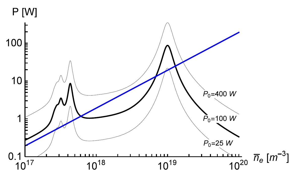
In this section fundamental insights into the characteristics of the system will be gained. To investigate the power balance Plosssubscript𝑃lossP_{\textrm{loss}} and Pabssubscript𝑃absP_{\textrm{abs}} are plotted as functions of nesubscript𝑛en_{\textrm{e}}. The resulting plot is shown in Fig 4. Intersections of both curves represent operating points and meet the condition:

Pabs(ne)=Ploss(ne).subscript𝑃abssubscript𝑛esubscript𝑃losssubscript𝑛e\displaystyle P_{\textrm{{abs}}}(n_{\textrm{e}})=P_{\textrm{loss}}(n_{\textrm{e}}). (54)

It is assumed that an operating point can be characterized as stable if the following criterion is met:

Pabsne<Plossne.subscript𝑃abssubscript𝑛𝑒subscript𝑃losssubscript𝑛𝑒\displaystyle\frac{\partial P_{\textrm{abs}}}{\partial n_{e}}<\frac{\partial P_{\textrm{loss}}}{\partial n_{e}}. (55)

According to Fig 4 the absorbed power Pabssubscript𝑃absP_{\textrm{abs}} shows a nonlinear behavior as a function of nesubscript𝑛en_{\textrm{e}} resulting in multiple solutions of equation 54. Thus, a hysteresis is expected to occur with the variation of the plasma parameters and input power. The set

{(ne,P)|P:=Pabs(ne)=!Ploss(ne)}\displaystyle\left\{(n_{\textrm{e}},P)\,\lvert\,P:=P_{\textrm{abs}}(n_{\textrm{e}})\overset{!}{=}P_{\textrm{loss}}(n_{\textrm{e}})\right\} (56)

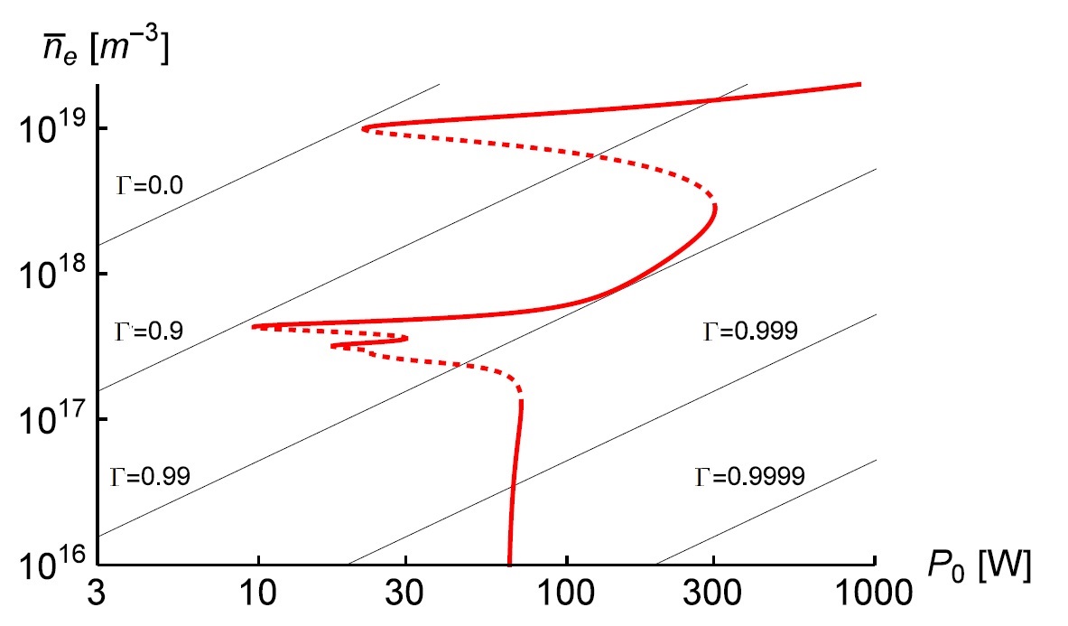
represents all possible combinations of nesubscript𝑛en_{\textrm{e}} and P𝑃P for operation in power balance. In Fig 6 the result is shown graphically. Stable and unstable operating points are marked differently. In addition, the real value of the reflection coefficient |Γ|Γ\lvert\Gamma\rvert is plotted in figure 6, with:

Γ=ZSZ0ZS+Z0.Γsubscript𝑍Ssubscript𝑍0subscript𝑍Ssubscript𝑍0\displaystyle\Gamma=\frac{Z_{\textrm{S}}-Z_{0}}{Z_{\textrm{S}}+Z_{0}}. (57)

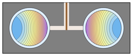
The impedance of the combined system of plasma and resonator is given by ZS=YS(ω,ne)1subscript𝑍Ssubscript𝑌Ssuperscript𝜔subscript𝑛e1Z_{\textrm{S}}=Y_{\textrm{S}}(\omega,n_{\textrm{e}})^{-1}. Finally the pattern of the field lines is plotted for two characteristic values of the electron density (ne1017m3subscript𝑛esuperscript1017superscriptm3n_{\textrm{e}}\approx 10^{17}\textrm{m}^{-3} and ne1019m3subscript𝑛esuperscript1019superscriptm3n_{\textrm{e}}\approx 10^{19}\textrm{m}^{-3}). The resulting plots are shown in Figs 7 and 8.

In conclusion the following insights can be gained:

  • Two clearly separated operating regimes can be identified. One regime is located at a value of ne1017m3subscript𝑛esuperscript1017superscriptm3n_{\textrm{e}}\approx 10^{17}\textrm{m}^{-3} and the second regime is located at a value of ne1019m3subscript𝑛esuperscript1019superscriptm3n_{\textrm{e}}\approx 10^{19}\textrm{m}^{-3}.

  • The mode Y0(ω,ne)subscript𝑌0𝜔subscript𝑛eY_{0}(\omega,n_{\textrm{e}}) constitutes the dominant contribution in the second (high nesubscript𝑛en_{\textrm{e}}) regime, while Y1(ω,ne)subscript𝑌1𝜔subscript𝑛eY_{1}(\omega,n_{\textrm{e}}) and higher modes dominate the first (low nesubscript𝑛en_{\textrm{e}}) regime (as resulted from Fig 4).

  • For the low nesubscript𝑛en_{\textrm{e}} case the field line patterns are similar to a field of a capacitor and it can be assumed the energy is mainly capacitively coupled to the system. For the high nesubscript𝑛en_{\textrm{e}} case circular currents are present and a mainly inductively coupled energy transfer can be assumed.

  • The low nesubscript𝑛en_{\textrm{e}} mode requires a minimum of P0=10Wsubscript𝑃010WP_{0}=10\,\textrm{W} and appears to be relatively poor in terms of efficiency (|Γ|0.9)Γ0.9(\left|\Gamma\right|\approx 0.9). The high nesubscript𝑛en_{\textrm{e}} mode requires a minimum of P0=25Wsubscript𝑃025WP_{0}=25\,\textrm{W} and gives a significantly higher efficiency (|Γ|0.1)Γ0.1(\left|\Gamma\right|\approx 0.1).

  • Hysteresis occurs when cycling between the two discharge regimes.

Consequently the high nesubscript𝑛en_{\textrm{e}} mode is called inductive mode or H-mode and corresponds to the inductive branch (m=0𝑚0m=0) in the lumped element model in Fig 2. The low nesubscript𝑛en_{\textrm{e}} mode is called capacitive mode or E-mode and corresponds to the capacitive branch (m=1𝑚1m=1) in the lumped element model in Fig 2. Modes of higher order provide a far less important contribution. Particularly, during H-mode operation they can be neglected.

First experimental results have been gathered with the MMWICP ref11 -ref12 . The predicted behavior is in good agreement with the experimental results concerning fundamental aspects of the system. This regards particularly the existence of multiple modes, different discharge regimes and the values of nesubscript𝑛en_{\textrm{e}} as well as the predicted 2D pattern of field lines (the H-mode is optically proven for the MMICP and a nitrogen discharge [11]). A quantitative comparison to experimental results will be subject to further research when a global model for nitrogen and additional diagnostics are available.

VI Summary and conclusion

In this paper a Miniature Microwave ICP plasma jet (MMWICP) is theoretically investigated. An electromagnetic model for the absorbed power is delivered based on fundamental field equations. This leads to a Fourier series representation of the electromagnetic fields with an infinite number of modes ordered by the azimuthal wave number m. In addition a global model for the power loss is derived. By equating both calculated powers, Pabs=Plosssubscript𝑃abssubscript𝑃lossP_{\textrm{abs}}=P_{\textrm{loss}}, it is possible to identify stable operating points. With respect to the electron density, two clearly separated discharge regimes are identified. The corresponding field lines patterns are plotted. The results are used to determine the physical meaning of the discharge regimes. The high electron density regime requires ne1019m3subscript𝑛esuperscript1019superscriptm3n_{\textrm{e}}\approx 10^{19}\,\textrm{m}^{-3} and represents inductive coupling. It is identified as H-mode. In this case strong circular currents are present and the mode m=0𝑚0m=0 is dominating. The low electron density regime requires ne51017m3subscript𝑛e5superscript1017superscriptm3n_{\textrm{e}}\approx 5\cdot 10^{17}\,\textrm{m}^{-3} and represents capacitive coupling. Consequently it is identified as E-mode. In this case the field line pattern are similar to a capacitor and the mode m=1𝑚1m=1 is dominating. Due to the nonlinear behavior of Pabssubscript𝑃absP_{\textrm{abs}}, the equation Pabs=Plosssubscript𝑃abssubscript𝑃lossP_{\textrm{abs}}=P_{\textrm{loss}} has multiple solutions. Therefore hysteresis effects appear at different points, when cycling between E- and H-mode. The efficiency is also depending on the discharge regimes. During E-mode operation the efficiency ist low: (|Γ|0.9)Γ0.9(\left|\Gamma\right|\approx 0.9). Only a low degree of the power is transported into the plasma. In contrast to that operation in E-mode provides high efficiency and low reflection: (|Γ|0.09)Γ0.09(\left|\Gamma\right|\approx 0.09). A comparison to existing experiments is limited to the electromagnetic aspects as experimental results are only available for nitrogen. A quantitative comparison to experimental results will be subject to further research when a global model for nitrogen and additional diagnostics are available. In conclusion the feasibility of inductive power coupling for the MMWICP resonator is shown and its electromagnetic characteristics are examined and presented.

VII Acknowledgements

The authors gratefully acknowledge support by Deutsche Forschungsgemeinschaft DFG via the project 389090373.

Appendix

The constant Cmsubscript𝐶𝑚C_{m} results from solving equations (7)-(13). It contains the Fourier coefficients and takes the following form:

Cm=4c4Rωϵr(iνωω2+ωpe2)Ym(C1)Ym(C2)×({udS2πfor m=02uRsin(mdS2R)dS2mπfor m1)(π2(icω(d+δR)(iνωω2+ωpe)2Jm((dR+δ)κ)×Jm1(C1)Ym(C1)Jm(C1)Ym1(C1)Jm(C2)Ym1(C2)Jm1(C2)Ym(C2)(c(RωϵrYm1(C3)cmYm(C3))Jm(C2)+c(cmJm(C3)RωϵrJm1(C3))Ym(C2))×(cωϵr(Rd)Ym(C4)Ym1(C2)+c(cm(ϵr1)Ym(C4)+ωϵr(dR)Ym1(C4))Ym(C2)))+c(cω(ν+iω)(κ(d+δR)Jm1((dR+δ)κ)+mJm((dR+δ)κ))Ym(C1)+i(iνωω2+ωpe)2Jm((dR+δ)κ)[ω(d+δR)Ym1(C1)+cmYm(C1)](Jm(C5)(c2ωϵr(dR)Ym(C4)))×(cmYm(C3)RωϵrYm1(C3))Jm(C2)Ym1(C2)Jm1(C2)Ym(C2)(c(RωϵrYm1(C3)cmYm(C3))Jm(C2)+c(cmJm(C3)RωϵrJm1(C3))Ym(C2))×(cωϵr(Rd)Ym(C4)Ym1(C2)+c(cm(ϵr1)Ym(C4)+ωϵr(dR)Ym1(C4))Ym(C2)))×Ym(C5)(c2ωϵr(dR)Jm(C4)(cmYm(C3)RωϵrYm1(C3))Jm(C2)Ym1(C2)Jm1(C2)Ym(C2)+(c(RωϵrYm1(C3)cmYm(C3))Jm(C2)+c(cmJm(C3)RωϵrJm1(C3))Ym(C2))C_{m}=4c^{4}R\omega\epsilon_{\textrm{r}}\left(i\nu\omega-\omega^{2}+\omega_{\textrm{pe}}^{2}\right)Y_{m}\left(C_{1}\right)Y_{m}\left(C_{2}\right)\\ \times\left(\begin{cases}\frac{u}{d_{S}2\pi}&\text{for }m=0\\ \frac{2uR\sin(\frac{md_{\textrm{S}}}{2R})}{{d_{\textrm{S}}}^{2}m\pi}&\text{for }m\geq 1\end{cases}\right)\left(\pi^{2}\left(ic\omega(d+\delta-R)\left(i\nu\omega-\omega^{2}+\omega_{\textrm{pe}}{}^{2}\right)J_{m}(-(d-R+\delta)\kappa)\right.\right.\\ \times J_{m-1}\left(C_{1}\right)Y_{m}\left(C_{1}\right)-J_{m}\left(C_{1}\right)Y_{m-1}\left(C_{1}\right)J_{m}\left(C_{2}\right)Y_{m-1}\left(C_{2}\right)-J_{m-1}\left(C_{2}\right)Y_{m}\left(C_{2}\right)\\ -\left(c\left(R\omega\sqrt{\epsilon_{\textrm{r}}}Y_{m-1}\left(C_{3}\right)-cmY_{m}\left(C_{3}\right)\right)J_{m}\left(C_{2}\right)\right.+\left.c\left(cmJ_{m}\left(C_{3}\right)-R\omega\sqrt{\epsilon_{\textrm{r}}}J_{m-1}\left(C_{3}\right)\right)Y_{m}\left(C_{2}\right)\right)\\ \times\left(c\omega\sqrt{\epsilon_{\textrm{r}}}(R-d)Y_{m}\left(C_{4}\right)Y_{m-1}\left(C_{2}\right)\right.+\left.\left.c\left(cm(\epsilon_{\textrm{r}}-1)Y_{m}\left(C_{4}\right)+\omega\epsilon_{\textrm{r}}(d-R)Y_{m-1}\left(C_{4}\right)\right)Y_{m}\left(C_{2}\right)\right)\right)\\ +c\left(c\omega(\nu+i\omega)(\kappa(d+\delta-R)J_{m-1}(-(d-R+\delta)\kappa)+mJ_{m}(-(d-R+\delta)\kappa))Y_{m}\left(C_{1}\right)\right.\\ +i\left(i\nu\omega-\omega^{2}+\omega_{\textrm{pe}}{}^{2}\right)J_{m}(-(d-R+\delta)\kappa)[\omega(d+\delta-R)Y_{m-1}\left(C_{1}\right)+cmY_{m}\left(C_{1}\right)]\left(J_{m}\left(C_{5}\right)\left(c^{2}\omega\sqrt{\epsilon_{\textrm{r}}}(d-R)Y_{m}\left(C_{4}\right)\right)\right)\\ \times\left(cmY_{m}\left(C_{3}\right)-R\omega\sqrt{\epsilon_{\textrm{r}}}Y_{m-1}\left(C_{3}\right)\right)J_{m}\left(C_{2}\right)Y_{m-1}\left(C_{2}\right)-J_{m-1}\left(C_{2}\right)Y_{m}\left(C_{2}\right)\\ -\left(c\left(R\omega\sqrt{\epsilon_{\textrm{r}}}Y_{m-1}\left(C_{3}\right)-cmY_{m}\left(C_{3}\right)\right)J_{m}\left(C_{2}\right)\right.+\left.c\left(cmJ_{m}\left(C_{3}\right)-R\omega\sqrt{\epsilon_{\textrm{r}}}J_{m-1}\left(C_{3}\right)\right)Y_{m}\left(C_{2}\right)\right)\\ \times\left(c\omega\sqrt{\epsilon_{\textrm{r}}}(R-d)Y_{m}\left(C_{4}\right)Y_{m-1}\left(C_{2}\right)\right.+\left.\left.c\left(cm(\epsilon_{\textrm{r}}-1)Y_{m}\left(C_{4}\right)+\omega\epsilon_{\textrm{r}}(d-R)Y_{m-1}\left(C_{4}\right)\right)Y_{m}\left(C_{2}\right)\right)\right)\\ \times Y_{m}\left(C_{5}\right)\left(-c^{2}\omega\sqrt{\epsilon_{\textrm{r}}}(d-R)J_{m}\left(C_{4}\right)\left(cmY_{m}\left(C_{3}\right)-R\omega\sqrt{\epsilon_{\textrm{r}}}Y_{m-1}\left(C_{3}\right)\right)\right.J_{m}\left(C_{2}\right)Y_{m-1}\left(C_{2}\right)-J_{m-1}\left(C_{2}\right)Y_{m}\left(C_{2}\right)\\ +\left(c\left(R\omega\sqrt{\epsilon_{\textrm{r}}}Y_{m-1}\left(C_{3}\right)-cmY_{m}\left(C_{3}\right)\right)J_{m}\left(C_{2}\right)\right.+\left.c\left(cmJ_{m}\left(C_{3}\right)-R\omega\sqrt{\epsilon_{\textrm{r}}}J_{m-1}\left(C_{3}\right)\right)Y_{m}\left(C_{2}\right)\right)\\

The meaning of the following abbreviations applies:

C1subscript𝐶1\displaystyle C_{1} =(dR+δ)ωcabsent𝑑𝑅𝛿𝜔𝑐\displaystyle=-\frac{(d-R+\delta)\omega}{c}
C2subscript𝐶2\displaystyle C_{2} =(Rd)ϵrωcabsent𝑅𝑑subscriptitalic-ϵr𝜔𝑐\displaystyle=\frac{(R-d)\sqrt{\epsilon_{\textrm{r}}}\omega}{c}
C3subscript𝐶3\displaystyle C_{3} =Rϵrωcabsent𝑅subscriptitalic-ϵr𝜔𝑐\displaystyle=\frac{R\sqrt{\epsilon_{\textrm{r}}}\omega}{c}
C4subscript𝐶4\displaystyle C_{4} =(Rd)ωcabsent𝑅𝑑𝜔𝑐\displaystyle=\frac{(R-d)\omega}{c}
C5subscript𝐶5\displaystyle C_{5} =ω(d+δR)c.absent𝜔𝑑𝛿𝑅𝑐\displaystyle=-\frac{\omega(d+\delta-R)}{c}.

REFERENCES

  • (1) H.-E. Porteanu, R. Gesche, K. Wandel, Plasma Sources Sci. Technol. 22, 035016 (2013)
  • (2) A. Schuetze, J.Y. Jeong, S.E. Babayan, J. Park, G.S. Selwyn, R.F. Hicks, IEEE Trans. Plasma Sci. 26, 1685 (1998)
  • (3) J. Hopwood, Plasma Sources Sci. Technol. 1, 109, (1992)
  • (4) V. Godyak, J. Apll. Phys. 46, 283001 (2013)
  • (5) V. Godyak, IEEE Industrial app. 8, 1077-2618 (2002)
  • (6) T. Reed, J. Apll. Phys. 32, 821 (1961)
  • (7) T. Ichiki, T. Koidesawa, Y. Horiike, Plasma Sources Sci. Technol. 12, 16 (2003)
  • (8) Y. Yin, J. Messier, J. A. Hopwood, IEEE Trans. Plasma Sci., 27, 1516 (1999)
  • (9) J.A. Hopwood, J. Microelectromech. Syst. 9 309 (2000)
  • (10) M. Lieberman, A. Lichtenberg, ”‘Principles of plasma discharges and material processing”’, Wiley, New Jersey (2005)
  • (11) I. Stefanović, N. Bibinov, H.-E. Porteanu, M. Klute, R.P. Brinkmann, P. Awakowicz, Plasma Sources Sci. Technol. 27, 12LT01 (2018)
  • (12) H.-E. Porteanu, I. Stefanović, N. Bibinov, M. Klute, P. Awakowicz, R.P. Brinkmann, W. Heinrich, Plasma Sources Sci. Technol. 28, 035013 (2019)
  • (13) S. Danko, D. Bluhm, V. Bolsinger, W. Dobrygin, O. Schmidt, R.P. Brinkmann, Plasma Sources Sci. Technol. 22, 055009 (2013)
  • (14) J.R. Bittencourt, ”‘Fundamentals of Plasma Physics”’, Springer, Berlin (2004)
  • (15) E. Kemaneci, F. Mitschker, M. Rudolph, D. Szeremley, D. Eremin, Plasma Sources Sci. Technol. 50, 245203 (2017)
  • (16) H.C. Straub, P. Renault, B.G. Lindsay, K.A. Smith, R.F. Stebbings, Phys. Rev. 52, 1115 (1995)

VIII Figures
Refer to caption
Figure 1: Visualization of the MMWICP plasma jet. The green color represents the dielectric, while the red color represents the plasma itself.
Refer to caption
Figure 2: Lumped element representation of the system, consisting of the power source, resonator and the plasma itself. The matching network is included in the resonator. The capacitive coupling is taken into account as LCR-circuits (for m=1,2,𝑚12m=1,2,...) while the inductive coupling is represented as an RL-circuit (m=0𝑚0m=0).
Refer to caption
Figure 3: A schematic cross section of the reactor, where R𝑅R represents the radius of the resonator chamber, d𝑑d the wall thickness of the dielectric tube and dSsubscript𝑑𝑆d_{S} the gap distance.
Refer to caption
Figure 4: Absorbed power Pabssubscript𝑃absP_{\textrm{abs}} for a ”‘single jet”’ as a function of averaged nesubscript𝑛𝑒n_{e} for various source-powers P0subscript𝑃0P_{0}, as well as loss power Plosssubscript𝑃lossP_{\textrm{loss}}(blue line). Intersection of both curves represent stationary operating points.
Refer to caption
Figure 5: Real part of the complex admittance Y(ω,ne)𝑌𝜔subscript𝑛eY(\omega,n_{\textrm{e}}) plotted as a function of frequency f𝑓f for a constant ne=1019m3subscript𝑛𝑒superscript1019superscriptm3n_{e}=10^{19}\textrm{m}^{-3} (left) and as a function of nesubscript𝑛𝑒n_{e} for a constant frequency ω=2π×2.45GHz𝜔2𝜋2.45GHz\omega=2\pi\times 2.45\,\textrm{GHz}(right). The dashed line represents the fundamental Y0subscript𝑌0Y_{0} mode, while the solid line represents the sum of the modes.
Refer to caption
Figure 6: Stable (solid) and unstable (dashed) operating points with corresponding nesubscript𝑛en_{\textrm{e}} and reflection coefficient |Γ|Γ\left|\Gamma\right|.
Refer to caption
Figure 7: Electric field lines for ne1017subscript𝑛𝑒superscript1017n_{e}\approx 10^{17}.
The corresponding mode is called E-mode.
Refer to caption
Figure 8: Electric field lines for ne1019subscript𝑛𝑒superscript1019n_{e}\approx 10^{19}.
The corresponding mode is called H-mode. In this case the power
is mainly inductively coupled to the plasma.