© 2021 IEEE. Personal use of this material is permitted. Permission from IEEE must be obtained for all other uses, in any current or future media, including reprinting/republishing this material for advertising or promotional purposes, creating new collective works, for resale or redistribution to servers or lists, or reuse of any copyrighted component of this work in other works.
Robust High-Transparency Haptic Exploration for Dexterous Telemanipulation
Abstract
Robotic teleoperation provides human-in-the-loop capabilities of complex manipulation tasks in dangerous or remote environments, such as for planetary exploration or nuclear decommissioning. This work proposes a novel telemanipulation architecture using a passive Fractal Impedance Controller (FIC), which does not depend upon an active viscous component for guaranteeing stability. Compared to a traditional impedance controller in ideal conditions (no delays and maximum communication bandwidth), our proposed method yields higher transparency in interaction and demonstrates superior dexterity and capability in our telemanipulation test scenarios. We also validate its performance with extreme delays up to and communication bandwidths as low as . All results validate a consistent stability when using the proposed controller in challenging conditions, regardless of operator expertise.
I INTRODUCTION
Exploration robots have been deployed in space, such as to the Moon and Mars. Recent development in space robotics has focused on more dexterous telemanipulation [1] that can enhance robot-driven exploratory missions and relieve astronauts from dangerous tasks. For example, the European Space Agency’s METERON (Multi-Purpose End-To-End Robotic Operation Network) project aims to demonstrate the operational ability to teleoperate planetary robots from in-orbit crewed stations [2, 3]. Tasks such as collection and on-site analysis of geological samples, as well as assembly and construction of planetary structures are strongly demanded. Similar capabilities are also needed on earth where hazardous environments (e.g. nuclear, offshore, underwater) prevent direct human intervention. These tasks require dexterous and delicate manipulation involving changes of physical contact and coordination of two arms [4], which are challenging to model or fully automate in unknown environments. Human-in-the-loop guidance based on multimodal sensory interfaces, especially haptics, can enhance the capability but will be complicated by signal latency and low-bandwidth communication inherent within these extreme environments.
Port-Hamiltonian controllers, such as impedance [5, 6] and admittance control [7], have been identified as good candidates to enhance the interaction capabilities of robots deployed in such environments. These controllers are designed to drive the robot as an equivalent mass-spring-damper system. However, the coupling of the robot dynamics with the environment poses a threat to both their stability and robustness, if the robot is not able to track the energy exchanged during interaction [8, 9, 10]. Furthermore during bilateral telemanipulation, information delay may be highly detrimental to the interaction, increasing the risk of unstable behaviour and reducing system robustness.
A known solution for maintaining stability is guaranteeing the passivity of the system. Based on this theory, any passive interaction with a passive system is guaranteed to be stable, and moreover any combination of passive systems is also guaranteed to be passive [11]. Furthermore, passive systems have been shown to be robust to information delays and reduced communication bandwidth [12, 13, 14], which is essential for teleoperation. Passivity-based approaches have been implemented to derive necessary conditions for stability with respect to the energy flow of the system [15]. However, the traditional passive impedance control has been found only feasible under constrained conditions, which are determined by the aforementioned coupling of the robot and environmental dynamics [16]. Therefore, Virtual energy tanks have been proposed to achieve dexterous manipulation via the passivity framework [17, 18, 19, 20, 21, 22]. Energy tank controllers enforce passivity of an impedance control by tracking the energy exchange between the system and the environment. The non-conservative energy exchanges are tracked using virtual springs (i.e., energy tank). This allows the system to use stored energy to guarantee that the extracted energy is less than or equal to injected energy [23, 24, 25]. Thus, they retain a “memory” of the interaction and return to the environment an energy equal or lower to the received amount. They can be used to implement passive variable impedance controllers [26, 17]. However, the tank-based controllers are sensitive to the degradation of energy tracking [25], which may occur in dexterous teleoperation with feedback delay and uncertainty in environmental interaction.
The Fractal Impedance Controller (FIC) is a novel passive framework recently proposed in [13]. Differently from other variable impedance controllers, it does not rely upon an active viscous component (i.e. damping) for velocity tracking and stability. Instead, it achieves asymptotic stability via an anisotropic behaviour between divergence and convergence (a hysteresis cycle). The anisotropy is controlled by a switching controller that introduces an additional impedance when a velocity zero-crossing is detected. Furthermore, the controller has a maximum exertable force that can be calibrated based on system characteristics once the desired stiffness profile during divergence has been chosen. All other control parameters are automatically derived. Differently from other controllers, it does not rely on the tracking of non-conservative forces for passivity, making it extremely suitable for applications with interaction uncertainties and information delays.
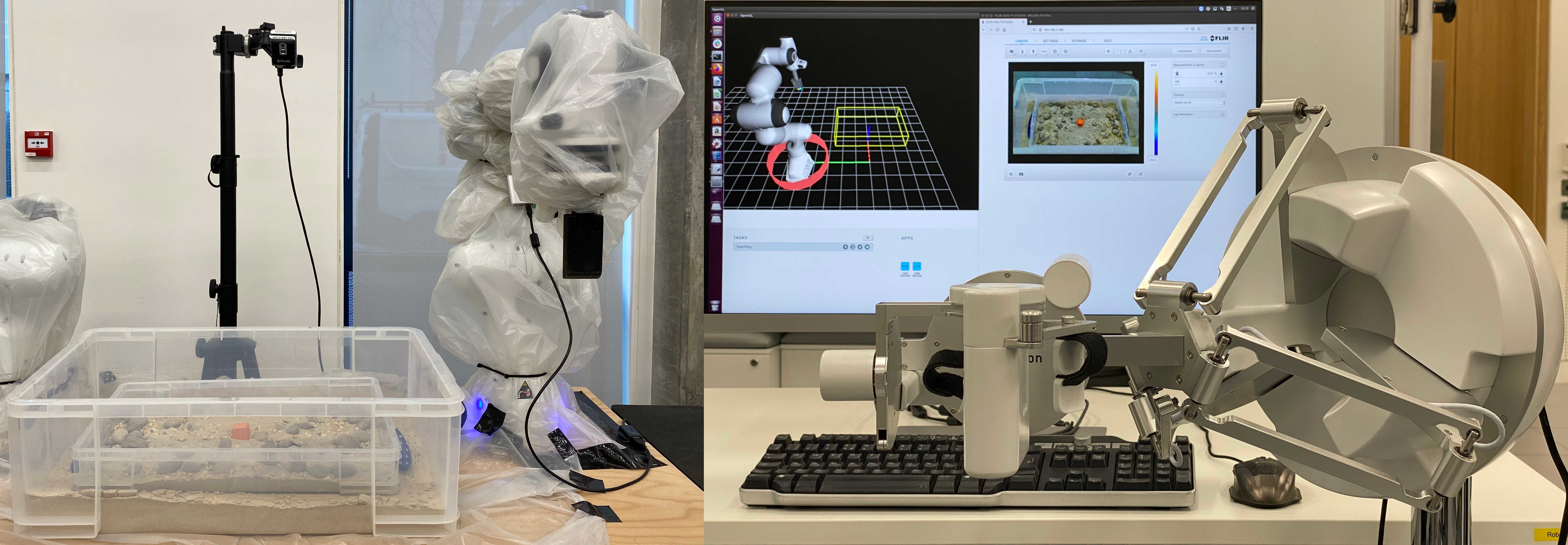
This research uses the setup shown in Fig. 1 to validate the control architecture in Fig. 2 and compares the interaction behaviour of the fractal impedance controller with a traditional impedance controller in teleoperation tasks with low-bandwidth communication and signal delay. We also consider other passive controllers for this application (i.e., energy tank). However, their stability conditions are based on the trading-off of tracking accuracy in order to guarantee stability which is not ideal for dexterity and transparency [25, 17, 19, 27]. The fractal impedance controller does not require such a trade-off.
The contribution of this paper is the development of a passive teleoperation framework based on the Fractal Impedance Controller (FIC) proposed in [13], which being passive guarantees the stability of the system even in the presence of delays or reduced bandwidth. We validate the proposed architecture both with and without significant time delay and reduced bandwidth in the communication channel between the master and the replica, and quantify the performance degradation related to long distance telecommunication. Lastly, we also compare the dexterity of an expert user in 5 tasks in local operations, using both the FIC and a traditional impedance controller on the replica.
The rest of the paper is organised as follows: In section II, the design of the proposed method for passive bilateral telemanipulation is presented. Then, section III discusses the experimental validation followed by section IV, which consists of the experimental results of the carried out experiments. In the end, discussion, the conclusion and future works are provided in section V.
II CONTROL ARCHITECTURE
High levels of transparency between master and replica devices are essential for dexterious interaction in telemanipulation [28]. Ideal transparency implies that the system acts as an identity transformation with infinite bandwidth (i.e, there is effectively no intermediary between the operator and the environment). Our proposed architecture aims at improving system transparency via FIC, which we argue is more robust to discretisation, model-errors, noise and time-delay than a traditional impedance controller.
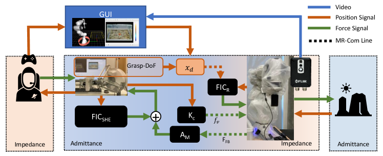
The proposed method for bilateral haptic manipulation (Fig. 2) has two physical interfaces. The first interface, between the operator and the master device (Sigma.7, Force Dimension), has an admittance controller (i.e., ,[5]) that reproduces interaction dynamics at the replica robot’s end-effector. The second interface, between the replica (Panda, Franka Emika) and the environment, behaves as an impedance mimicking the operator input acquired by the master device. We also propose the use of an additional impedance controller – FIC – for Safety and Haptic Enhancement (FIC), generating a virtual force added to the feedback from the replica for providing additional safety to the operator, such as virtual work-space boundaries. The master device is controlled using an admittance controller that includes the Sigma.7 gravity compensation. The master position error () is the input to a proportional controller generating a virtual force () on the replica’s end-effector. The master’s gripper button allows the operator to switch to velocity control, whereby when the gripper is depressed the replica’s desired position () is continuously updated by adding the current master position error to the initial value of until the gripper is released.
Despite these control modalities being useful in dexterous fine interaction, they are not easy to use for large movements. Therefore, we have also implemented a keyboard based input through a GUI to modify the desired pose and autonomously drive the robot to the desired pose. Finally, the GUI is also used to provide visual feedback of the replica’s workspace via a camera.
II-A Master’s Controllers
The master desired wrench command input for the Sigma-7’s admittance controller (as defined in [5]) is sum of the scaled end-effector force () and the FIC:
| (1) |
where is a state dependant diagonal stiffness matrix, is the (diagonal) damping gain, is the wrench measured at the replica’s end-effector and is the scaling factor set to in this work.
II-B Replica’s Controllers
The replica’s controller is the combination of the virtual force from the master (), the FIC, the replica’s inverse dynamics compensation and a null-space controller (in the case of a redundant manipulator):
| (2) |
where is the end-effector Jacobian and is the null space torque ( is the error from the reference pose and are joint velocities). is the inverse dynamics compensation, where is the inertia matrix. is the task-space inertia matrix, is Coriolis’s matrix, and is the gravity compensation vector in joint-space. is the scaling coefficient for the virtual force generated by the operator, and are the diagonal matrices for stiffness and damping gains, respectively.
II-C Fractal Impedance Controller
The FIC is a anisotropic passive controller described in details in [13]. It is used in both FIC and FIC. Thus, generating the following end-effector dynamics:
| (3) |
where is the task-space inertia, is a constant damping, and is the anisotropic state-dependant impedance profile, determined as follows:
Divergence Phase ( or ):
| (4) |
Convergence Phase ():
| (5) |
Where and are the constant and the variable stiffness respectively, is the maximum exertable wrench, is the stiffness during divergence (Eq. 4). is the maximum position error reached during divergence, and controls the stiffness saturation-boundaries, which is calculated as follows:
| (6) |
where is the pose error where is reached. For full explanation of these equations we refer the reader to [13].
III EXPERIMENTAL VALIDATION
We compare our fractal impedance controller to a traditional impedance controller (IC) from the perspective of the operator, as shown in Fig. 2. The traditional impedance controller is similar to the FIC control law (Eq. 2), however, it only has a constant stiffness term. For these experiments, we keep the constant stiffness terms ( for FIC) the same for both controllers. In order to keep IC stable for our experiments, we also had to set its damping term 8 times higher than FIC’s. The values for the three controllers’ parameters used in this paper are reported in Table I. To evaluate transparency, we conduct spectral analysis considering the force signals measured on the replica’s end-effector as input and the velocity produced on the master as output. We also examine the robustness of the controller in the presence of low-bandwidth and time-delayed feedback via experiments with an expert and a naive subject to evaluate whether the stability of the proposed method relies on the operator skill. In summary, the following experiments are performed:
| Master | Replica | ||
| FIC | FIC | IC | |
| 0 | 100 | 100 | |
| 0 | 5 | 5 | |
| 2.5 | 2.5 | 20 | |
| 0 | 1.25 | 1.25 | |
| 0.075 | 0.075 | NA | |
| 1.0472 | 1.0472 | NA | |


-
i)
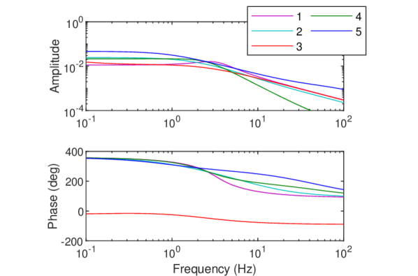
System impulse response: 14 force impulses are applied to the replica’s end-effector using a hammer while the master device is not held. The Matlab2020a (Matworks Inc, US) system identification toolbox is used to derive the transfer functions using the interaction force applied at the replica’s end-effector as the system input and the velocity produced at the master as its output (i.e., ).
-
ii)
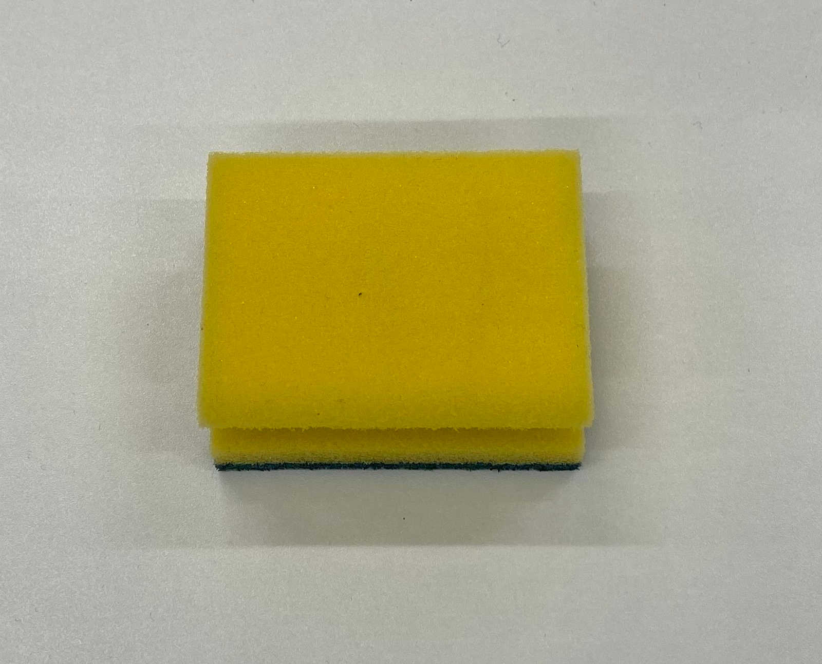
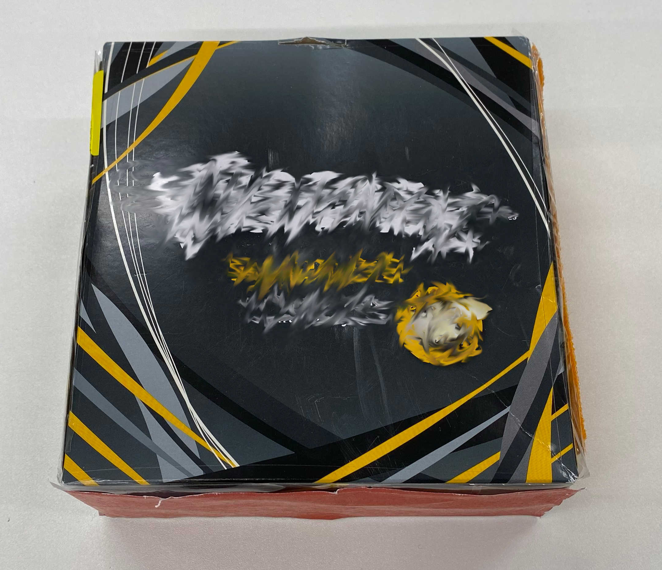
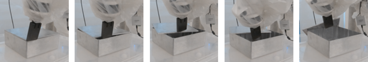
Interaction effects on system response: An expert operator uses the master device to drive the replica robot to contact each of the 5 objects depicted in Fig. 3 before releasing hold of the master device. The selected objects’ dynamics varies from stiff to compliant to evaluate the controllers’ robustness to environmental interaction coupling effects.
-
iii)
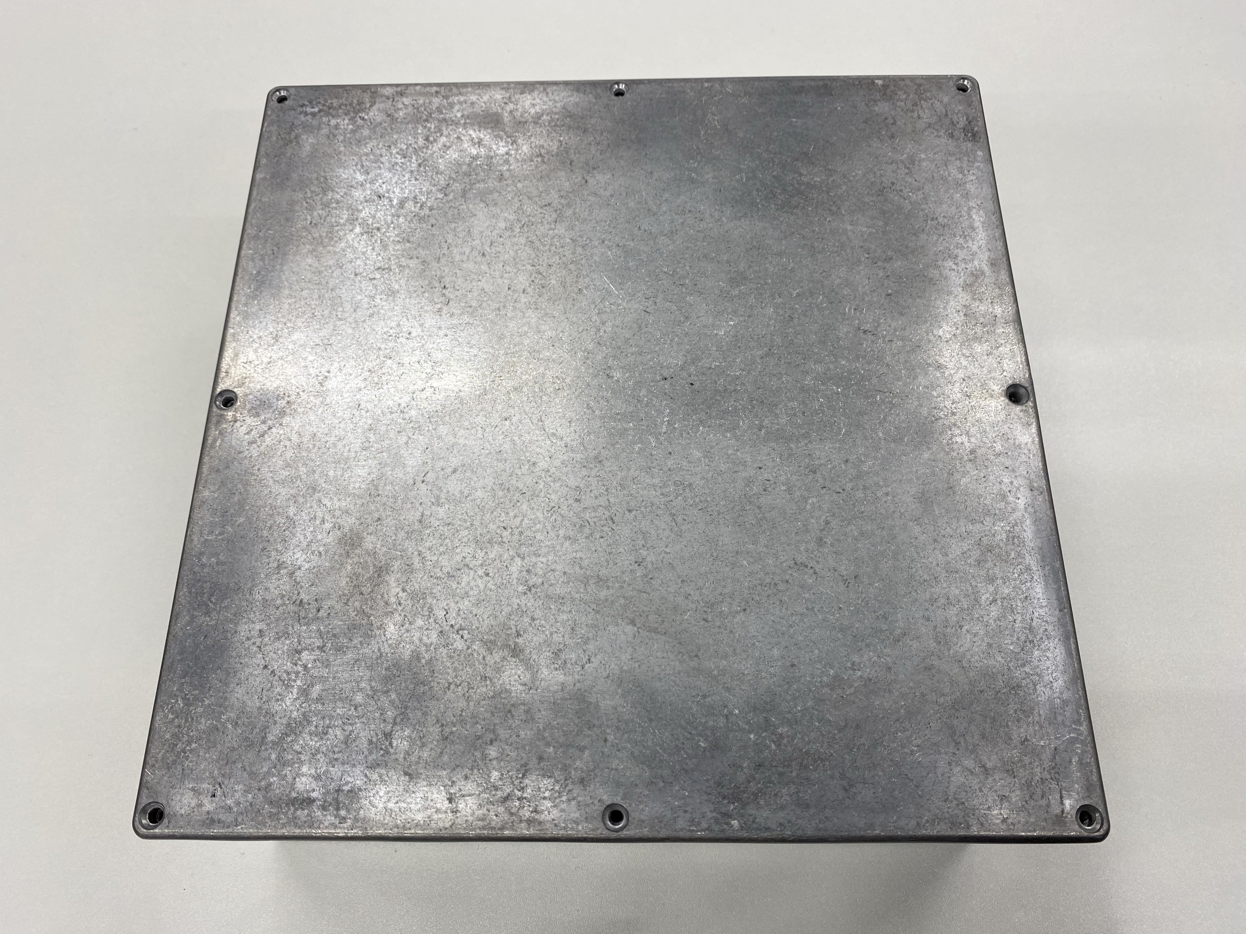
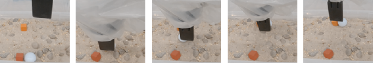
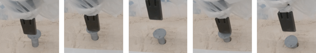
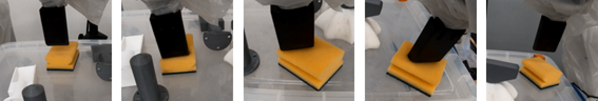
Dexterity comparison in challenging tasks: we test the replica controlled by both IC and FIC, in a sequence of dexterous tasks to evaluate their performances. The tasks are conducted by a skilled operator, which is standard practice in the validation of teleoperation frameworks in robotics [19, 26, 17, 27]. The operator is allowed a single attempt for each task and the choice of the starting controller was alternated to mitigate the operator bias. The tasks are: 1) Removing the lid from the metal box in 3e, 2) Pushing a golf ball to an end-goal on a rough terrain (with sand, gravel, and rocks), 3) Driving a pile through the sand, 4) Diving the sponge in 3c through a course, and 5) Press an E-stop button on a control panel.
-
iv)
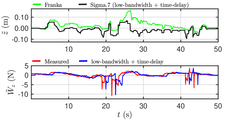
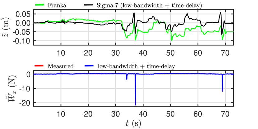
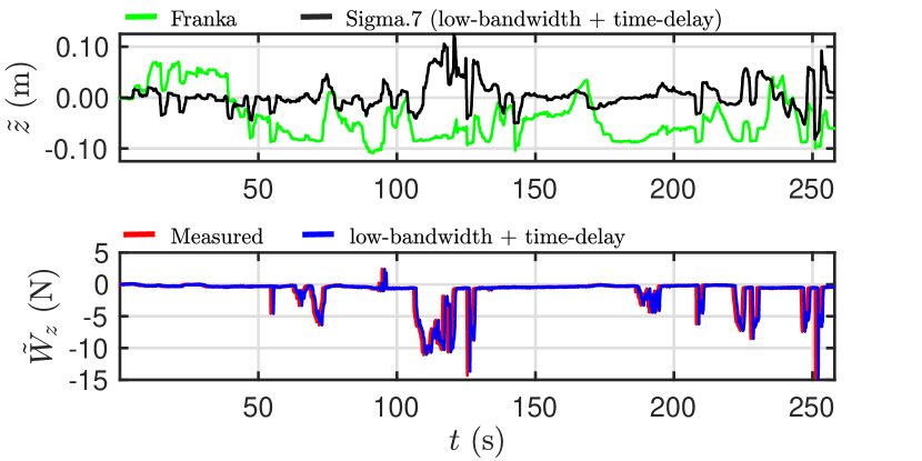
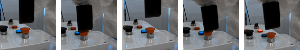
Robustness to Low-Bandwidth Feedback and Time-Delay: We simulate a time-delay between master and replica via an adjustable signal buffer, while an adjustable zero-order hold is used to vary communication bandwidth. The affected signals are feedback force provided as input to the master, the virtual force used to drive the replica’s end-effector (), and the desired pose provided as input to the . We run an experiment where the operator needs to drive the replica to press two E-stop buttons placed apart. We test with both an expert and a naive operator to verify if system stability is independent from operator skill. The following communication conditions between master and replica are tested: 1) Signal sampling frequencies of , and , 2) Signal time delays of , and , and 3) combinations of both low-bandwidth feedback and time-delay.
IV Results
IV-A System impulsive response
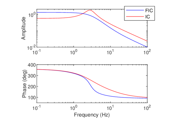
The impulsive response of the two controllers (Fig. 4) show a system cut-off frequency of about 2Hz in both controllers. Although IC has 8x higher damping, it demonstrates an under-damped behavior. On the other hand, FIC’s higher overall stiffness (with lower damping), coupled with the fractal attractor’s autonomous trajectories, allows it to maintain a desirable critically damped behavior.
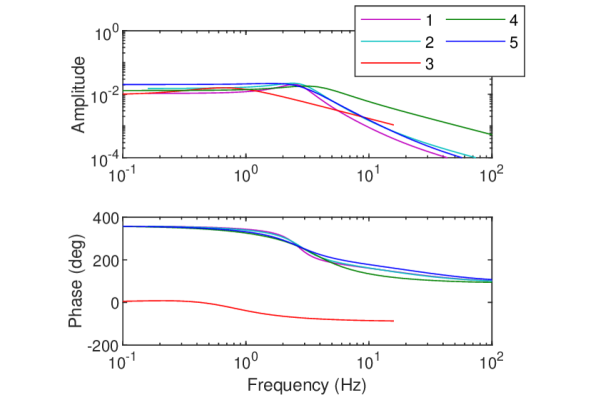
IV-B Interaction effect on system response
Fig. 5 also confirms these characteristics when interacting with objects. However, we also observe a band-pass behaviour due to the user driving the robot via the master device (at least until the replica’s end-effector makes contact with the object), which filters the lower frequencies.
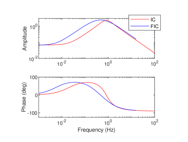
It can also be observed how the band-pass is wider where the replica is driven via FIC controller. Fig. 8 compares the behaviour of the two controllers when interacting with different objects. The data show that the transient behaviour of the proposed method is more variable, and it has a lower attenuation of the input signal.
IV-C Dexterity comparison between the IC and the FIC
The completion times for the 5 tasks performed by an expert operator (using high quality communication between master and replica) are, respectively, , , , and for the FIC. The times when using IC are NA (task failed), , NA (task failed), and , respectively. The data show that the operator is faster in all tasks when executing with the FIC controller. Task 1 failed with IC due to the controller command triggering the robot safety mechanisms. Task 3 also failed with IC due to lack of dexterity. These experiments confirm that the FIC enables better interaction dexterity compared to the IC controller, as highlighted in the attached video.
IV-D Robustness to Low-Bandwidth Feedback and Time-Delay
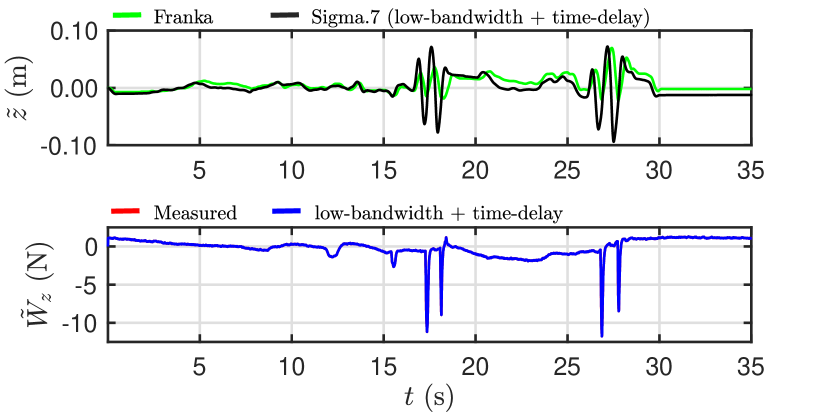
Fig. 6 and Fig. 7 show trajectories recorded for a button pushing task from the expert and naive operators using our proposed method under high quality ( and ) and poor ( and ) signal transmission. Comparing the data we can observe that, as expected, the expert user has more confident movement and better control over the vertical interaction force . Nonetheless, the naive subject can successfully complete the assigned task without triggering the robot safety mechanisms in any of the analysed cases. The completion times are reported in Table II for all tested conditions. They indicate that the expert user is between 2 and 4 times faster than the naive user, but both are able to complete all tasks successfully. Thus, we can conclude that the proposed method is robust to extreme delay and low communication bandwidth, and moreover, controller stability is independent of the operator skill.
V DISCUSSION
We have presented a passive telemanipulation framework based on the Fractal Impedance Control (FIC) which guarantees stability in the presence of delayed and reduced feedback bandwidth. Our results validate that the proposed controller is robust to dynamic interaction with external environments as well as to extremely poor signal transmission between master and replica. Spectral analysis shown in Fig. 5 demonstrates that the proposed method has a wider band-pass and lower attenuation of inputs when driven by a user. Thus our system enables higher transparency for telemanipulation tasks, compared to the traditional impedance controller.
In terms of delays and reduced bandwidth in the communication, the analysis of the controller performance indicates that our method can guarantee stability of interaction during manipulation even in extreme conditions ( and ) without requiring an expert operator. The outcome of the dexterity comparison between FIC and the IC controllers shows that the proposed method allows better maneuvering and has more robust interaction than a traditional impedance controller.
In conclusion, the results show that the proposed method has intrinsic adaptability to different environmental dynamics, even without performing online gain tuning. Robustness to low-bandwidth and time-delayed signals shows its promise for applications in extreme environments such as planetary space exploration. Future work will focus on extending the controller on bi-manual tasks, drilling, cutting and surface finishing.
| Communication Condition | Expert User | Naive User |
|---|---|---|
| , | 31 | 69 |
| , | 39 | 73 |
| , | 41 | 99 |
| , | 49 | 105 |
| , | 51 | 209 |
| , | 57 | 241 |
| , | 61 | 243 |
| , | 63 | 247 |
| , | 66 | 258 |
References
- [1] R. Wen et al., “Force-guided high-precision grasping control of fragile and deformable objects using semg-based force prediction,” IEEE Robotics and Automation Letters, vol. 5, no. 2, pp. 2762–2769, 2020.
- [2] P. Schmaus et al., “Preliminary insights from the meteron supvis justin space-robotics experiment,” IEEE Robotics and Automation Letters, vol. 3, no. 4, pp. 3836–3843, 2018.
- [3] ——, “Continued advances in supervised autonomy user interface design for meteron supvis justin,” in 2019 IEEE Aerospace Conference. IEEE, 2019, pp. 1–11.
- [4] Z. Sun et al., “Learning pregrasp manipulation of objects from ungraspable poses,” in 2020 IEEE International Conference on Robotics and Automation (ICRA). IEEE, 2020, pp. 9917–9923.
- [5] N. Hogan, “Impedance Control: An Approach to Manipulation,” Journal of Dynamic Systems, Measurement, and Control, vol. 107, no. 1, pp. 1–24, 03 1985.
- [6] ——, “A general actuator model based on nonlinear equivalent networks,” IEEE/ASME Transactions on Mechatronics, vol. 19, no. 6, pp. 1929–1939, 2013.
- [7] Z. Li et al., “Compliance control for stabilizing the humanoid on the changing slope based on terrain inclination estimation,” Autonomous Robots, vol. 40, no. 6, pp. 955–971, 2016.
- [8] Y. Li et al., “Force, impedance, and trajectory learning for contact tooling and haptic identification,” IEEE Transactions on Robotics, vol. 34, no. 5, pp. 1170–1182, 2018.
- [9] J. Buchli et al., “Variable impedance control a reinforcement learning approach,” Robotics: Science and Systems VI, pp. 153–160, 2011.
- [10] T. Tsumugiwa et al., “Variable impedance control based on estimation of human arm stiffness for human-robot cooperative calligraphic task,” in Proceedings 2002 IEEE International Conference on Robotics and Automation (Cat. No. 02CH37292), vol. 1. IEEE, 2002, pp. 644–650.
- [11] A. J. van der Schaft and A. Van Der Schaft, L2-gain and passivity techniques in nonlinear control. Springer, 2000, vol. 2.
- [12] T. Hulin et al., “Passivity and stability boundaries for haptic systems with time delay,” IEEE Transactions on Control Systems Technology, vol. 22, no. 4, pp. 1297–1309, 2013.
- [13] K. K. Babarahmati et al., “Fractal impedance for passive controllers,” arXiv preprint arXiv:1911.04788, 2019, Submitted.
- [14] S. Stramigioli et al., “Sampled data systems passivity and discrete port-hamiltonian systems,” IEEE Transactions on Robotics, vol. 21, no. 4, pp. 574–587, 2005.
- [15] J.-H. Ryu et al., “Stable teleoperation with time-domain passivity control,” IEEE Transactions on robotics and automation, vol. 20, no. 2, pp. 365–373, 2004.
- [16] N. Hogan and S. P. Buerger, “Impedance and interaction control,” in Robotics and automation handbook. CRC press, 2018, pp. 375–398.
- [17] F. Ferraguti et al., “An energy tank-based interactive control architecture for autonomous and teleoperated robotic surgery,” IEEE Transactions on Robotics, vol. 31, no. 5, pp. 1073–1088, 2015.
- [18] C. Secchi et al., “Position drift compensation in port-hamiltonian based telemanipulation,” in 2006 IEEE/RSJ International Conference on Intelligent Robots and Systems. IEEE, 2006, pp. 4211–4216.
- [19] M. Franken et al., “Bilateral telemanipulation with time delays: A two-layer approach combining passivity and transparency,” IEEE transactions on robotics, vol. 27, no. 4, pp. 741–756, 2011.
- [20] V. Duindam and S. Stramigioli, “Port-based asymptotic curve tracking for mechanical systems,” European Journal of Control, vol. 10, no. 5, pp. 411–420, 2004.
- [21] T. S. Tadele et al., “Combining energy and power based safety metrics in controller design for domestic robots,” in 2014 IEEE International Conference on Robotics and Automation (ICRA). IEEE, 2014, pp. 1209–1214.
- [22] G. Raiola et al., “Development of a safety-and energy-aware impedance controller for collaborative robots,” IEEE Robotics and automation letters, vol. 3, no. 2, pp. 1237–1244, 2018.
- [23] K. Kronander and A. Billard, “Stability considerations for variable impedance control,” IEEE Transactions on Robotics, vol. 32, no. 5, pp. 1298–1305, 2016.
- [24] C. Schindlbeck and S. Haddadin, “Unified passivity-based cartesian force/impedance control for rigid and flexible joint robots via task-energy tanks,” in 2015 IEEE international conference on robotics and automation (ICRA). IEEE, 2015, pp. 440–447.
- [25] A. Dietrich et al., “Passivation of projection-based null space compliance control via energy tanks,” IEEE Robotics and automation letters, vol. 1, no. 1, pp. 184–191, 2015.
- [26] F. Ferraguti et al., “A tank-based approach to impedance control with variable stiffness,” in 2013 IEEE International Conference on Robotics and Automation. IEEE, 2013, pp. 4948–4953.
- [27] M. Minelli et al., “An energy-shared two-layer approach for multi-master-multi-slave bilateral teleoperation systems,” in 2019 International Conference on Robotics and Automation (ICRA). IEEE, 2019, pp. 423–429.
- [28] D. Zhou and K. Tadano, “Relationship between system parameters and operator’s haptic sensation in bilateral controlled master–slave system,” International Journal of Human–Computer Interaction, vol. 36, no. 2, pp. 143–155, 2020.