Dynamically Tuned Arrays of Polariton Parametric Oscillators
Abstract
Optical parametric oscillations (OPOs) – a non-linear process involving the coherent coupling of an optically excited two particle pump state to a signal and an idler states with different energies – is a relevant mechanism for optical amplification as well as for the generation of correlated photons. OPOs require states with well-defined symmetries and energies: the fine-tuning of material properties and structural dimensions to create these states remains a challenge for the realization of scalable OPO-based functionalities in semiconductor nanostructures. Here, we demonstrate a pathway towards this goal based on the control of confined microcavity exciton-polaritons modulated by the spatially and time varying dynamical potentials produced by a surface acoustic waves (SAW). The exciton-polariton are confined in m-sized intra-cavity traps fabricated by structuring a planar semiconductor microcavity during the epitaxial growth process. OPOs in these structures benefit from the enhanced non-linearities of confined systems. We show that SAW fields induce state-dependent and time-varying energy shifts, which enable the energy alignment of the confined levels with the appropriate symmetry for OPO triggering. Furthermore, the dynamic acoustic tuning, which is fully described by a theoretical model for the modulation of the confined polaritons by the acoustic field, compensates for fluctuations in symmetry and dimensions of the confinement potential thus enabling a variety of dynamic OPO regimes. The robustness of the acoustic tuning is demonstrated by the synchronous excitation of an array of confined OPOs using a single acoustic beam, thus opening the way for the realization of scalable non-linear on-chip systems.
I Introduction
Microcavity exciton-polaritons (polaritons) are light-matter quasi-particles resulting from the strong coupling between photons confined in a semiconductor microcavity (MC) with excitons in a quantum well (QW) embedded in the MC spacer [1]. Polaritons inherit the low effective mass from their photonic component, which gives them spatial coherence lengths of several m. The polariton properties can thus be modified by confinement within m dimensions as compared to the nm dimensions normally required to induce quantum shifts in electronic systems. In addition, the excitonic component of polaritons gives rise to inter-polariton interactions and, thus, non-linearities much stronger than between photons. Finally, polaritons are composite bosons and can form Bose-Einstein-like condensates (BECs) at temperatures several orders of magnitude higher than cold atoms [2].
The mixed light-matter nature of polaritons brings the rich physics of correlated systems to an all-semiconductor platform [3, 4]. It was early recognized that the strong inter-polariton interactions and the peculiar shape of the polariton energy dispersion enable stimulated parametric amplification with very large gain [5, 6] as well as optical parametric oscillations (OPOs) [7, 6, 8]. Here, two pump () polaritons resonantly excited at the inflection point of the lower polariton dispersion can scatter into signal () and idler () states while conserving energy and momentum [9, 10, 11, 12]. The OPO process is a convenient approach for direct excitation of polariton condensates by stimulated scattering to the states at the bottom of the dispersion [7]. This excitation scheme avoids the formation of a high-density reservoir of excitons with high in-plane momentum, which normally occurs for non-resonant optical injection.
The OPO process provides a pathway for the efficient generation of correlated and entangled photons. Different approaches have been proposed to enhance the efficiency of the process including the engineering of the polariton density of states by using multiple cavities [13] and spatial confinement [14]. Confinement creates a discrete spectrum of polariton levels. The latter can act as pump, signal, and idler states, provided that the symmetry and energy spacing required for OPO are satisfied. This approach profits from the high density of polaritons that can be excited in confined potentials, which enhances the non-linear interactions required for OPO formation. In addition, since OPO properties are controlled by the dimensions of m-sized polariton traps, a further advantage of confinement is the scalability arising from the combination of multiple OPO structures on the same polariton MC. The design of confined OPO levels with equally spaced pump, idler, and signal states with the appropriate symmetries to enable mutual non-linear interactions remains, however, a challenging task. The studies in Ref. [14] show that this requirement can be satisfied by the confined states of square pillars etched in a (Al,Ga)As polariton MC. However, even a smallest deviation in the potential shape results in non-equidistant energy spectrum, thus preventing OPO excitation.
In this work, we demonstrate a pathway for the efficient generation of confined polariton states with the appropriate symmetry and energy alignment for OPOs via the dynamic energy tuning by a surface acoustic wave (SAW). The studies are carried out in intra-cavity polariton traps defined in the spacer layer of an (Al,Ga)As MC fabricated by molecular beam epitaxy (MBE), cf. Fig. 1. We show that the spatially dependent SAW fields induce state-dependent energy shifts of the confined levels, which enable the alignment of levels with the appropriate symmetry for OPO triggering. Spatially resolved wave function maps of OPO states prove that the signal and idler states must have same parity, in agreement with the predictions of a model developed to account for non-linear interactions between confined levels in the contact approximation regime [3]. Time-resolved investigations prove the dynamic character of the acoustic OPO triggering at multiples of the SAW frequency. Finally, the acoustic modulation enables robust OPO triggering over a wide range of excitation conditions. In particular, we demonstrate the synchronous tuning of an array of confined OPOs using a single SAW beam, thus proving the feasibility of scalable OPO systems.
II Experimental Details
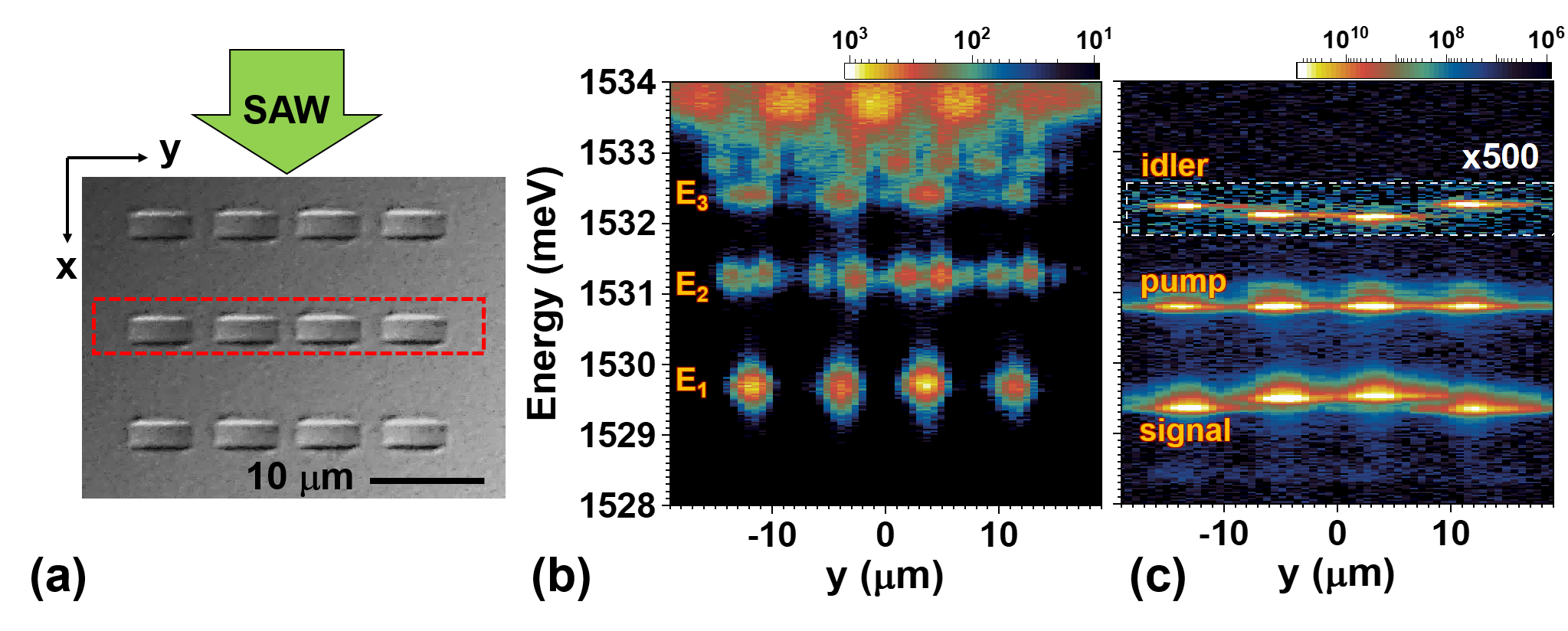
Confined polariton states employed here originate from m-sized intra-cavity traps created within the spacer layer of an (Al,Ga)As MC. The traps were produced by etching the spacer layer of the MC between growth steps by molecular beam epitaxy (MBE). The sample was grown on a GaAs (001) substrate having the structure schematically illustrated in Fig. 1(a). During the MBE growth run, the lower distributed Bragg reflector (DBR) and the MC spacer region containing three pairs of 15 nm-thick GaAs QWs centered at the anti-nodes of the optical field were deposited and then terminated by a 120 nm-thick Al0.15Ga0.85As layer. The sample was then removed from the MBE chamber and patterned by means of photolithography and wet chemical etching to form 12 nm-high and a few m-wide mesas with different shapes. For the final growth step, the sample was reinserted in the MBE chamber for the deposition of the upper DBR. The lower and upper DBRs consist of 58.7 nm and 65.8 nm-thick pairs of AlGaAs/AlGaAs with different Al compositions and
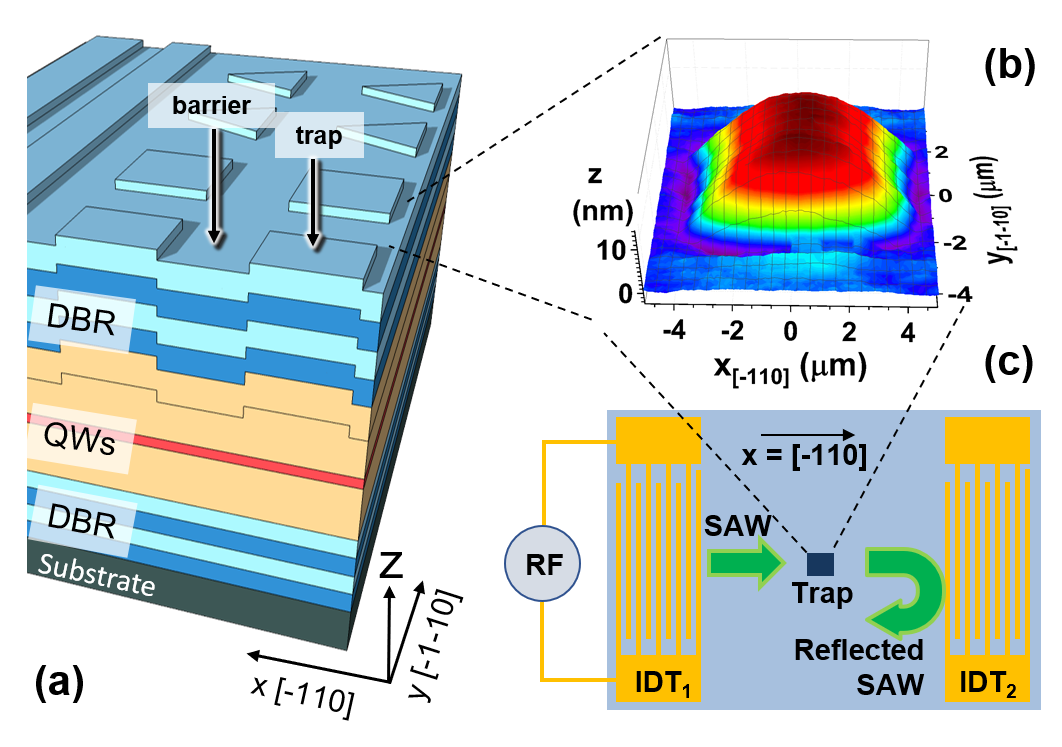
The etching of the MC spacer layer results in a blueshift of the bare optical mode of the MC by 9 meV. As a consequence, the energy of the lower polariton mode in the etched regions becomes approx. meV higher than in the non-etched areas. Polariton traps with an energy barrier can then be formed by enclosing a m-sized non-etched region by etched areas. Due to the conformal nature of the MBE growth, the lateral dimensions of the traps can be estimated by measuring the surface relief of the MC, as illustrated in the Fig. 1(b) for a square trap with nominal lateral dimensions of m2. The anisotropic MBE growth yields traps with different profiles along the trap sides oriented along the and surface directions. A detailed analysis of AFM profiles from the traps presented in Secs. LABEL:SM:Intra-cavity_polariton_traps of the Supplementary Material (SM) shows that the confinement potential is mirror-symmetric with respect to vertical planes and [cf. Fig. 1(b)] but with different profiles along the two directions.
The spectroscopic studies were performed at a temperature between 6 and 10 K in an optical cryostat with radio-frequency (rf) feedthroughs for the excitation of SAWs. We have measured the photoluminescence (PL) of small square traps (dimensions m) placed within a SAW delay line formed by two single-finger interdigital transducers (IDTs). The latter were designed for launching SAWs along the surface direction with a wavelength of m (corresponding to an acoustic frequency MHz at 10 K). The delay line forms an acoustic resonator with a quality factor of 4700 [15]. Care was taken to match the location of the traps with the anti-nodes of the SAW strain field. Time-resolved studies of the OPO dynamics were carried out by detecting the PL with a streak camera synchronized with the rf-signal used to excite the SAW resonator.
III Results
III.1 Confined polaritons in intra-cavity traps
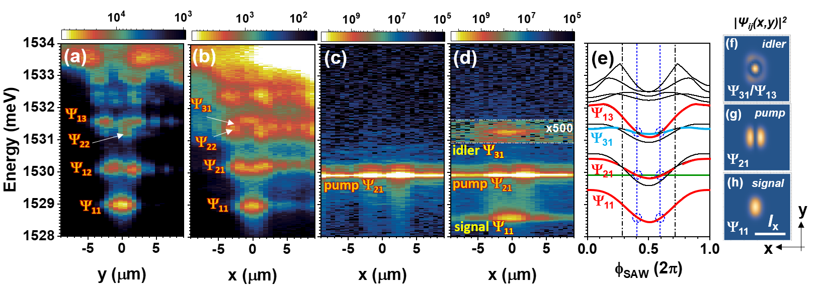
Figure 2(a) and 2(b) compare PL spectral maps of a square trap with nominal dimensions of m2 projected on the and planes, respectively. These maps were recorded under low-density non-resonant optical excitation conditions by collecting the PL with spatial resolution along two perpendicular directions, thus yielding the projection of the squared wave functions () of the confined polariton levels on the and axes, respectively. The and indices denote the number of lobes of along the and directions, respectively.
The polariton states in the intra-cavity traps can be approximated by those of a rectangular one with infinite barriers and dimensions along the and directions, respectively, which can be classified by indices , and ) according to:
| (1) |
Here is Planck’s constant, the reduced polariton mass, and the lower polariton energy in the absence of lateral confinement. The corresponding wave functions can be written as:
III.2 OPO in intra-cavity traps
According to Eq. (1), the confined levels with the set are equidistant in energy for , thus satisfying the energy requirements for OPOs. The lowest three confined levels in Fig. 2(a), however, do not follow this behavior. In addition, the levels and are not degenerate, cf. Fig. 2(a & b). These discrepancies arise from the deviation of the confinement potential from a perfect square shape due to the anisotropic effects during the MBE overgrowth (cf. Sec. LABEL:SM:Intra-cavity_polariton_traps for details) [16]. The impact of the anisotropic shape on the confined states can be reproduced by assuming in Eq. (1), which lifts the degeneracy of the and states with .
The different inter-level spacings and the symmetry of the states (cf. Sec. IV.2) within prevent OPO excitation by optically pumping of the level. An experimental implementation is illustrated in the PL map of Fig. 2(c). Here, the trap was illuminated by a continuous wave (cw) laser beam slightly red-shifted with respect to the emission in Fig. 2(a)-(b), but within its linewidth. The angle of incidence of the laser (of ) was chosen to match the emission peak in momentum space of the state. In addition, this configuration helps to avoid the specular reflection of the pump. Due to focusing, the excitation beam has an angular spread of . The spatially resolved PL was collected for angles between and with respect to the sample surface. The map shows a slight increase of the Rayleigh scattering due to pump interactions with the lobes of the state superimposed on a background of stray light from the pump laser.
When the SAW is turned on, the intra-cavity trap becomes subjected to an effective modulation potential given by [15]:
| (3) |
Here, and denote the wave vector and phase of the standing SAW field, respectively. Under the acoustic modulation, a signal-idler pair appears at energies equidistant to the pump energy, thus signalizing OPO triggering. A detailed analysis of the dependence of the OPO excitation on the frequency of the rf-drive applied to the IDT (cf. Sec. LABEL:SM:Frequency) reveals that OPO states only appear for rf-frequencies matching the modes of the acoustic resonator, thus unambiguously proving that OPO triggering is induced by the SAW field.
The PL map of Fig. 2(d) also yields information about the symmetry of the confined states participating in the OPO process. In fact, the pump state in this figure has two lobes along , thus indicating that it corresponds to the (rather than the closely lying state). The idler state, in contrast, has a single lobe along located in-between the two lobes of the pump state. This emission pattern does not correspond to the one expected for the state but rather to a superposition of the state and . As will be shown in Sec. IV.2, this state red-shifts under the acoustic modulation to satisfy the OPO energy matching condition within the set of levels displayed in the rightmost panels of Fig. 2.
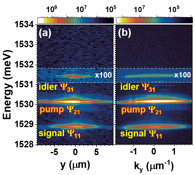
Interestingly, the OPO level configuration is not unique and can be changed by varying the pump energy. Fig. 3 displays PL maps recorded by setting the pump laser energy in resonance to the level (in contrast to the red-shift pumping employed in Fig. 2). The real-space and momentum-space (angle-resolved) maps were recorded in the direction orthogonal to the SAW-propagation and optical excitation. While the OPO-pump state is still , the idler has single emission maximum corresponding to the state. The excited OPO thus corresponds to . We will show in Secs. IV.2 and IV.3 that this OPO mode set is in full agreement with a numerical model for the OPO based on the numerical solution of the Gross-Pitaevskii equation for this particular pump excitation energy.
III.3 OPO switching dynamics
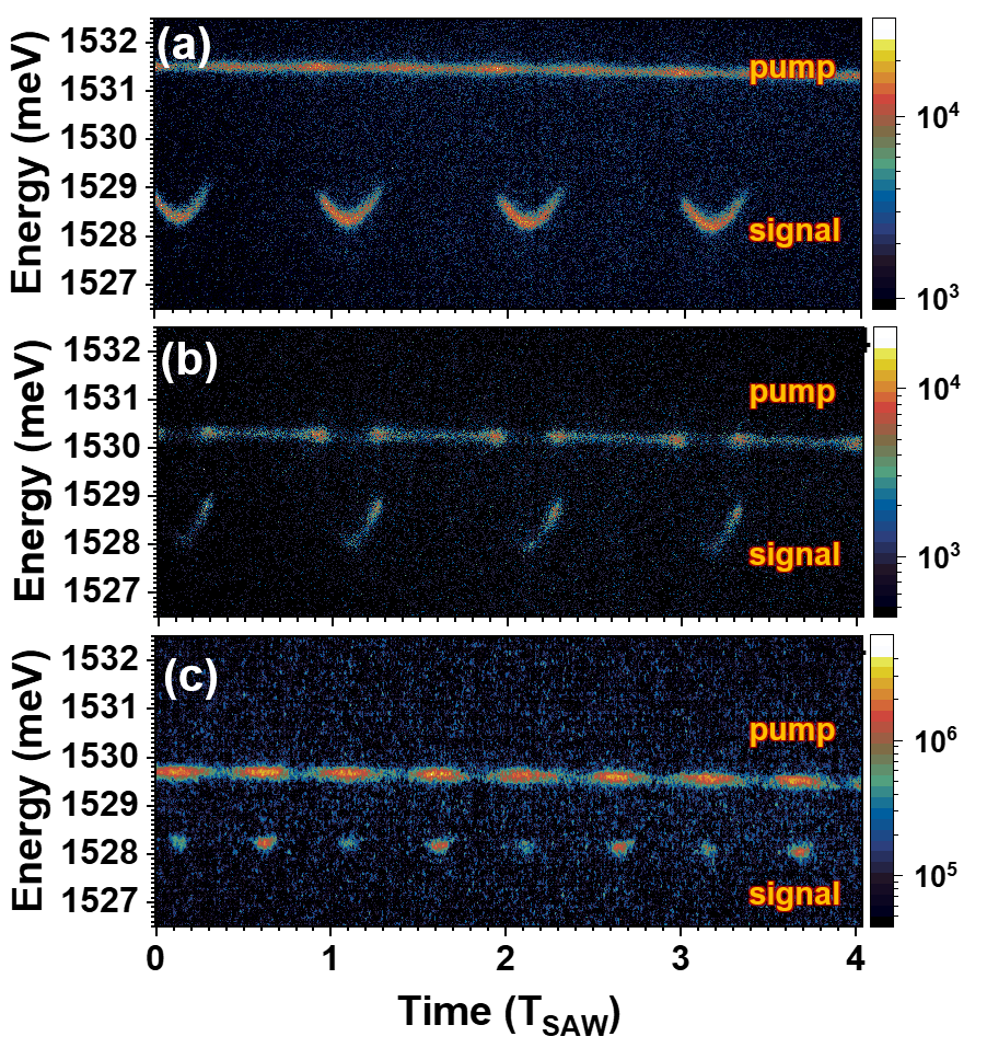
The dynamic character of the acoustic modulation was investigated by analyzing the time dependent PL from the m intracavity trap using a streak camera. Figure 4(a) displays the PL response of polariton condensates in the first and second confined levels recorded under a SAW. This spectrum was acquired under non-resonant excitation at 1.54 eV with an optical power equal to twice the condensation threshold () [2]. The right panel compares the time-integrated PL spectra recorded in the absence of a SAW under weak optical excitation () and in the condensation regime (). The large energy blue-shift of the condensate energies with respect to the ones measured at low excitation are attributed to the polariton interactions with the excitonic reservoir produced by the non-resonant excitation. As discussed in detail in Ref. 15, the modulation by the SAW field leads to a sinusoidal dependence of the emission energy of the confined states.
The left panel in Fig. 4(b) shows the time-resolved emission of an OPO excited in same trap by tuning the pump laser energy to the one from the second confined level at low excitation conditions (right panel). The signal blue-shift in the OPO configuration is negligible compared to the one under the non-resonant excitation [cf. Fig. 4(a)] due to the absence of an excitonic reservoir.
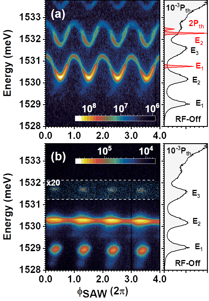
The emission from the signal and idler OPO states only appears during the restricted range of SAW phases for which these states are equidistant to the pump. The time dependence confirms the dynamic nature of the acoustic tuning. The turn-on and turn-off times of the OPO (taken as the time delay for the intensity of the signal state to change by an order of magnitude) is far below the temporal resolution of the present measurements of approx. 100 ps.
The OPO triggering dynamics depends on the SAW amplitude and phase, as well as on the pump energy. Figure 5 illustrates the different dynamic regimes that can be induced by varying the pump energy. At low pump energies, the OPO is normally excited only over a small range of SAW phases. Depending on the SAW amplitude and pump energy, the OPO can be triggered once in a SAW cycle, as in Fig. 5(a & b), or twice in in a SAW cycle, as shown in Fig. 5(c). For high pump energies, the OPO can remain triggered over a range of SAW phases – the latter enables us to follow the dynamic energy modulation of the signal state induced by the SAW field, as illustrated in Figs. 5(a) and 5(b). Note that in all cases, the signal energy for the OPO triggering is always slightly lower than the one for the OPO turnoff, thus showing a hysteretic dependence on the SAW phase. This behavior is attributed to the dynamic energy shifts of the OPO states arising from polariton-polariton interactions. Once the OPO is triggered, the SAW-induced energy shifts of the OPO levels can be counteracted by changes in the polariton density induced by the stimulated scattering to the signal and idler states. In this way, it becomes possible to fulfill the OPO energy conservation requirement for a range of SAW phases and energies of the pump state.
III.4 OPO arrays
We now demonstrate that the acoustic triggering is very robust against fluctuations in trap size and energies, thus making it possible to synchronously trigger OPOs in an array of traps. The studies were carried out in a square array of m2 traps with a pitch of m schematically depicted in Fig. 6(a). Figure 6(b) displays a PL map, recorded under weak non-resonant excitation and absence of SAW by collecting the PL within the area indicated by the dashed square in the Fig. 6(a). The large spatial separation between the traps prevents tunnel coupling between them. The map thus reveals a series of confined states with almost identical energy spectrum for all traps. OPO experiment conditions are identical to the single m2 trap discussed above. Figure 6(c) shows the corresponding PL map obtained by pumping the array slightly below the level in the presence of the acoustic field. OPO is activated in all intra-cavity traps with correlated triggering times determined by the SAW phase at the trap location. Similar to the single trap [cf. Fig. 2(c)], no OPO excitation is observed in the absence of a SAW. The variations of the signal and idler energies on trap position arises from the Gaussian shape of the exciting laser beam, which populates the traps with different polariton densities. These fluctuations, however, do not prevent OPO triggering in all lattice sites under the acoustic modulation.
IV Discussions
IV.1 Acoustic modulation of confined levels
The state dependent acoustic energy tuning mainly relies on the SAW strain field. The latter modulates the excitonic component of polariton via the deformation potential mechanism as well as the photonic component due to modulation of the thicknesses and refractive indices of the MC layers [17, 18]. These two modulation mechanisms add in phase for the present sample and lead to the effective standing polariton potential given by Eq. (3).
The symmetry and time evolution of the polariton levels under a standing acoustic fields can be understood by using perturbation theory to calculate the impact of the dynamical potential [cf. Eq. (III.1)] on the confined levels given by Eq. (1). The acoustically induced energy shifts of the can be expressed as (see Sec. LABEL:SM:Acoustic_Modulation for details):
The acoustic modulation thus introduces a spatial distortion of the confinement potential, which is dictated by the instantaneous amplitude of the standing field as well as by the ratio between the trap dimensions and the acoustic wavelength. The corresponding energy shifts are independent of the mode index but reduce with increasing . This behavior arises from the fact that the lobes of the wave function are centered on the SAW anti-nodes, thus experiencing the full strain-induced energy modulation. The lobes, in contrast, are oriented along the SAW propagation direction and, thus, probe different phases of the standing SAW field. These state-dependent shifts enable the dynamic energy tuning for OPO triggering over a wide range of trap geometries (see Sec. LABEL:SM:Acoustic_Modulation). In particular, the OPO states in a perfect square trap become equidistant in energy by selecting the SAW amplitude and phase to satisfy:
| (5) |
In order to determine the nature of the OPO states, we first examine the impact of the SAW on the energy of the states given by Eq. (III.1). Figure 2(e) displays the energy evolution of the confined polariton levels with the SAW phase, . The calculations were carried out using a numerical approach that takes into account the measured spatial profile of the traps (see Sec. LABEL:SM:Intra-cavity_polariton_traps for details), but neglects polariton-interactions. A more realistic model taking into account interactions will be presented in Sec. IV.3. The vertical dash-dotted black lines mark the nodes of the SAW strain field, where the polariton states are identical to the ones of an unperturbed trap. The states within set are approximately equidistant at this phase, but, for symmetry reasons presented in Sec. IV.2, do not interact. The vertical dashed blue lines indicate the phases for which the OPO energy matching requirement becomes satisfied for the set . We attribute the PL features in Fig. 2(d) to an OPO involving these states. This assignment is supported by a comparison of the PL maps with their calculated wave squared function at the matching SAW phase displayed in Figs. 2(f)-(h). The pump state has thus a predominantly character with two lobes along . The idler state results from the SAW-induced red-shift of the unperturbed state, which mixes with the state. The idler state, thus acquires the symmetry shown in Fig. 2(f).
When the pump energy is in resonance or blue-shifted with respect to the state, the OPO assumes the configuration (cf. Fig. 3) with an idler state.
IV.2 Symmetry of the OPO states
The previous sections have shown that acoustic tuning enables the excitation of OPO in intra-cavity traps over a wide range optical and acoustical excitation conditions. One interesting question is why it is not possible to trigger an OPO in the configuration , which has equally separated states for a perfect square potential. In fact, we show in the SM (Sec. LABEL:Acoustically_induced_energy_tunning) that deviations from a square shape can also be corrected by the acoustic field. The required field amplitudes are in this case much smaller than those given by Eq. (5) for the energy matching of the states.
The inability to excite an OPO arises from symmetry requirements of the non-linear process responsible for OPO triggering, a critical process to initiate parametric oscillations. OPO triggering initiates when fluctuations in population leads to the occupation of the pump state by two polaritons. The latter creates a non-adiabatic and non-linear potential that couples the initial two-polariton state to the final state consisting of particles in a superposition of signal and idler states. In the contact approximation for polariton-polariton interactions,[19, 20] the perturbed two-polariton state represented by can be expressed as:
| (6) |
The coupling Hamiltonian can be expressed as
| (7) |
where denotes the effective polariton-polariton coupling strength. The non-linear coupling thus enables the scattering of pump polaritons to the idler and signal states required to trigger the stimulated scattering leading to parametric oscillations and amplification.
Equation (7) has important consequences for potentials with mirror symmetry, such as the ones created by the intra-cavity traps studied here. The confined states in these potentials have a well-defined parity. Since in Eq. 7 is always an even function, a non-vanishing coupling requires idler and signal states with same parity, i.e., states with indices () differing by an even number. This condition is satisfied for the sets and but not for , in full agreement with the experimental results.
The previously mentioned symmetry requirements remain valid under a standing SAW field, as long as the traps are centered at a field anti-node, since in this case the acoustic perturbation does not affect the mirror symmetry of the trap potential. If, however, the SAW field has a traveling component (or if the trap is displaced from the anti-nodes of a standing field), it will mix states with different parities and enable other OPO configurations.
IV.3 Driven-dissipative simulations of the OPO dynamics
We present in this section a theoretical analysis based on the numerical solution of the driven-dissipative Gross-Pitaevskii equation (GPE) for the lower-polariton field in an intra-cavity trap subjected to an optical field ( with ) as well as to the acoustic modulation potential given by Eq. (3). In contrast to the single-particle calculations presented above, the GPE solutions implicitly account for the polariton non-linearity leading to OPO formation. In atomic units, the GPE can be expressed as:
| (8) | ||||
Here, , and are lower-polariton dispersion, decay rate and polariton-polariton interaction, respectively. The dimensions of the intra-cavity trap were determined from AFM height maps, see Table LABEL:tab:SMT1. The parameters for the trap potential and the SAW modulation amplitude were the same as in the experiments. More details of the calculations procedure are summarized in Sec. LABEL:Numerical_Simulation_of_the_acoustically_driven_OPO.
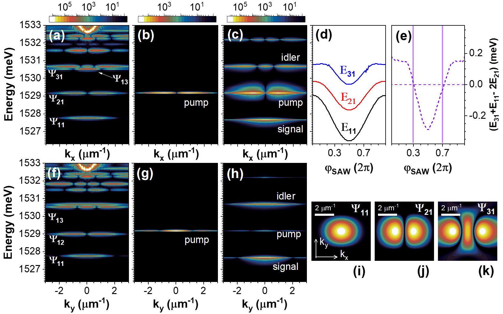
Figures 7(a) and 7(f) display the wave-function projections of the polariton states (in momentum space) calculated for low power, non-resonant optical excitation of the trap. The central panels [Figs. 7(b) and 7(g)] show the corresponding maps under polariton injection into the state, which blue-shifts due to the polariton-polariton interactions. In agreement with the experimental results of in the absence of a SAW, no OPO is observed under these conditions. In contrast, once the SAW potential is added, the signal and idler states appear in the simulated spectra [cf. Figs. 7(c) and 7(h)]. We emphasize here the excellent agreement between the calculated wave function projection of Fig. 7(h) and the experimental momentum-resolved PL map of Fig. 3(b).
The wave functions of the OPO states are illustrated in Figs. 7(i)-(k) correspond to the ones expected for an OPO involving the state set . The dependence of their energy on the SAW phase, which is summarized in Figs. 7(d) and 7(e), shows that the OPO energy matching condition becomes satisfied twice in a SAW cycle for and 0.7 rad.
IV.4 Idler-signal intensity ratios
The OPO process yields pairs of signal and idler polaritons: the same applies for the simulation of the Fig. 7(c,h) that predicts almost identical amplitudes for the signal and idler states. The PL yield from these states depends on how the polaritons decay to photons and may differ considerably due to differences in the scattering rates, Hopfield coefficients, emission pattern, and photon re-absorption. As a result, the emission from idler states is normally much weaker than the signal one. The latter is a main drawback for applications as sources of correlated photons, which ideally require comparable intensity ratios.
The ratio between the integrated emission intensity of the signal and idler in the present studies covers a wide range extending from 20 to 500. For comparison, the OPOs based on confined polariton states reported in Ref. [14] have ratios ranging from approx. 5 to 100, depending on the excitation intensity, which compare with the range from 5 to 10 predicted by theoretical studies presented in the same manuscript. The same ratio increases to to in polariton OPOs based on tripple microcavities [13].
The high inferred from Figs. 2-6 is partially due to an inefficient collection of the idler emission. In particular, the emission in the PL maps will appear very weak if the idler state has a spatially-extended wave function or, as discussed in Sec. III.2, an emission node along the collection axis. We estimate that the limited collection of the idler emission, which can be eliminated by a full measurement of the wave functions, induces an increases of the measured by a factor between 3 and 5.
Another mechanism leading to a large arises from the higher photonic content of the signal states in comparison to the idler states in the present sample. The energy difference between signal and idler states is less than half of the Rabi splitting, so that the large ratios can not be solely attributed to differences in the Hopfield coefficients. Finally, the large may also arise from decay paths from the pump to the low lying signal states (e.g., by a thermal process). Figure 2(d) shows, however, that the signal state only emits under OPO excitation, thus proving the absence of a parallel excitation path. We suggest that the weak photon yield of the idler results from the strong dephasing arising from the coupling with closely lying energy levels. The acoustic field may play a role in this process: in particular, the SAWs employed here also carry piezoelectric fields, which interact strongly and can efficiently mix electronic states. Future acoustic modulation studies using non-piezoelectric SAWs [21] will help to clarify this issue.
V Summary and Outlook
We have demonstrated an efficient and versatile approach for the dynamic control of the scattering pathways of confined polariton condensates based on the modulation by spatially and time-varying potentials produced by SAWs. A unique feature arising from the spatial dependence of the SAW field is the ability to dynamically control the energy of individual polariton states in a confined potential. Here, the SAW is applied to tune the energy states of confined exciton-polariton condensates to enable OPOs. We demonstrated that the acoustic OPO requires not only the matching of the energy energy-level separation, but also signal, pump, and idler states with the appropriate symmetry. The experimental studies have been complemented by a theoretical framework, which accounts for the required symmetry of the confined states and also provides a quantitative determination of the energy tuning parameters. Finally, we have presented experimental results confirming the dynamic character and the robust nature of the acoustic tuning, which enables OPOs under a wide range of excitation conditions.
A natural future step will be the exploitation of acoustically tuned OPOs for the generation of entangled photons from a single trap and arrays. We anticipate that one of the challenges will be to control the mismatch in emission intensity between the signal and idler states. The theoretical framework together with the ability to develop polariton confinement potentials with the appropriate symmetry are an excellent starting point to reach this goal.
The ability to synchronously tune several OPOs is one further advantage of the dynamic acoustic tuning. This functionality is demonstrated by the excitation of an array of confined OPOs using a single acoustic beam. The modulation of the individual polariton traps at the array nodes appropriately tunes the confined levels and counteracts unavoidable energy fluctuations. Furthermore, the OPO emission from the array sites is correlated by the SAW phase. The time jitter of the emission depends on the fluctuations in the trap properties and can be minimized by increasing the SAW amplitude. The photon pairs are emitted not only at well-defined locations within the array but also at well-determined times, a feature which can enhance the fidelity of such a source of correlated photons.
As a final remark, we point out that strain fields interact with a wide variety of excitations in solid state systems. The dynamical acoustic tuning reported can thus be applied to a wide variety of systems, thus providing the robustness in operation required for the realization of scalable on-chip systems.
Acknowledgements: We thank M. Ramsteiner and S. Krishnamurthy for discussions and for a critical review of the manuscript. We also acknowledge the technical support from R. Baumann, S. Rauwerdink, and A. Tahraoui in the sample fabrication process. We acknowledge financial support from the German DFG (grant 359162958) and from the QuantERA grant Interpol (EU-BMBF (Germany) grant nr. 13N14783).
References
- Weisbuch et al. [1992] C. Weisbuch, M. Nishioka, A. Ishikawa, and Y. Arakawa, Observation of the coupled exciton-photon mode splitting in a semiconductor quantum microcavity, Phys. Rev. Lett. 69, 3314 (1992).
- Kasprzak et al. [2006] J. Kasprzak, M. Richard, S. Kundermann, A. Baas, P. Jeambrun, J. M. J. Keeling, F. M. Marchetti, M. H. Szymańska, R. André, J. L. Staehli, V. Savona, P. B. Littlewood, B. Deveaud, and L. S. Dang, Bose-Einstein condensation of exciton polaritons, Nature 443, 409 (2006).
- Carusotto and Ciuti [2013] I. Carusotto and C. Ciuti, Quantum fluids of light, Rev. Mod. Phys. 85, 299 (2013).
- Sanvitto and Kena-Cohen [2016] D. Sanvitto and S. Kena-Cohen, The road towards polaritonic devices, Nat Mater 15, 1061 (2016).
- Savvidis et al. [2000] P. G. Savvidis, J. J. Baumberg, R. M. Stevenson, M. S. Skolnick, D. M. Whittaker, and J. S. Roberts, Angle-resonant stimulated polariton amplifier, Phys. Rev. Lett. 84, 1547 (2000).
- Saba et al. [2001] M. Saba, C. Ciuti, J. Bloch, V. Thierry-Mieg, R. André, S. S. Dang, S. Kundermann, A. Mura, G. Bongiovanni, J. L. Staehli, and B. Deveaud, High-temperature ultrafast polariton parametric amplification in semiconductor microcavities, Nature , 731 (2001).
- Baumberg et al. [2000] J. J. Baumberg, P. G. Savvidis, R. M. Stevenson, A. I. Tartakovskii, M. S. Skolnick, D. M. Whittaker, and J. S. Roberts, Parametric oscillation in a vertical microcavity: A polariton condensate or micro-optical parametric oscillation, Phys. Rev. B 62, R16247 (2000).
- Langbein [2004] W. Langbein, Spontaneous parametric scattering of microcavity polaritons in momentum space, Phys Rev B 70, 205301 (2004).
- Ciuti [2004] C. Ciuti, Branch-entangled polariton pairs in planar microcavities and photonic wires, Phys. Rev. B 69, 245304 (2004).
- Savasta et al. [2005] S. Savasta, O. D. Stefano, V. Savona, and W. Langbein, Quantum complementarity of microcavity polaritons, Phys. Rev. Lett. 94, 246401 (2005).
- Romanelli et al. [2007] M. Romanelli, C. Leyder, J. P. Karr, E. Giacobino, and A. Bramati, Four wave mixing oscillation in a semiconductor microcavity: Generation of two correlated polariton populations, Phys. Rev. Lett. 98, 106401 (2007).
- Portolan et al. [2010] S. Portolan, O. D. Stefano, S. Savasta, and V. Savona, Emergent entanglement of microcavity polariton pairs, Journal of Physics: Conference Series 210, 012033 (2010).
- Diederichs et al. [2006] C. Diederichs, J. Tignon, G. Dasbach, C. Ciuti, A. Lemaître, J. Bloch, P. Roussignol1, and C. Delalande, Parametric oscillation in vertical triple microcavities, Nature 440, 904 (2006).
- Ferrier et al. [2010] L. Ferrier, S. Pigeon, E. Wertz, M. Bamba, P. Senellart, I. Sagnes, A. Lemaître, C. Ciuti, and J. Bloch, Polariton parametric oscillation in a single micropillar cavity, Appl. Phys. Lett. 97, 031105 (2010).
- Kuznetsov et al. [2019] A. S. Kuznetsov, K. Biermann, and P. V. Santos, Dynamic acousto-optical control of confined polariton condensates: From single traps to coupled lattices, Phys. Rev. Research 1, 023030 (2019).
- Kuznetsov et al. [2018] A. S. Kuznetsov, P. L. J. Helgers, K. Biermann, and P. V. Santos, Quantum confinement of exciton-polaritons in structured (Al,Ga)As microcavity, Phys. Rev. B 97, 195309 (2018).
- Sogawa et al. [2001] T. Sogawa, P. V. Santos, S. K. Zhang, S. Eshlaghi, A. D. Wieck, and K. H. Ploog, Dynamic band structure modulation of quantum wells by surface acoustic waves, Phys. Rev. B 63, 121307(R) (2001).
- de Lima, Jr. and Santos [2005] M. M. de Lima, Jr. and P. V. Santos, Modulation of photonic structures by surface acoustic waves, Rep. Prog. Phys. 68, 1639 (2005).
- Ciuti et al. [2001] C. Ciuti, P. Schwendimann, and A. Quattropani, Parametric luminescence of microcavity polaritons, Phys. Rev. B 63, 041303 (2001).
- Carusotto and Ciuti [2005] I. Carusotto and C. Ciuti, Spontaneous microcavity-polariton coherence across the parametric threshold: Quantum Monte Carlo studies, Phys. Rev. B 72, 125335 (2005).
- Rudolph et al. [2007] J. Rudolph, R. Hey, and P. V. Santos, Long-range exciton transport by dynamic strain fields in a GaAs quantum well, Phys. Rev. Lett. 99, 047602 (2007).
- LaBella et al. [2000] V. P. LaBella, D. W. Bullock, Z. Ding, C. Emery, W. G. Harter, and P. M. Thibado, Monte carlo derived diffusion parameters for Ga on the GaAs(001)- (2x4) surface: A molecular beam epitaxy scanning tunneling microscopy study, J. Vac. Sci. Technol., A 18, 1526 (2000), http://dx.doi.org/10.1116/1.582379 .
- de Lima, Jr. et al. [2006] M. M. de Lima, Jr., M. van der Poel, P. V. Santos, and J. M. Hvam, Phonon-induced polariton superlattices, Phys. Rev. Lett. 97, 045501 (2006).
- Dennis et al. [2013] G. R. Dennis, J. J. Hope, and M. T. Johnsson, Xmds2: Fast, scalable simulation of coupled stochastic partial differential equations, Computer Physics Communications 184, 201 (2013).