[a]Dipartimento di Fisica, Sapienza – Università di Roma, Roma I-00185, Italy \affiliation[b]INFN – Sezione di Roma, Roma I-00185, Italy \emailAddgabriele.piperno@roma1.infn.it
First results on the performance of the PADME electromagnetic calorimeter
Abstract
The PADME experiment, hosted at the Laboratori Nazionali di Frascati in Italy, is dedicated to the dark photon search. It looks for the reaction , where indicates the dark photon. The positrons beam that impinges on electrons, coming from an active diamond target, allows to scan masses up to . In this context, the segmented electromagnetic calorimeter plays a fundamental role, since it measures the final photon four-momentum. It consists of BGO crystals displaced in a cylindrical shape of radius with a central square hole of crystals side, to let Bremsstrahlung radiation pass, to limit the calorimeter trigger rate. Each crystal is read by a HZC XP1911 type B photomultipliers and their signal is digitised by means of a CAEN V1742 board, taking samples at . Here we report in detail the solutions adopted for the calorimeter together with the results obtained in tests performed on a small prototype and on single scintillating units.
Calorimeters, Scintillators, Gamma detectors, Detector design and construction technologies and materials
\collaboration[c]on behalf of PADME collaboration
\proceeding15 Topical Seminar on Innovative Particle and Radiation Detectors (IPRD19)
14-17 October 2019
Siena, Italy
1 Introduction
As a result of many cosmological and astronomical observations we know that only of the mass of the Universe is made of Standard Model (SM) matter. The largest part seems to consist of an invisible form of matter, called Dark Matter (DM) [1]. Despite all these results, DM nature is still unknown.
A possible solution to the problem of its elusiveness is that it lives in a separate sector, named Dark Sector, and that it interacts with the SM only by means of portals. The simplest connection between our world and the Dark Sector can be built introducing a new U(1) symmetry, which adds a new vector boson, the Dark Photon (DP) [2, 3]. Even if the SM particles are neutral under this symmetry, the DP can interact with them via a kinetic mixing with the ordinary photon. Consequently, particles will acquire an effective charge , where is the coupling constant and is the particle electric charge.
A strong point of this model is that it is very predictive, being completely described when the constant and the mass are defined.
Generally the DP search is divided into two classes, depending on the decay channel type: visible or invisible. The first case occurs when there are no DM particles with mass and the boson is forced to decay into SM particles. On the contrary, when DM particles with mass exist, the boson will decay mostly into this kind of particles and the SM channels are then suppressed by a factor .
The DP can also solve other existing tensions of the SM. Depending on the model, it could explain, partially or completely, the discrepancy between the expected value and the measured one of the muon anomalous magnetic moment [4] and the two recent observations known as the Beryllium- and Helium-4 anomaly [5, 6].
2 The PADME experiment
The main aim of the Positron Annihilation into Dark Matter Experiment (PADME), hosted at the Laboratori Nazionali di Frascati, is the search for an invisibly decaying DP. Placed in the laboratories Beam Test Facility [9], it exploits the LINAC to accelerate positrons that then annihilate with electrons coming from a target, to look for the reaction:
Positrons are accelerated up to , while the electrons are at rest in a diamond active target. If produced, a long lived or invisibly decaying can’t be observed by the experiment. On the contrary, the four-momentum can be measured by means of a granular electromagnetic calorimeter. Consequently, the boson can be observed as missing mass that, knowing the initial conditions ( and ), can be measured as (the notation indicates the relativistic four-momentum):
Requiring only the coupling to leptons, the PADME DP search results to be almost model independent.
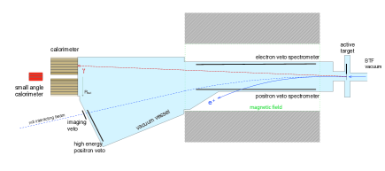
Figure 1 represents the scheme of the detector. Moving from the right to the left of the image, it is composed of the following elements:
-
•
The active target consists of a thick and area polycrystalline diamond, with horizontal and vertical graphitic stripes (only are connected). It returns average information about the beam intensity and position (resolution ). The material is chosen to reduce the Bremsstrahlung cross section, while the thickness is a balance between threshold (the minimum number of detectable positrons), which decreases with thickness, and the beam multiple scattering, which increases with thickness.
-
•
The magnetic dipole, a MBP-S dipole long with gap and field, is placed after the target. Its purpose is to bend beam particles sending them towards the experiment exit, if did not annihilate on the target, or to the charged particle veto system, if they lost part of their energy by Bremsstrahlung.
-
•
The charged particle veto system is the sum of different components: two arrays of plastic scintillating bars inside the magnet gap, one for ( long), one for ( long), needed to identify either positrons that lost a large amount of energy for Bremsstrahlung, or the electrons and positrons produced in interactions. Another array ( long), close to the beam exit, is used to detect positrons that lost a small amount of energy for Bremsstrahlung. Each scintillating bar size is .
-
•
An array of TimePix3 silicon detectors, for a total size of , is positioned at the beam exit to study bunch divergence and structure, thanks to its spatial ( pitch) and time () resolutions.
-
•
On the opposite side of the experiment from the target there is the Electromagnetic Calorimeter (ECal). It presents a central square opening that allows the Bremsstrahlung radiation to pass and to be detected by a faster calorimeter. Additional information on the ECal is given in the next section.
-
•
The small angle calorimeter, placed behind the ECal, has a square shape and is made of lead difluoride (PbF2) crystals. The readout signal is Cherenkov light ( duration), which makes the detector able to sustain an event rate up to hundreds of MHz.
A signal event, , would appear as a single in the ECal with no hits in the small angle calorimeter or vetoes and some missing energy, corresponding to the amount taken away by the boson. Given the beam energy of , the maximum mass that can be explored is .
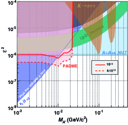
The PADME C.L. sensitivity to an boson that decays in the invisible channel is presented in figure 2. Here the result is given assuming the kinetic mixing model introduced in the previous section and for two different statistics: and positrons on target.
3 The PADME electromagnetic calorimeter
The ECal, together with the active target, is the most important component of the experiment, given that it measures the four-momentum of the photon in the final state. The chosen material is BGO (bismuth germanate) because of its small radiation length () and because the PADME collaboration had the opportunity to reshape and reuse crystals from L3 electromagnetic calorimeter endcaps [10]. It is composed of BGO scintillating crystals of dimensions , displaced in an almost cylindrical shape with a radius of about . Given the long decay time of the BGO scintillation light, , the ECal is not able to sustain high particle rates. Consequently, it has a central square hole of crystals to let the Bremsstrahlung radiation, very intense at small angles, pass and be observed by the faster small angle calorimeter. With the current distance of from the active target, the ECal angular coverage is .
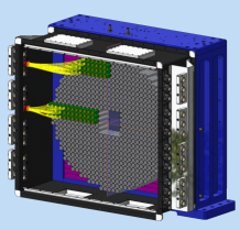
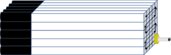
A photomultiplier tube (PMT) is glued to each BGO crystal to form the so called Scintillating Unit (SU). The selected model is the HZC XP1911 type B, which fits the crystals’ square cross section well, thanks to the diameter of , and the BGO emission spectrum, that has a maximum at , at which wavelength the quantum efficiency of the PMT(s) is [11]. A render of the calorimeter is shown in figure 3, in which some of the PMTs (in orange) and signal and HV cables (in yellow) can be seen.
The ECal does not have a honeycomb structure in which to insert the various SUs, due to the fact that it would have spoiled the energy resolution of the calorimeter. Therefore one layer of crystals acts as basis for the next layer. To reduce the light crosstalk, black Tedlar foils are placed between the SUs. These foils are also used to level out any difference in crystal heights by varying the number of layers. Since the start of calorimeter operations in October 2018, SUs have never worked, corresponding to less than the of the total.
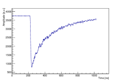
SUs signals are digitised by means of CAEN V1742 boards. Each board is equipped with DRS4 chips, for a total of channels. The channels dynamic range is with a 12-bit precision, while the number of sampled points is . These boards can acquire data at different sampling frequencies: , and . Given the long BGO signals (example in figure 4), the selected one is .
Temperature variations are extremely important when using BGO, because its light yield varies as . To reduce as much as possible this variability a new air conditioning system was installed in the BTF. It is foreseen that the temperature will remain within the desired value. In addition, PT1000 are glued on crystals to monitor their temperature: SUs have a thermometer on their back, close to the PMT, while other have two sensors glued on the side, at and at of crystal length, to probe any dependency on the distance from the front face.
3.1 Scintillating units calibration with 22Na
Before inserting the SUs in the ECal, each of them has been calibrated by means of a 22Na source. The reason for the choice of this isotope is to exploit its back-to-back emission of s coming from an annihilation. The calibration setup consists of a SUs matrix in front of which the source is moved by a couple of step motors. The trigger signal is provided by a LYSO crystal read by a SiPM, positioned on the other side of the source with respect to the SU: a BGO window is acquired every time that the LYSO signal exceeds a threshold. In figure 5 a scheme of the setup is presented.
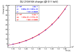
To construct the charge vs HV curve, all the SUs were measured at different voltages in the interval , in steps of , taking about events per voltage. For SUs, this measurement was repeated twice, to evaluate the stability of the obtained results. Each set of data is fitted with the function ( is the charge, is the HV and and are the fit parameters), that allows to get the HV value for the desired gain. An example for a single SU, with the repeated measurement and fit on both groups of data, is given in figure 6.
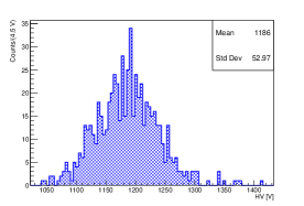
The HV distribution obtained for all the ECal SUs, when requiring a gain of , is shown in figure 7. It presents an average value of with a standard deviation of , meaning that at this gain the typical voltage is well below the maximum safe value of and that there is a low variability between the units. This gain is chosen because it is at the centre of the linearity range and leaves room for signals up to to be fully contained in the DAQ without saturating. This is necessary due to the possibility of having events with more than one photon in the same SU. In these cases the pulse amplitude from each photon may sum to a value larger than the amplitude given by a single particle of the maximum energy.
3.2 Cosmic rays in the electromagnetic calorimeter
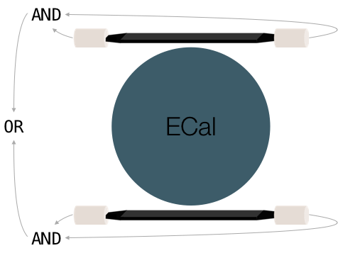
To study and improve the ECal performances, also Cosmic Rays (CRs) are exploited. In figure 8 the CRs trigger structure and logic are shown. It consists of two scintillating paddles, one above and one below the ECal, each one read by two PMTs, one per each side of the paddle. PMTs on the same paddle are in logic AND. The logic OR of these two ANDs gives the trigger signal. The OR is needed to maximise the trigger rate and to acquire also cosmics that cross the ECal diagonally, which pass through a single paddle.
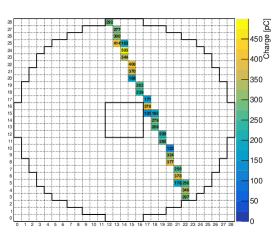
In figure 9 an example of a CR passing through the ECal is shown. The color scale, as the number in the box, indicates the charge integral of the SU pulse in pC.
Using CRs it is possible to evaluate the gain homogeneity between the units and improve the ECal energy resolution [13]. The selection of CRs vertically passing through a crystal ensures a smaller spread of the crossing path and, hence, of the released energy. Starting from this and knowing that the average amount of released energy is always the same, it is possible to equalise the charge spectra of the SUs.
Contemporaneously, with the vertical CRs selection, it is also possible to study the ECal channels efficiency by checking how many times a CR is seen by a unit when it is seen by the SU above and the SU below [13].
3.3 Beam test on a calorimeter prototype
A matrix of pre-production SUs was measured in a test beam at the BTF [14]. The results obtained show an energy resolution compatible with the one from the L3 experiment [10]. In fact the fit to the relative energy resolution, with the function , gives the following parameters: , and . Consequently the target energy resolution of has been achieved.
In the same test beam also the linearity of the charge as a function of the beam energy has been studied and resulted to remain within the up to .
Preliminary studies, using the BTF positron beam directly on the ECal, indicate that it shows an energy resolution similar or better with respect to the one obtained with the prototype [13].
4 Conclusions
The PADME experiment main purpose is the search for a dark photon () that decays into dark matter particles, looking for the reaction . In this context the electromagnetic calorimeter of the experiment plays a fundamental role, allowing the measurement of the final state photon four-momentum and, hence, the boson mass, as the reaction missing mass. In this paper we describe the calorimeter with the solutions adopted during its construction aimed to improve its performance, like the scintillating material choice, the presence of black Tedlar to reduce the light crosstalk, the absence of a metal structure for the calorimeter and the usage of PT1000 sensors for temperature monitoring.
In addition the calorimeter cosmic rays trigger is described, together with the possible studies that can be performed by exploiting this information.
As a last argument, the results obtained with a calorimeter prototype are summarised, showing how the observed performance are in line with design ones.
References
- [1] Y. Akrami et al., Planck 2018 results. I. Overview and the cosmological legacy of Planck, arXiv:1807.06205
- [2] P. Galison and A. Manohar, Two Z’s or not two Z’s?, Phys. Lett. B 136 (1984) 279.
- [3] B. Holdom., Two U(1)’s and charge shifts, Phys. Lett. B 166 (1986) 196.
- [4] M. Pospelov, Secluded U(1) below the weak scale, Phys. Rev. D 80 (2009) 095002.
- [5] A. J. Krasznahorkay et al., Observation of Anomalous Internal Pair Creation in 8Be : A Possible Indication of a Light, Neutral Boson, Phys. Rev. Lett. 116 (2016) 042501.
- [6] A. J. Krasznahorkay et al., New evidence supporting the existence of the hypothetic X17 particle, arXiv:1910.10459.
- [7] M. Raggi and V. Kozhuharov, Results and perspectives in dark photon physics, Riv. Nuovo Cim. 38 (2015) 449.
- [8] M. Battaglieri et al., US Cosmic Visions: New Ideas in Dark Matter 2017: Community Report, arXiv:1707.04591.
- [9] P. Valente et al., Linear Accelerator Test Facility at LNF Conceptual Design Report, INFN-16-04-LNF, arXiv:1603.05651.
- [10] B. Adeva et al., The construction of the L3 experiment, Nucl. Instrum. Methods A 289 (1990) 35.
- [11] http://www.hzcphotonics.com/
- [12] E. Leonardi et al., Development and test of a DRS4-based DAQ system for the PADME experiment at the DANE BTF, J. Phys. Conf. Ser. 898 (2017) 032024.
- [13] PADME coll., Article in preparation.
- [14] M. Raggi et al., Performance of the PADME Calorimeter prototype at the DANE BTF, Nucl. Instrum. Meth. A 862 (2017) 31.