Link Level Performance Comparison of C-V2X and ITS-G5 for Vehicular Channel Models
Abstract
Vehicle-to-everything (V2X) communications plays a significant role in increasing traffic safety and efficiency by enabling vehicles to exchange their status information with other vehicles and traffic entities in their proximity. In this regard, two technologies emerged as the main contenders for enabling V2X communications which have stringent requirements in terms of latency and reliability due to their apparent safety criticality. The first one is the Dedicated Short Range Communications (DSRC) standard (referred to as ITS-G5 in Europe) that is well researched since 20 years and has attained enough technical maturity for current deployment. The second one is the relatively new Cellular-V2X (C-V2X) standard that is nevertheless, based on the 3rd Generation Partnership Project (3GPP) standard family that have successful deployments in almost every corner of the globe. In this work, we compare the link level performance of the Physical Layer (PHY) protocols for both the technologies for different vehicular fading channel models. To this end, we construct and simulate the PHY pipelines and show the performance results by means of Block Error Rate (BLER) versus Signal-to-Noise Ratio (SNR) graphs. Our investigations show that C-V2X performs better than ITS-G5 for almost all the considered channel models due to better channel coding and estimation schemes.
I Introduction
5G networks enable native support for new vertical domains such as vehicular and industrial communications. V2X communication encompasses any form of communication between a vehicle and surrounding traffic entities and it includes different modes such as Vehicle-to-Vehicle (V2V), Vehicle-to-Infrastructure (V2I) and Vehicle-to-Pedestrian (V2P). V2X has the potential to significantly decrease traffic accidents and at the same time, increases traffic efficiency. Examples of safety applications include Emergency Electronic Brake Assist (EEBL), Blind Spot Warning (BSW) etc. while Platooning and Dynamic Speed Advisory (DSA) etc. are some example applications for increasing traffic efficiency.
V2X applications also bring with them very stringent requirements in terms of latency and reliability due to their apparent safety criticality. Added to this is the profound unpredictability of wireless channels at highly dynamic mobile scenarios such as driving on highways. If these challenges are not addressed properly, the benefits of V2X cannot be exploited and utilized. Therefore, a lot of research has been done in order to design robust PHY layer protocols that can effectively combat the channel variations in vehicular communication scenarios. This resulted in two standards namely DSRC (ITS-G5 in Europe) that is based on Institute of Electrical and Electronics Engineers (IEEE) 802.11 Wireless Local Area Network (WLAN) standard and C-V2X that is based on 3GPP standards. Though these V2X PHY standards are accompanied with their own enhancements at higher layers, we limit our discussion in this paper to the PHY layer.
The development of any new wireless standard necessitates the use of simulation in order to evaluate and test the proposed standard. In this paper, we evaluate the PHY layer of both ITS-G5 and C-V2X in terms of link level performance under various V2V channel models. Some of these channel models were proposed by International Telecommunication Union (ITU) and others were derived by means of measurement campaigns. Using extensive link-level simulations, we compare the SNR versus BLER performance for both the technologies.
I-A Related State of the Art
The underlying PHY for ITS-G5 is based on IEEE 802.11p standard, a well matured technology that has been researched for over 20 years. Hence, its PHY layer performance has been evaluated in many works notably [1, 2, 3]. In [4] and [5], the performance of IEEE 802.11p has been compared with legacy LTE networks (no sidelink) for different Line of Sight (LOS)/Non-Line of Sight (NLOS) scenarios. The link level performance of Release.12 LTE Device-to-Device (D2D) is done in [6]. C-V2X is relatively new with the first specification released in 2016. Since then, there has been some works that compared the performance of both the technologies. In [7], the authors compared both the technologies in terms of Packet Error Rate (PER) using WINNER II channel model [8]. However, these models are suitable for only base station to mobile User Equipment (UE) links and do not explicitly consider V2V channel models. In [9], the authors compared the performance of both the technologies for ITU-Extended Vehicular A (EVA) channels. However, it provides no results for other ITU V2V channel models. In contrast, our work considers a broad spectrum of V2V channels from ITU (Vehicular A (VA), Vehicular B (VB) and EVA) [10] and also the models derived from field measurements in [11].
The rest of the paper is organized as follows. Section II outlines the fundamentals of both ITS-G5 and C-V2X. In section III, we present the baseband processing pipeline for both the technologies. The V2V fading channel models are presented in Section IV. It also presents the SNR versus BLER graphs for the considered channel models along with some discussions. Section V concludes the paper with a summary of the results.
II Candidate Technologies
This section provides a brief overview of the PHY layer for both ITS-G5 (also referred to as DSRC in US) and C-V2X.
II-A DSRC
The genesis of DSRC can be traced back to 1999 when the US Federal Communications Commission (FCC) granted 75 MHz of dedicated bandwidth in 5.9 GHz region for automotive applications. In 2002, on the basis of extensive research and testing, the American Society for Testing and Materials (ASTM) published ASTM E2213 standard that recommended that the candidate be based on a modified version of IEEE 802.11a [12]. This led to the formation of an IEEE study group that drafted an amendment based on ASTM recommendation and named it IEEE 802.11p. Similar to IEEE 802.11a, IEEE 802.11p uses Orthogonal Frequency Division Multiplexing (OFDM) at PHY along with re-using the same preamble and pilot design for synchronization and channel estimation. The only difference is that IEEE 802.11p operates in half-clocked mode halving the 20 MHz channel spacing to 10 MHz and effectively doubling the symbol timing. This enables IEEE 802.11p to better handle the high mobility scenarios as compared to IEEE 802.11a. Furthermore, over the top protocols by WLAN and 1609 DSRC working group complemented IEEE 802.11p to enable Wireless Access in Vehicular Environments (WAVE) and these whole set of standards are referred to as DSRC.
The IEEE 802.11p equivalent in the European Cooperative Intelligent Transportation Systems (C-ITS) stack covering PHY and MAC layers is termed as ITS-G5 [13]. Similar to DSRC, it also operates in the 5.9 GHz band using OFDM at the same half-clocked mode but with the adapted spectrum masks. Even though the underlying network protocol is based on IPv6, C-ITS specifies an additional multi-hop routing protocol called Geo-networking that uses geographical coordinates for addressing and forwarding messages. Geo-networking is optimized for multi-hop communications with geo-addressing, providing enhanced support for applications albeit at an increased protocol complexity and overhead.
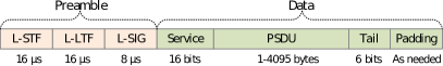
The data structure that the PHY receives from MAC in IEEE 802.11p is termed as Protocol Packet Data Unit (PPDU) (or PSDU) that is made up of three components - preamble and data fields as shown in Figure 1. In the preamble, Short Training Field (STF) is used for packet detection, coarse frequency correction and automatic gain control. Long Training Field (LTF) is used for fine frequency correction, fine symbol timing offset correction and pilot based channel estimation. The Signal (SIG) field contains packet information for the received configuration such as Modulation-Coding Scheme (MCS) used and the PLCP Service Data Unit (PSDU) length. The service field consists of 16 zeros to initialize the data scrambler. PSDU contains the actual user data. Tail bits are used to terminate the convolutional code and the padding bits are added to ensure an integer number of symbols.
For actual transmission, OFDM is used with a total of 64 Sub-Carriers (SCs). Out of these 64 SCs, 52 are used for carrying data and pilot symbols and the remaining 12 are null SCs that carry no data. The null SCs occupy the central 11 SCs and the 0th SC. The pilot symbols occupy 4 SCs with indices 7, 10, 44 and 58. The remaining 48 SCs are used for data [14]. The actual length of data depends on the choice of MCS with the supported schemes outlined in Table I
| MCS | Modulation | Coding Rate |
|
|
||||
|---|---|---|---|---|---|---|---|---|
| 0 | BPSK | 1/2 | 48 (24 data bits) | 3 | ||||
| 1 | BPSK | 3/4 | 48 (36 data bits) | 4.5 | ||||
| 2 | QPSK | 1/2 | 96 (48 data bits) | 6 | ||||
| 3 | QPSK | 3/4 | 96 (72 data bits) | 9 | ||||
| 4 | 16QAM | 1/2 | 192 (96 data bits) | 12 | ||||
| 5 | 16QAM | 3/4 | 192 (144 data bits) | 18 | ||||
| 6 | 64QAM | 2/3 | 288 (192 data bits) | 24 | ||||
| 7 | 64QAM | 3/4 | 299 (216 data bits) | 27 |
II-B Cellular-V2X (C-V2X)
3GPP’s Release.12 standard included significant changes to the legacy LTE architecture by introducing the concept of direct D2D communications. Known collectively as Proximity Services (ProSe), this mode enables UEs that are in close proximity to directly establish a communication link (via a PC5 interface) between themselves instead of relying on the network infrastructure. Cellular resources in the Uplink (UL) are used for ProSe services mainly because of two reasons: 1) UL transmissions are sporadic compared to Downlink (DL) where the eNB has always something to transmit and 2) Due to the low transmission power and geographical separation of the UEs, interference is also less in the UL band.
V2X Enhancements
The LTE D2D standard is proposed keeping in mind the emergency public communications and proximity based advertisements using conventional UEs, i.e., smartphones, whose positions are usually assumed to be semi-static. However, V2X links are highly dynamic with higher channel uncertainties. Secondly, the node density is also comparatively higher especially in urban areas. Hence, to this end 3GPP introduced few fundamental modifications to the PC5 interface (sidelink interface) to meet the more stringent latency and reliability requirements associated with the vehicular use cases. They are
-
i.
Using additional Demodulation Reference Symbols (DMRSs) (4 instead of 3) to handle the higher Doppler corresponding to relative speeds of up to 500 km/h and at high frequency (5.9 GHz ITS band)
-
ii.
Using a new resource scheduling assignment of UL resources where the control data and the shared data are transmitted in a single subframe over adjacent Physical Resource Blocks (PRBs). More information about the concept of Resource Pools (RPs) can be found in the next section.
-
iii.
For out of coverage resource scheduling assignment, a sensing with semi-persistent transmission based mechanism was introduced. Since V2V traffic is mostly periodic in nature, this property is utilized to sense congestion on a resource and estimate future congestion on that resource.
Resource Pool (RP)
In contrast to IEEE 802.11p that use the entire available bandwidth (10 MHz) for each packet transmission, the sidelink transmissions are scheduled to operate side by side with the UL transmissions and only in a subset of SCs. Hence, new measures for resource allocation and transmission scheduling are required. This is achieved by means of RPs; a set of resources assigned to the SideLink (SL) operation. It consists of a set of sub-frames and resource blocks within. The physical resources (sub-frames and resource blocks) associated with a given pool are partitioned into a sequence of repeating hyperframes known as Physical Sidelink Shared Channel (PSSCH) periods, also referred to as the Scheduling Assignment (SA) period or Sidelink Control (SC) period. Within a PSSCH period there are separate sub-frame pools and resource block pools for control and data. The Physical Sidelink Control Channel (PSCCH) carries Sidelink Control Message (SCI) messages, which describe the dynamic transmission properties of the PSSCH that follow it. The receiving UE searches all configured PSSCH resource pools for SCI transmissions of interest to it.
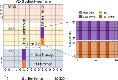
Figure 2 illustrates an example sidelink hyperframe for a bandwidth of 10 MHz and a PSSCH period of 40 ms. Within a PSSCH period, the actual sidelink transmissions can be found on any two subframes (for first transmission and retransmission) given by the subframe bitmap. For the considered bandwidth of 10 MHz, there are 50 PRBs that are divided into 10 sub-pools each consisting of 5 contiguous PRBs. A UE can use one or multiple sub-pools for transmission as specified by higher layer messages. For retransmission (1 blind retransmission is supported by default), the UE can use the same set of sub-pools as the first transmission and use different sub-pools for the subsequent retransmission. In our example, the UE uses RP 1 for the first transmission and RP 2 for the retransmission.
The SCI message always spans 2 PRBs which is succeeded by the data message. For the given example, a data message spanning over 3 PRBs is assumed. The content of each message is also illustrated in Figure 2. In line with the LTE specification, each PRB consists of 12 SCs in the frequency domain and 14 OFDM symbols in the time domain. Symbols 2, 5, 8 and 11 are used for transmitting DMRS that are used for frequency correction and channel estimation. The remaining 10 symbols are used to carry the actual data.
| MCS Index | Modulation |
|
|
||||
|---|---|---|---|---|---|---|---|
| 0 | QPSK | 1320 | 0.127 | ||||
| 1 | QPSK | 1736 | 0.167 | ||||
| 2 | QPSK | 2152 | 0.207 | ||||
| 3 | QPSK | 2792 | 0.269 | ||||
| 4 | QPSK | 3496 | 0.337 | ||||
| 5 | QPSK | 4264 | 0.411 | ||||
| 6 | QPSK | 4968 | 0.479 | ||||
| 7 | QPSK | 5992 | 0.577 | ||||
| 8 | QPSK | 6712 | 0.647 | ||||
| 9 | QPSK | 7480 | 0.721 | ||||
| 10 | QPSK | 8504 | 0.820 | ||||
| 11 | 16QAM | 8504 | 0.410 | ||||
| 12 | 16QAM | 9528 | 0.459 | ||||
| 13 | 16QAM | 11064 | 0.533 | ||||
| 14 | 16QAM | 12216 | 0.589 | ||||
| 15 | 16QAM | 13536 | 0.652 | ||||
| 16 | 16QAM | 14688 | 0.708 | ||||
| 17 | 16QAM | 15840 | 0.763 | ||||
| 18 | 16QAM | 17568 | 0.857 | ||||
| 19 | 16QAM | 19080 | 0.920 | ||||
| 20 | 16QAM | 20616 | 0.994 |
The PHY layer of the C-V2X is same as the LTE uplink and uses Single Carrier Frequency Division Multiple Access (SC-FDMA) as the access technique. SC-FDMA has lower Peak to Average Power Ratio (PAPR) when compared to OFDM while at the same time combining the advantages of multipath interference resilience and flexible sub-carrier frequency allocation that OFDM provides. The individual SCs are modulating using one of the three modulation schemes namely - QPSK, 16-QAM and 64-QAM. Table II outlines the different MCS schemes for a bandwidth of 10 MHz [15].111Before SC-FDMA modulation, the last symbol is set to 0 in accordance with 3GPP specification. Therefore the total useful symbols per subframe becomes 9. These values are used for calculating the effective coding rate.
III Link level Simulation Methodology
For link level simulation, the complete transmit and receive operations needs to be built. This section outlines the baseband processing for both IEEE 802.11p and C-V2X
III-A IEEE 802.11p Baseband Processing
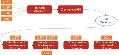
The simulation pipeline for IEEE 802.11p is outlined in 3. The LTF, STF and SIG symbols are concatenated together to form the preamble. The user data is convolutionally encoded and mapped to symbols corresponding to the selected MCS. Finally, the preamble and the data symbols are concatenated together and OFDM modulated to create the time-domain waveform. The waveform is passed through a fading channel and Additive White Gaussian Noise (AWGN) noise is added to it to get the received waveform. The following operations are performed sequentially on the received waveform to decode the data
-
i.
Packet detection, estimation of coarse packet offset and coarse frequency correction using the STF
-
ii.
Fine packet offset estimation, fine frequency offset correction and fine symbol timing offset correction using the complete preamble
-
iii.
Demodulation of LTF and channel estimation using the pilot symbols
-
iv.
The constructed channel coefficient matrix is used to demodulate, equalize and decode the user data
III-B C-V2X Baseband Processing
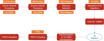
Figure 4 shows the baseband processing pipeline for C-V2X. As it can be seen, control message and data message processing is done separately and these symbols are sequentially added to the time-frequency resource grid.
III-B1 Control Channel Processing
The first step is control channel processing is to create and encode the SCI message. For V2X transmission a ’Format 1’ SCI message is generated that consists of information such as the MCS, Resource Indication Value (RIV), the time gap between initial transmission and retransmission and the retransmission index (0 in case of initial transmission and 2 in case of first retransmission). The generated binary message is encoded using a convolutional encoder followed by rate matching, interleaving and a 16-bit CRC is attached to the encoded message. The 16-bit CRC is then converted into a decimal and this value is referred to as V2X Scrambling Identity (NXID). It is used as the initialization value for generating the gold sequence which is in turn used for scrambling the user data. This effectively means that the receiver would be able to decode the data message if and only if it has decoded the SCI message successfully and recovered the 16 bit CRC remainder.
After generating the binary code word, next processing steps involve PSCCH-specific scrambling, QPSK modulation and SC-FDMA transform precoding to generate symbols. The generated PSCCH symbols (240) and are cyclic shifted with a random value chosen from set [0, 3, 6, 9] in order to reduce the effect of interference. Finally, 4 DMRS symbols are generated and mapped to the remaining 4 time domain symbols ([2,5,8,11]).
III-B2 Shared Channel Processing
Sidelink Shared Channel (SL-SCH) processing includes type-24A CRC calculation, code block segmentation (including type-24B CRC attachment, if present), turbo encoding, rate matching with redundancy version (RV), code block concatenation, and interleaving. The generated codeword is then scrambled, modulated using either QPSK or 16QAM. This is followed by Discrete Fourier Transformation (DFT) by means of transform precoding in order to generate the data symbols. Similar to the control channel, DMRS symbols are added and transmitted alongside the data symbols in a PSSCH subframe.
All the symbols are then mapped to the sidelink resource grid followed by SC-FDMA modulation to create the time domain waveform. The generated time domain waveform is then filtered through a channel and AWGN noise is added to it.
III-B3 Receiver Operations
For each resource pool as configured in the resource pool selection, the receiver tries to perform a blind decoding of the control information by iterating over all possible cyclic shift values. For each selected cyclic shift, the receiver first corrects the frequency offset, demodulates the SC-FDMA time domain symbols to recover the resource grid. This is followed by channel estimation using a cubic interpolation over a pre-specified time and frequency window. The effect of the channel is equalized by dividing the received grid with that of the estimated channel grid. After this, the control symbols are extracted and are then decoded (by performing the inverse operations) to recover the SCI message. If the SCI decoding is successful, then the receiver converts the 16 bit CRC checksum into a decimal NXID is used to proceed with decoding the data message. If the decoding is not successful, it means that the shared data is also discarded.
After decoding the SCI message and recovering the NXID, the receiver proceeds with decoding the data. Similar operations (channel estimation, equalization and turbo decoding) are performed to recover the data block.
IV Performance Comparison over Fading Channels
In order to have a fair comparison between IEEE 802.11p and C-V2X, some baseline assumptions are required to be made. A packet size of 300 bytes (2400 bits) is assumed which seems to be an acceptable value for safety messages [16, 17, 18]. For fairness, only one transmission was assumed even though C-V2X supports one blind retansmission by default. Since, we limit our analysis to safety messages, we only consider lower order modulation schemes, i.e., QPSK with coding rates 1/2 and 3/4. For IEEE 802.11p, this corresponds to MCS 2 and 3 respectively. In case of C-V2X which is based on LTE, it is not possible to set the packet size to exactly 300 bytes since the MCS has to be selected from a list of predefined values based on the available PRBs. Moreover, the coding rate is always a bit on the lower/higher side due to rate matching and the tail bits added to the turbo encoder. Hence, the configurations in III are used for C-V2X in order to keep the coding rates as close to that of ITS-G5 and not violating the intended packet size too much.
| MCS Scheme | MCS Index | TBS | PRBs |
|
||
|---|---|---|---|---|---|---|
| QPSK 1/2 | 7 | 2472 | 20 | 0.515 | ||
| QPSK 3/4 | 10 | 2664 | 15 | 0.74 |
IV-A ITU Channel Models
ITU [10] specifies three different test environments: Indoor office, outdoor-to-indoor pedestrian and vehicular-high antenna. For the vehicular test environment, a low (A) and medium (B) delay spreads have been defined with 6 channel taps and an RMS delay spread of 370 ns and 4000 ns respectively. The Channel A was extended with additional taps to support higher bandwidths. The path delays and gains of these models are outlined in Table IV
| Model | Path Delays (ns) | Path Gains (dB) |
|---|---|---|
| ITU - VA | [0, 310, 710, 1090, 1730, 2510] | [0, -1, -0, -10, -15, -20] |
| ITU - VB | [0, 300, 8900, 12900, 17100, 20000] | [-2.5, 0, -12.8, -10, -25.2, -16] |
| ITU-EVA | [0, 30, 150, 310, 370, 710, 1090, 1730, 2510] | [0, -1.5, -1.4, -3.6, -0.6, -9.1, -7, -12, -16.9] |
IV-B IEEE Tiger Team Channel Models
During 2007-2010, a total of 35 field trial campaigns were conducted on public roads in US, Germany, Austria, Italy and Australia totalling over 1100 kilometres [11]. These campaigns demonstrated different V2I and V2V scenarios such as Intersection Movement Assist (IMA), Do Not Pass Warning (DNPW), EEBL and driving across an Road Side Unit (RSU). For each test location, multiple repetitions of a scenario were run transmitting messages at an aggregate of 400 packets/s. For the purpose of measurements, vehicles mounted with Cohda wireless MKI IEEE 802.11p DSRC units with single antenna were used. The channel sounding data captured during the field trials were analysed to obtain delay and Doppler spread characteristics. Using these statistics, a total of 5 channel models were proposed for different scenarios and are outlined in Table V.
| Scenario | Path Delays (ns) | Path Gains (dB) | Doppler Shift (Hz) | ||
|---|---|---|---|---|---|
| Rural LOS | [0, 83, 183] | [0, -14, -17] | [0, 492, -295] | ||
|
[0, 117, 183, 333] | [0, -8, -10, -15] | [0, 236, -157, 492] | ||
| Urban NLOS | [0, 267, 400, 533] | [0, -3, -5, -10] | [0, 295, -98, 591] | ||
| Highway LOS | [0, 100, 167, 500] | [0, -10, -15, -20] | [0, 689, -492, 886] | ||
| Highway NLOS | [0, 200, 433, 700] | [0, -2, -5 -7] | [0, 689, -492, 886] |
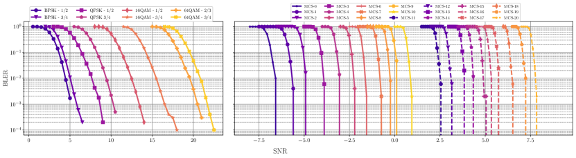
Figure 5 shows the BLER performance over AWGN channels for both IEEE 802.11p and C-V2X. It can be seen that for the considered MCS schemes, i.e., QPSK 1/2 and 3/4, C-V2X provides a performance gain of almost close to 10 dB. This is because of the use of turbo encoder compared to a convolutional encoder that is used in IEEE 802.11p. Secondly, due to the presence of a higher number of DMRS symbols in C-V2X when compared to IEEE 802.11p, the noise is also estimated better resulting in more robust channel equalization.
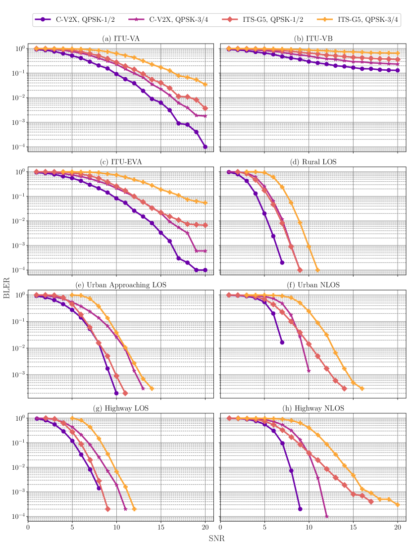
Figure 6 shows the performance comparison over fading channels as outlined in Tables IV and V. For the case of ITU channel models (a-c), it can be clearly seen that C-V2X exhibits a gain of almost 4-6 dB. The gain is more pronounced for coding rate 3/4 than 1/2. The performance is almost similar for both ITU-VA and ITU-EVA channels. This is expected since ITU-EVA is just an extension of ITU-VA channel model with more paths. However, both the technologies perform very poorly for ITU-VB. This is due to the very large delay spread (20000 ns) that is way greater than the Cyclic Prefix (CP) length and thereby causing high inter-symbol interference. However, it can be noted that C-V2X still performs a bit better than IEEE 802.11p.
Figures 6 (d-h) show the performance comparison for Tiger team channel models. It can be seen that C-V2X, in general fares better than IEEE 802.11p for all scenarios with gains ranging from 0-5 dB with the exception of model (e) where the performance of both the technologies is almost identical. The performance of IEEE 802.11p QPSK 1/2 is similar to that of C-V2X QPSK 3/4 for model (d). It can also be seen that C-V2X performs better for NLOS scenarios, especially for scenario (h) where the vehicles speeds are higher. This shows that C-V2X is better equipped to handle high speed scenarios which in turn is due to the higher number of DMRS symbols thereby resulting in better channel estimation performance.
V Conclusions & Future Work
In this work, we evaluated the link level performance of the two candidate technologies for V2X communication, namely IEEE 802.11p and C-V2X for different channel models. The considered channel models include those from the ITU (VA, VB and EVA) and the DSRC channel models from the IEEE Tiger team that were developed after extensive field trials. Two MCS schemes - QPSK 1/2 and QPSK 3/4 were considered for the evaluation for a packet size of 300 bytes. The results show that C-V2X outperforms IEEE 802.11p for almost all of the considered channel models with a gain ranging from 0-5 dB. Moreover, it is also clear from the results that C-V2X performs better at higher vehicle speeds. This better performance of C-V2X can be attributed to the use of turbo encoder and the better channel estimation mechanism that makes use of a higher number of DMRS symbols.
Acknowledgements
Part of this work has been performed in the framework of the BMVI project Connected Vehicle (V2X) of Tomorrow (ConVeX). The authors would like to acknowledge the contributions of their colleagues, although the views expressed are those of the authors and do not necessarily represent the project.
References
- [1] I. Tan, W. Tang, K. Laberteaux, and A. Bahai, “Measurement and Analysis of Wireless Channel Impairments in DSRC Vehicular Communications,” in 2008 IEEE International Conference on Communications. IEEE, 2008, pp. 4882–4888.
- [2] J. A. Fernandez, K. Borries, L. Cheng, B. V. Vijaya Kumar, D. D. Stancil, and F. Bai, “Performance of the 802.11p physical layer in vehicle-to-vehicle environments,” IEEE Transactions on Vehicular Technology, 2012.
- [3] A. Paier, D. Faetani, and C. F. Mecklenbrauker, “Performance evaluation of IEEE 802.11p physical layer infrastructure-to-vehicle real-world measurements,” in 2010 3rd International Symposium on Applied Sciences in Biomedical and Communication Technologies (ISABEL 2010). IEEE, nov 2010, pp. 1–5.
- [4] Z. H. Mir and F. Filali, “On the Performance Comparison between IEEE 802.11p and LTE-Based Vehicular Networks,” in 2014 IEEE 79th Vehicular Technology Conference (VTC Spring). IEEE, may 2014, pp. 1–5.
- [5] A. Moller, J. Nuckelt, D. M. Rose, and T. Kurner, “Physical Layer Performance Comparison of LTE and IEEE 802.11p for Vehicular Communication in an Urban NLOS Scenario,” in 2014 IEEE 80th Vehicular Technology Conference (VTC2014-Fall). IEEE, sep 2014, pp. 1–5.
- [6] F. J. Cintron, “Performance evaluation of LTE device-to-device out-of-coverage communication with frequency hopping resource scheduling,” National Institute of Standards and Technology, Gaithersburg, MD, Tech. Rep., jul 2018.
- [7] J. Hu, S. Chen, L. Zhao, Y. Li, J. Fang, B. Li, and Y. Shi, “Link level performance comparison between LTE V2X and DSRC,” Journal of Communications and Information Networks, vol. 2, no. 2, pp. 101–112, jun 2017.
- [8] P. Kyösti, J. Meinilä, L. Hentilä, X. Zhao, T. Jämsä, C. Schneider, M. Narandzic, M. Milojevic, A. Hong, J. Ylitalo, V.-M. Holappa, M. Alatossava, R. J. C. Bultitude, Y. L. C. D. Jong, T. Rautiainen, J. Ebitg, Meinilä, X. Ebitg, Z. Zhao, M. Uoulu, Alatossava, V.-M. Uoulu, Holappa, R. Crc, Bultitude, and C. Y. D. Jong, “WINNER II Channel Models Part I Channel Models.”
- [9] V. Mannoni, V. Berg, S. Sesia, and E. Perraud, “A Comparison of the V2X Communication Systems: ITS-G5 and C-V2X,” in 2019 IEEE 89th Vehicular Technology Conference (VTC2019-Spring). IEEE, apr 2019, pp. 1–5.
- [10] IEEE, “Guidelines for evaluation of Radio Transmission Technologies for IMT-2000 (Question ITU-R 39/8) (1997),” Tech. Rep.
- [11] P. Alexander, D. Haley, and A. Grant, “Cooperative Intelligent Transport Systems: 5.9-GHz Field Trials,” Proceedings of the IEEE, vol. 99, no. 7, pp. 1213–1235, jul 2011.
- [12] IEEE Computer Society. LAN/MAN Standards Committee., Institute of Electrical and Electronics Engineers., and IEEE-SA Standards Board., IEEE standard for information technology : telecommunications and information exchange between systems : local and metropolitan area networks–specific requirements. Part 11, Wireless LAN medium access control (MAC) and physical layer (PHY) specifications. Institute of Electrical and Electronics Engineers, 2012. [Online]. Available: https://ieeexplore.ieee.org/document/6178212
- [13] A. Festag, “Cooperative intelligent transport systems standards in Europe,” IEEE Communications Magazine, 2014.
- [14] A. M. Abdelgader and W. Lenan, “The physical layer of the IEEE 802. 11p WAVE communication standard: The specifications and challenges,” in World Congress on Engineering and Computer Science 2014, WCECS 2014, At San Francisco, USA, vol. 2, 2014.
- [15] TSGR, “TS 136 211 - V15.3.0 - LTE; Evolved Universal Terrestrial Radio Access (E-UTRA); Physical channels and modulation (3GPP TS 36.211 version 15.3.0 Release 15),” Tech. Rep., 2018.
- [16] V. D. Khairnar and K. Kotecha, “Performance of Vehicle-to-Vehicle Communication using IEEE 802.11p in Vehicular Ad-hoc Network Environment,” International Journal of Network Security & Its Applications, vol. 5, no. 2, pp. 143–170, mar 2013.
- [17] C. Consortium, “Survey on ITS-G5 CAM statistics,” Car2Car Consortium, Tech. Rep., 2018.
- [18] X. Ma, X. Chen, and H. H. Refai, “Performance and Reliability of DSRC Vehicular Safety Communication: A Formal Analysis,” EURASIP Journal on Wireless Communications and Networking, vol. 2009, no. 1, p. 969164, dec 2009.