OTSLM Toolbox for Structured Light Methods
Abstract
We present a new Matlab toolbox for generating phase and amplitude patterns for digital micro-mirror device (DMD) and liquid crystal (LC) based spatial light modulators (SLMs). This toolbox consists of a collection of algorithms commonly used for generating patterns for these devices with a focus on optical tweezers beam shaping applications. In addition to the algorithms provided, we have put together a range of user interfaces for simplifying the use of these patterns. The toolbox currently has functionality to generate patterns which can be saved as a image or displayed on a device/screen using the supplied interface. We have only implemented interfaces for the devices our group currently uses but we believe that extending the code we provide to other devices should be fairly straightforward. The range of algorithms included in the toolbox is not exhaustive. However, by making the toolbox open sources and available on GitHub we hope that other researchers working with these devices will contribute their patterns/algorithms to the toolbox.
keywords:
Optical tweezers , Structured Light Methods , Digital Micro-mirror device , Spatial Light Modulator , Computer controlled hologramsPre-print of:
I. Lenton, et al., OTSLM toolbox for Structured Light Methods, Computer Physics Communications, 2020, 107199, https://doi.org/10.1016/j.cpc.2020.107199.
© 2019. This manuscript version is made available under the CC-BY-NC-ND 4.0
license http://creativecommons.org/licenses/by-nc-nd/4.0/.
PROGRAM SUMMARY
Program Title: OTSLM Toolbox for Structured Light Methods
Licensing provisions: GPLv3
Programming language: Matlab
Nature of problem:
There are many algorithms for generating computer
controlled holograms however the code and descriptions for these algorithms
is often provided as supplementary material to research publications which
use these methods, and in some cases only the description is provided without code
to reproduce the pattern.
Furthermore, implementation of these algorithms can be a time consuming task.
Even for simple patterns with simple analytical expressions for the far-field
phase or amplitude, such as the Laguerre-Gaussian and Hermite-Gaussian beams,
time is often wasted by researchers having to re-implement and test these patterns.
Existing libraries for generation of SLM patterns focus on specific tasks,
methods of pattern generation, or target specific hardware.
These libraries are not general purpose or easily modifiable for
general use by researchers working with computer controlled holograms in
fields such as beam shaping and optical tweezers.
Solution method:
We have assembled a toolbox containing many
methods commonly used with these devices. The number of methods available
makes assembling a complete toolbox impossible, instead we have
focused on putting together a general collection of methods, in the form of
an open source toolbox, with the hope that other researchers
will contribute patterns/algorithms they use.
The toolbox currently includes a range of simple and iterative methods
for beam shaping and steering as well as some of the methods our group currently
uses for SLM control, calibration, imaging and optical tweezers beam shaping.
To make the tools we have developed easy to use, we have tried to maintain
a consistent well documented interface to each of the functions and provided
graphical user interfaces to many of the simpler functions enabling code-free
pattern generation.
Additional comments:
Some of the features require the Optical Tweezers Toolbox [1], in particular, the
non-paraxial beam visualisation and optimisation routines.
Certain functions require components from other Matlab packages such as the
image acquisition toolbox, these can be licensed and installed from Mathworks.
There is also interest from the authors in providing a Python version that
requires no proprietary components depending on interest from the community.
A public repository for the toolbox is available on GitHub [2].
References
- [1] Optical Tweezers Toolbox (Version 1), https://github.com/ilent2/ott, (2019).
- [2] OTSLM, https://github.com/ilent2/otslm, (2019).
1 Introduction
Beam shaping using computer controlled spatial light modulators is useful in many fields with applications in imaging, optical tweezers, and optical fabrication. In optical tweezers, beam shaping is used to generate the beams used to optically confine the particles under study [1], construct elaborate imaging systems [2, 3], and for fabricating probes and structures that can be optically trapped. A modern optical tweezers system typically consists of a laser, a system for shaping the laser beam, a high numerical aperture objective, the sample, a condenser and the imaging/detection system. Such a system enables numerous studies to be conducted in highly versatile fields including biology, physics and engineering [4, 2]. Optical tweezers are also being used in quantum opto-mechanics in studies concerned with borderline between classical and quantum physics. In all of these applications beam shaping is essential in enabling desired studies. Despite the extensive use of computer controlled holograms in the field of optical tweezers, there is limited availability of code for generating the types of patterns typically used for these applications. To address this issue, we have put together a toolbox of functions useful for optical tweezers researchers, however we believe that the toolbox will be more broadly useful to other fields involving beam shaping and structured light with theses devices.
Existing libraries for generation of SLM patterns focus on specific tasks or methods of pattern generation. Tools for optical tweezers include red-tweezers [5], written in LabView for generating patterns using computer graphics cards; and HoloTrap [6], written in Java for real time generation of binary mask holograms. There are also tools for specific hardware, such as HOLOEYE SLM Pattern Generator [7], and tools with other intended applications such as llspy-slm for light sheet microscopy [8]. Some groups make available the code they use to demonstrate a particular algorithm or result for a paper, such as [9], however these published codes are sometimes difficult to find/access, are rarely user friendly and often need additional modification for integration into an optical tweezers system.
The toolbox we have developed [10], does not focus on a particular device and includes patterns of interest to the broad optical trapping community and hopefully the wider beam shaping community. At this stage we include the patterns that we have used in our recent and ongoing experiments. To make the toolbox easy to use, we have provided both a Matlab programmers interface and a graphical user interface allowing the tools to be used without the need to write code. We have tried to ensure that the toolbox follows a consistent documentation format and tried to keep the interfaces similar between similar functions to make it easier to move between different components in the toolbox. By making the toolbox open source and available on GitHub, it is hoped that the wider computer controlled hologram community will contribute their codes/methods for generating patterns they use and make them more accessible. It is our hope that this will lead to a curated toolbox of functions for beam shaping with a consistent user interface and documentation that will be beneficial to the community.
2 Background
2.1 Device overview and operation
There are a variety of systems used for beam shaping, but among the most common are amplitude and phase spatial light modulators, such as the digital micro-mirror device (binary amplitude SLM, or DMD) or liquid crystal (phase SLM) [11, 12]111It is important to note that, in the literature, the term SLM may be used ambiguously to refer to either phase-only devices or any device capable of modulating the beam wave-front. In this article we use SLM to refer to any device capable of modulating the beam phase and/or amplitude. These highly configurable devices can be controlled using a variety of different interfaces but a common method is to connect them as an additional screen on the lab computer. The image displayed on the screen corresponds to the amplitude or phase pattern displayed on the device. There are numerous guides for setting up one of these devices in an optical tweezers system [13, 14], and many of these guides describe generating SLM patterns for beam shaping but they do not provide easy to use codes. In some cases [14], tasks such as simultaneous phase/amplitude modulation are not described.
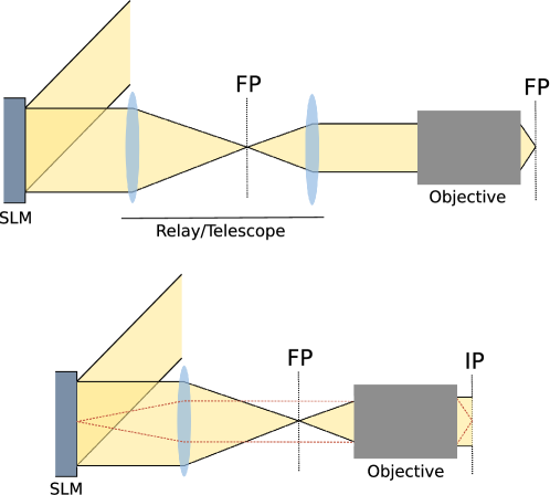
For creating structured optical tweezers beams, the incident beam either reflects or passes through the device before being focused by a microscope objective. The position of the device with respect to the microscope objective changes how the device controls the beam. Two commonly used configurations are shown in figure 1. Phase based devices are typically imaged onto the back focal plane of the objective to allow spatial control of the generated pattern at the focal plane. When the device is imaged onto the back focal plane, the focal plane corresponds to a conjugate plane of the SLM, i.e. the image at the objective focal plane corresponds to the spatial frequency spectrum of the image on the device. Amplitude based devices can be imaged onto the back plane, producing a Fourier image at the focal plane [15, 16], or imaged directly to the focal plane [17]. When imaged directly, the beam generated by amplitude based devices is somewhat intuitive, since the pattern on the SLM corresponds to the pattern at the focal plane with resolution limited by aberrations and the transfer function of the system. Intermediate planes between the imaging and conjugate planes can be thought of as a mixture of the image and conjugate planes. In addition to the two configurations described here, other systems can involve placing the SLM in a Fresnel plane or other plane [18] or omitting the lens entirely [19]. It is also possible to use multiple devices or multiple passes of the same device to achieve greater control over both amplitude and phase [20].
Determining the appropriate pattern to place on the device to generate the desired beam depends on a number of factors including the device position and incident illumination. If the device is positioned in the conjugate plane and uniformly illuminated, the required device pattern is simply the far-field complex amplitude of the desired beam. For simple beam shapes, such as beams translated to different positions, the required patterns can be easily determined and correspond to patterns for diffraction gratings and lenses. Once the complex amplitude function for the desired beam is determined, the phase or amplitude pattern can be calculated and converted to a device specific image with values corresponding to the phase/amplitude range of the device. For non-uniform incident illumination, pattern generation becomes more complex: the beam phase and amplitude distribution and the phase uniformity of the device is needed, which must then be encoded in the generated pattern. More complex patterns, where the far-field phase or intensity is not intuitive, can be generated using iterative algorithms such as the popular Gerchberg–Saxton algorithm [21].
When using one of these devices there are several additional considerations arising from the physical properties of the device that may impact the generated patterns. For example, for phase-only SLMs, such as liquid crystal type devices, the orientation of the liquid crystals is controlled by applying a voltage to align the crystals in a particular direction. The change in orientation of the liquid crystals results in a change in phase and if the crystals are birefringent, a change in polarisation of light passing through the corresponding region of the device will occur (making the device not purely phase-only). Part of the setup for one of these devices often involves calibrating the device voltage to corresponding phase/polarisation values. The physical process involved in changing the phase/polarisation of the light may not be perfectly efficient, this leads to effects such as pixel blurring and non-diffracted light in the resulting beam.
2.2 Simple patterns
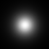
For optical tweezers experiments, there are a range of simple patterns that are often used for basic beam steering and control of trapped particles. The most common optical tweezers beamis a Gaussian beam, which can be described in the far-field of the focus by a scalar amplitude function with constant phase and a Gaussian profile,
| (1) |
with only a single parameter, , the width of the beam.
We can focus or deflect a beam by applying a lens or linear phase grating to the beam. To first order approximation the phase profiles for a lens and grating are given by
| (2) | |||||
| (3) |
where is the radius of curvature for the lens, is the distance displaced and is the direction of the displacement. By applying these phase shifts to our Gaussian beam, we are able to move the focus of the beam in the axial direction and in the transverse direction . These formulas can be applied to a beam by multiplying the beam by the corresponding complex field amplitude
| (4) |
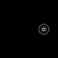
where is the imaginary unit and is the optical wavenumber. Examples of these diffraction gratings are shown in figure 2(a-c).
a) 
 e)
e) 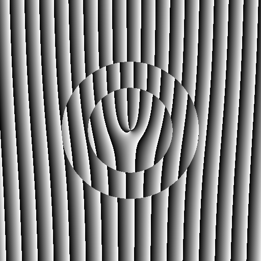
 b)
b) 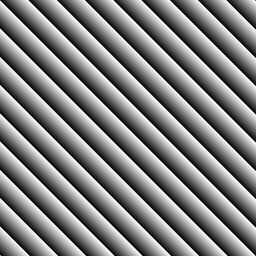
 f)
f) 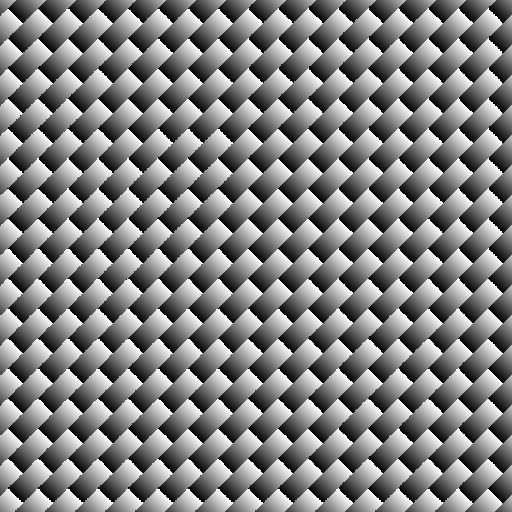
 c)
c) 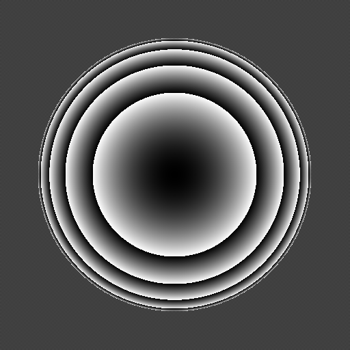
 g)
g) 
 d)
d) 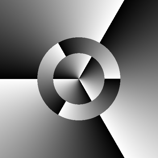
 h)
h) 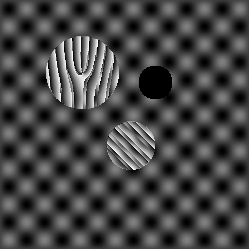
Orbital angular momentum can be added to a beam by adding a azimuthal phase gradient to the pattern. The Laguerre-Gaussian modes are Gaussian beam modes which include a azimuthal phase component, this additional phase is described by
| (5) |
Figure 2(d-e) show LG modes with both azimuthal phase and radial phase. More complex patterns can be generated for Hermite-Gauss, Ince-Gauss and other types of beams.
2.3 Combining multiple patterns
It may be desirable to combine a set of patterns together to create multiple beams. There are multiple methods of achieving this including the random mask method and superposition of prisms and lenses. The random mask method involves randomly choosing pixels from each pattern and combining them into a single image. To combine a set of patterns using the random mask method, the pixels in the combined pattern are given by
| (6) |
where refers to the individual pixels that make up the pattern and is chosen randomly for each pixel. By changing the frequency at which a particular pattern is chosen, the amplitude of the individual patterns can be controlled. The efficiency for this method for uniform beam amplitudes scales inversely with the number of traps, providing lower efficiency compared to other methods.
The superposition of prisms and lenses algorithm involves superimposing the complex amplitude patterns of each pattern and calculating the phase angle
| (7) |
The additional weighting terms, , are used to control the amplitude of each trap, while the phase offset terms, can be used to introduce a random phase offset which may improve the performance of the method [22]. For further reading see [23]. An example of superposition is shown in figure 2(f).
2.4 Simulating tightly focused beams
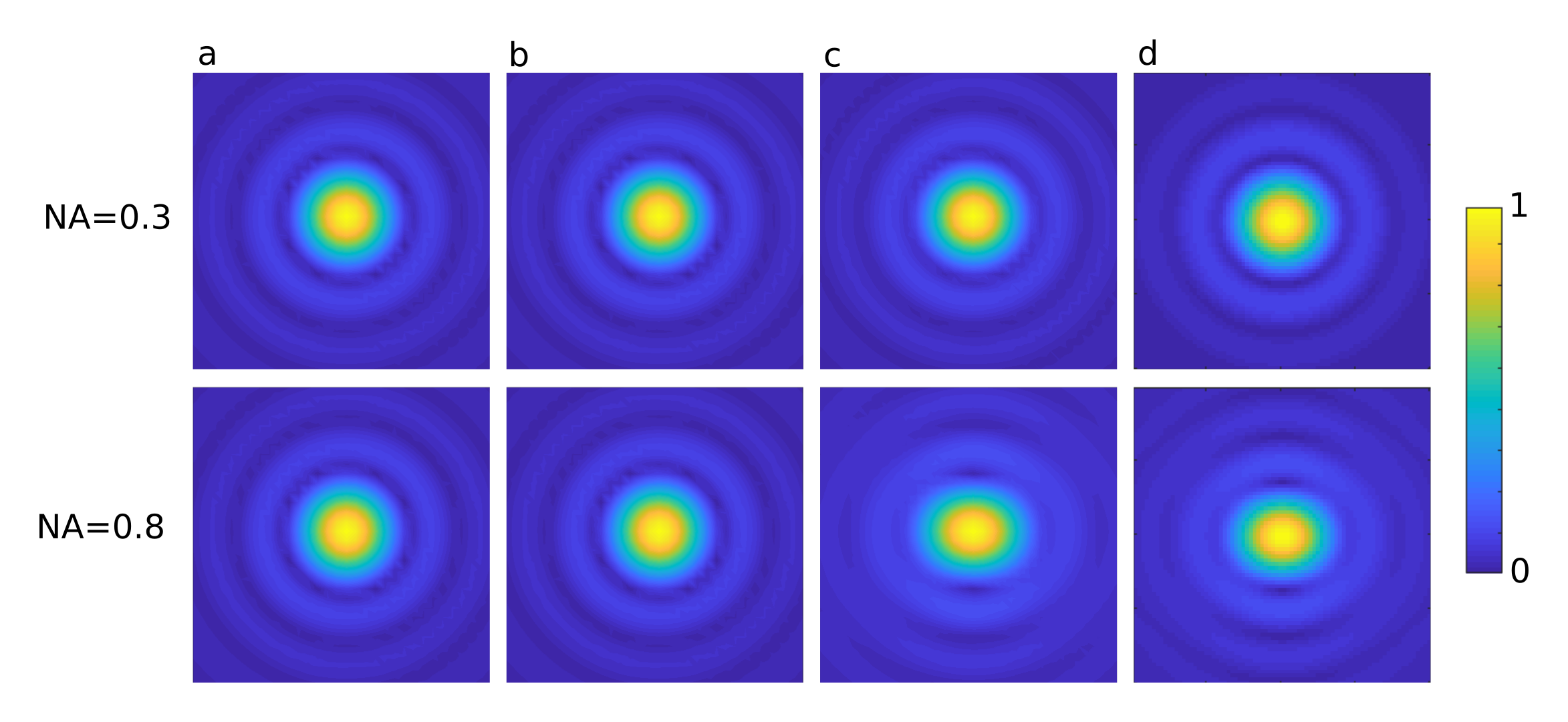
Optical tweezers often use tightly focused beams created using high numerical aperture (NA) objectives (NA 0.7–1). These beams are often not solutions to the scalar Helmholtz equation. Full modelling often requires higher order approximations or solutions to the vector Helmholtz equation [24, 25]. The simulations in figure 2 assumed the beams to be paraxial (scalar) and do not account for changes to the beam polarisation due to focusing. For low numerical aperture simulations, this can produce reasonably accurate results. However, for beams used in optical tweezers it can be necessary to include polarisation effects. Figure 3 shows a comparison of four different beam simulation methods currently implemented in OTSLM [26, 27, 28, 29]. For weakly focused beams (NA=0.3) there is very little visible difference between the different methods. The scalar fast Fourier transform (FFT) methods, figure 3(a–b), do not include the polarisation of the incident beam and produces a spot which can differ significantly from the experimentally realised beams. In order to model polarisation effects in highly focused beams, one simple method is to repeat the FFT method for each polarisation component. Further adaptations can be added to account for spherical aberration due to the lenses finite dimensions and the projection of the paraxial polarisation components onto the hemisphere of the lens [28].
2.5 Simultaneous amplitude & phase control
In order to generate arbitrary beams both the amplitude and phase of the wave-front need to be controlled. Many liquid crystal type SLMs can be configured so that they control the phase and amplitude of the reflected light, however the phase and amplitude control is rarely independent [30]. Multiple devices can be combined, a device that only controls phase can be combined with a device that only controls amplitude: such as combing a liquid crystal type SLM with a DMD type SLM or two liquid crystal devices setup to modulate the phase and amplitude respectively [31]. If spatial resolution isn’t important, the same device can be used in a double pass configuration with the device being split into two halves one for controlling amplitude and the other for phase. It is also possible to use a spatial filter to combine adjacent pixels into a super-pixel that covers the complete amplitude/phase space [32, 33]. More complicated systems can even achieve phase, amplitude and polarisation control simultaneously with only a single DMD, half waveplates and beam displacers [34].
Without additional hardware or additional devices it is still possible to modify the SLM pattern to take advantage of the available amplitude/phase space. For phase only devices, one approach is to mix the desired phase pattern with a second phase pattern to give the phase pattern with both amplitude and phase information
| (8) |
where is a function between 0 and 1 which converts the amplitude pattern into a mixing ratio and is the other phase pattern to mix in. There are multiple choices for the function , the simplest situation is and to discard light into the zero-th order so the above equation becomes
| (9) |
For a comparison of different methods involving mixing multiple patterns to encode the amplitude on a phase-only device, see [35]. A similar procedure can be done for amplitude-only device [15].
2.6 Iterative algorithms
For generating more complex patterns there are a range of iterative algorithms that attempt to generate the incident phase or amplitude distribution for a desired target distribution for both phase only [36, 22, 37] and amplitude only devices [38]. One of the most popular and simple methods is the 2-D Gerchberg–Saxton (GS) algorithm [21], shown bellow:
-
1.
Generate initial guess at the SLM phase pattern:
-
2.
Calculate output for phase pattern:
-
3.
Multiply output phase by target amplitude:
-
4.
Calculate the complex amplitude required to generate :
-
5.
Calculate new guess from the phase of :
-
6.
Goto step 2 until converged
Proj is an operation to calculate the output field and Inv is the corresponding inverse operation, in the original GS these are the Fourier and inverse Fourier transforms. There are a range of modifications to this algorithm which achieve better uniformity or compatibility with amplitude only devices. An example of the GS algorithm is shown in figure 2(g). The 2-D Gerchberg–Saxton algorithm can be used to generate 3-D holograms by constraining the output to multiple planes in 3-D space or using a modified 3-D algorithm which allows optimisation with respect to a target volume [39, 40].
Other algorithms include direct search and simulated annealing which involves randomly changing pixel values to try and optimise the pattern [41, 42]; and gradient descent algorithms which attempt to directly optimise some fitness function [43].
It is also possible to optimise the amount of light scattered into particular directions without considering the light scattered to other locations in the far-field. This class of point-trap optimisation algorithms, or combination algorithms, effectively combines a set of phase patterns which describe the scattering in a particular direction [22]. In this description, we can write down a version of the Gerchberg–Saxton algorithm which doesn’t explicitly depend on the propagation method
| (10) |
where
| (11) |
are the pixel coordinates and is the best guess at the combined phase pattern. Starting with some initial guess, such as a random superposition of the phase patterns, the method rapidly converged. There are extensions to the Gerchberg–Saxton algorithm for point traps including an adaptive-adaptive algorithm and a weighted variant [22].
3 Toolbox overview
The Matlab toolbox is broken up into the following sub-packages:
-
1.
Simple patterns
otslm.simple -
2.
Iterative methods
otslm.iter -
3.
Pattern tools
otslm.tools -
4.
Utility functions
otslm.utils -
5.
Graphical user interface
otslm.ui
We also provide a directory with examples for various components of the toolbox. Simple patterns includes simple gratings, lenses and Hermite-Laguerre-Gauss beams. Iterative methods include the GS 2-D and 3-D algorithms for generating a pattern to satisfy a particular target light distribution. Pattern tools contains functions for combining patterns and functions for visualising the output of patterns. Also included are a number of utility functions that we use to display the patterns on the SLM devices with Matlab and the calibration functions. The user interface package contains the graphical user interface components.
All the pattern generation functions take a size (for the SLM)
and output an image with double values for phase or amplitude or
complex double values for patterns with phase and amplitude.
For phase patterns, the output of these functions can take any double
value, with 0 corresponding to no phase change and 1 corresponding to
a phase change of one optical wavelength.
Before displaying or simulating these patterns, the modulo of the values followed by
scaling to a 0 to range or device specific colour/voltage value is needed.
Documentation is provided on most functions in the usual Matlab way,
type help otslm or help otslm.package.function_name
in Matlab for information about a functions usage.
More extensive documentation is provided online and in
PDF format from the GitHub page and a ReadTheDocs page.
We would like to emphasis that with very few lines of code
it is possible to generate the figures shown in
this paper.
For example, the following is an example of the toolbox being
used to generate two kinds of beams and combine them into a
single phase pattern with a range between and .
% Import the library
addpath(’/path/to/the/library/otslm’);
import otslm.*;

% Declare the size of the device
sz = [512, 512];

% Generate a LG beam
amode = 0; rmode = 3;
lgbeam = simple.lgmode(sz, amode, rmode);
displaced_lgbeam = lgbeam + simple.linear(sz, 10, ’angle_deg’, 30);
figure(1), imagesc(displaced_lgbeam);

% Generate a second beam
displaced_gaussian = simple.linear(sz, 30, ’angle_deg’, -40);
figure(2), imagesc(displaced_gaussian);

% Combine the beams and convert to slm pattern
combined = tools.combine({displaced_lgbeam, displaced_gaussian});
slm_pattern = tools.finalize(combined, ’colormap’, ’pmpi’);
figure(3), imagesc(slm_pattern);
The patterns can be displayed on the screen using Matlab’s imagesc or similar
functions or displayed using one of the utility functions we use to apply the appropriate
colour map and display it on a region of the screen for the SLM. These functions
are provided in the tools directory.
The tools directory also contains the calibration functions.
The patterns can also be visualised using a near
to far field transformation (Fourier transform)
or visualised using the optical tweezers toolbox version 1 (available from
[29]) for non-paraxial visualisation.
A brief summary of each of the package is given in the following section. For more extensive details about each of the packages we refer the reader to the toolbox documentation.
3.1 Simple Patterns
The initial release includes functions to generate a range of simple patterns including:
-
1.
Lenses and polynomial functions: aspheric, axicon, gaussian, parabolic, spherical, zernike, cubic, sinc.
-
2.
Periodic gratings: sinusoid.
-
3.
Common beam phase/amplitude patterns: hgmode, lgmode, igmode, bessel.
-
4.
Linear ramp (linear) which can be used for linear gratings.
-
5.
Aperture functions for 2-D (aperture) and 3-D (aperture3d).
-
6.
A function similar to Matlab’s meshgrid for Cartesian and spherical coordinates (grid)
-
7.
Functions for checkerboard, step and random patterns.
These functions all generate Matlab arrays representing the pattern. They can be used to describe the phase pattern of a grating, the incident illumination (such as gaussian) or calculate the complex amplitude and phase of laser pattern. Most of these functions are only a couple of lines or use functions already provided by Matlab. They are provided in the toolbox with additional documentation and a consistent interface with features specifically for SLM pattern generation.
3.2 Iterative algorithms
This sub-package includes a range of iterative algorithms and objective functions that can be used with them. The initial release includes an implementation of Gerchberg–Saxton (2-D and 3-D), Adaptive-Adaptive, DirectSearch, and SimulatedAnnealing. Implementations of the point-trap/combination iterative optimisation algorithsm have been provided for Gerchberg–Saxton, Adaptive-Adaptive, and weighted Gerchberg–Saxton. Code is also provided to call the iterative algorithm from [43]. A code for optimisation in a basis of vector spherical wave functions is also provided however this is still fairly experimental and will likely change in future releases.
The iterative methods are implemented with object orientated Matlab code. Each iterative method is an object which inherits from a base class that provides additional supporting methods for visualisation and fitness function evaluation. Methods where the fitness or propagation methods are not explicitly needed can omit these properties or choose to keep them for calculating diagnostics/performance graphs. The base class can easily be extended to implement other iterative algorithms.
3.3 Tools
The tools package contains functions for working with patterns. This includes functions to combine patterns (combine, mask_regions), generate visualisations (visualise) and apply filters to patterns (dither, phaseblur, spatial_filter).
bsc2hologram and hologram2bsc functions are provided for converting between a far-field hologram and the Beam Shape Coefficient (BSC) beam object used in the optical tweezers toolbox [29].
hologram2volume and volume2hologram functions convert between the 2-D hologram format and the 3-D hologram/lens format. The 3-D hologram consists of the 2-D hologram unwrapped to a spherical hemisphere as described in [39].
finalize and colormap can be used to convert from the 0 to 1 phase format returned by most patterns to a 0 to phase angle or device specific colour-map format. finalize also provides functions for combining phase and amplitude patterns into a single phase or amplitude pattern.
3.4 Utilities
A range of utility functions are included in the toolbox. Several functions are included for generating images of the device and calibrating the device, some of these functions are still experimental. A class is provided for loading/saving and interacting with device colour-maps. Colour-maps can either be returned by a calibration function or loaded from a file.
Matlab objects are provided for representing Showable and Viewable devices such as SLMs and cameras. These objects inherit from two base classes, and can easily be extended to simulate or connect to other types of devices. Device objects for a SLM controlled by placing the pattern on a monitor connected to the computer and a web-caemra are provided. Additional devices are provided for simulating SLM/cameras, these are mainly used for testing the imaging and calibration functions.
3.5 Graphical user interface
Most of the functions in the toolbox have a corresponding
graphical user interface (GUI).
The interface is implemented in Matlab 2018a and should run on
more recent versions of Matlab.
These GUIs offer an alternative way of generating
patterns without needing to write code.
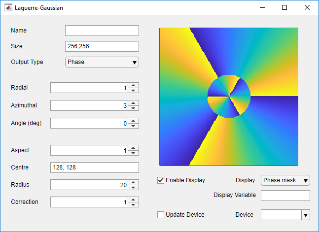
An example of a GUI for the generation of LG beams is shown in
figure 4.
The interface includes a display that can either show the current
phase pattern or the simulated far-field of the SLM. This can be useful
for quickly exploring the capabilities of a particular function.
The user interfaces are contained in the ui sub-package.
A launcher interface has been written to provide an overview and
means to quickly launch the different components.
The user interface provides most of the same functionality as the
command line, patterns are created and added to the Matlab workspace,
allowing the interface to be used interchangeably with the other scripts.
GUI components can be launched by running them from the Matlab browser
or by calling otslm.ui.Launcher once OTSLM has been added to the path.
3.6 Graphics Processing Unit support
For rapidly generating hologram patterns it is possible to use
specialised hardware, such as Graphics Processing Units (GPUs)
[44, 5].
OTSLM currently supports two methods for utilising the GPU: generating
patterns using Matlab’s gpuArray object and directly calculating/drawing
the pattern using OpenGL.
Most functions will automatically detect if the inputs are gpuArray
objects.
For pattern creation functions (such as otslm.simple.* functions)
the GPU can be explicitly enabled via the useGpuArray
optional input argument.
GPUs can be used to accelerate calculations of patterns, however, these
devices often have far less memory than the main computer.
This can create problems when, for instance, combining many large patterns
using otslm.tools.combine.
Instead, it may be necessary to generate individual patterns
and combine them one-by-one, as is done by otslm.tools.lensesAndPrisms.
This method can be relatively effective, using the lenses and prisms algorithm
on a GPU (tested on GTX 1060 6GB; GPUs with less memory should provide
similar performance) we were able to generate a pattern with
11 spots at 60 frames per second, faster than many of the device
we use in the lab for displaying patterns.
One of the main bottlenecks with rapidly generating simple patterns is transferring the patterns from the computer’s main memory into the graphics memory or SLM device memory. In some circumstances this bottleneck can be unavoidable, such as when the device is connected via USB or to another computer on the network. If the device is connected directly to a graphics card it is possible use the GPU to calculate the pattern and display it directly on the device without first copying back to the main computer memory [5]. To achieve this, OTSLM includes an interface to RedTweezers. RedTweezers is a standalone application which draws and displays patterns using an OpenGL enabled graphics card. Pattern creation functions need to be described using OpenGL shader language and compiled into shaders that are loaded onto the GPU. Information about the pattern, such as spot locations, is then sent to the shader and the pattern is calculated and drawn to the screen/device. OTSLM currently includes shaders for the algorithm described in [5] as well as a shader for directly uploading images and utility functions to help with designing a custom shader class.
3.7 Examples
We have tried to include a range of examples for the features included in the toolbox. For beam generation, we suggest the user starts with the simple_beams and advanced_beams examples. For iterative algorithms, we have provided two examples iterative and iterative_3d demonstrating the 2-D and 3-D algorithms currently included. We have also included more specific examples such as a DMD example, different methods for generating a line trap, particle tracking using a SLM and a demonstration to show the effect of phase blur on SLM output. Examples are provided for calibration, imaging and setting up a screen device (window) to control the SLM.
4 Applications
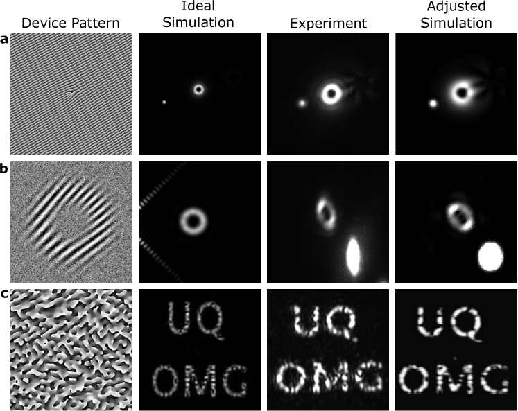
Using the toolbox, we are able to quickly generate and simulate a range of different optical potentials. Figure 5 shows a couple of examples of different device patterns, their simulated far-field, and the experimentally observed far-field on one of our optical systems. By comparing simulations of our beams to the experiment we are able to characterise the imperfections in our optical system. It is then possible to either adjust our simulations to include these imperfections (as shown in the figure), or to modify our experiment to remove these imperfections (either using the SLM or by modifying other components in the system).
One of our main uses for the toolbox is generation of beams in our optical tweezers experiments. We have been using the toolbox for scripted control of optical trap position and generation of optical potentials for orientating biological cells [45]. Being able to programmatically control where optical tweezers are placed allows us to perform repeated measurements of fluid flows by releasing and capturing a probe particle and measuring how far it travels. Using this technique we can map out the velocity flow field generated by a micro-machine or motile micro-organism. Combining OTSLM with the optical tweezers toolbox has also allowed us to simulate the orientation and dynamics of particles in optical traps. We are using this method to design beams to orientate motile micro-organisms in optical traps.
5 Ongoing development
We have made a public repository for our toolbox available on GitHub. We hope that this will enable and encourage collaboration from the community including contributions of algorithms other researchers use. Additionally, we plan to continue to update the toolbox with new features our group develops for optical tweezers problems. Our main interest at the moment is optimising traps for trapping of biological samples in arbitrary orientations. The areas we will focus on are iterative methods and functions to characterise and calibrate the optical systems.
Additionally, there are a couple of tasks we have not had time to work on but we think might be beneficial. We choose to implement the current version in Matlab for the sole reason that our group had pre-existing code in Matlab. It would improve accessibility and in some cases also significantly improve runtime by switching to a non-proprietary language such as Python. Another feature that we would consider if switching to Python is a Pattern class to represent phase/amplitude patterns returned by functions in the toolbox. Keeping track of the pattern phase range (1 or ) can be confusing and sometimes lead to patterns being incorrectly scaled. A separate class for these patterns could keep track of both the pattern data and the other meta-data such as range, date created, functions used to create it.
6 Conclusion
In this paper we have described our new beam shaping toolbox, OTSLM. The toolbox currently includes functions to generate a range of simple diffraction gratings and beam phase/amplitude patterns as well as a selection of common iterative algorithms and tools for working with patterns and devices. Our toolbox includes a graphical user interfaces for some of the most common tasks. The current version of the toolbox is implemented in Matlab and available on GitHub. It is our hope that this toolbox will be useful to the optical trapping community as well as more broadly in other fields where the creation of structured light beams with SLMs is needed. By making the toolbox open source, we hope that it will be extended by other researchers using SLMs for light shaping. We hope that this toolbox will be a useful resources for a wide number of researchers in cognate fields to easily create a needed experimental environment when sculptured light is involved, be it in imaging or biology.
Funding
This research was funded by the Australian Government through the Australian Research Council’s Discovery Projects funding scheme (project DP180101002). Isaac Lenton acknowledges support from the Australian Government RTP Scholarship.
Acknowledgments
We acknowledge the other members of the UQ optical micro-manipulation group, particularly new members of our group who have experienced first hand the lack of easily accessible tools for generating these patterns. We also acknowledge Jannis Kohler and Carter Fairhall who tested early versions of the toolbox.
CRediT authorship contribution statement
Isaac C. D. Lenton: Software, Writing — Original Draft. Alexander B. Stilgoe: Writing — Review & Editing, Supervision. Timo A. Nieminen: Funding Acquisition, Writing — Review & Editing, Supervision. Halina Rubinsztein-Dunlop: Funding Acquisition, Writing — Review & Editing, Supervision.
References
References
- [1] D. G. Grier, Y. Roichman, Holographic optical trapping, Appl. Opt. 45 (5) (2006) 880–887 (Feb 2006). doi:10.1364/AO.45.000880.
- [2] C. Maurer, A. Jesacher, S. Bernet, M. Ritsch-Marte, What spatial light modulators can do for optical microscopy, Laser Photonics Rev. 5 (1) (2011) 81–101 (Jan 2011). doi:10.1002/lpor.200900047.
- [3] A. B. Stilgoe, H. Rubinsztein-Dunlop, T. A. Nieminen, A. V. Kashchuk, Sculptured light and switching for complex systems (Conference Presentation), Complex Light and Optical Forces XII 10549 (2018) 105491C (Mar 2018). doi:10.1117/12.2292771.
- [4] M. Padgett, R. Bowman, Tweezers with a twist, Nat. Photonics 5 (6) (2011) 343 (May 2011). doi:10.1038/nphoton.2011.81.
- [5] R. W. Bowman, G. M. Gibson, A. Linnenberger, D. B. Phillips, J. A. Grieve, D. M. Carberry, S. Serati, M. J. Miles, M. J. Padgett, “Red Tweezers”: Fast, customisable hologram generation for optical tweezers, Comput. Phys. Commun. 185 (1) (2014) 268–273 (Jan 2014). doi:10.1016/j.cpc.2013.08.008.
- [6] E. Pleguezuelos, A. Carnicer, J. Andilla, E. Martín-Badosa, M. Montes-Usategui, HoloTrap: Interactive hologram design for multiple dynamic optical trapping, Comput. Phys. Commun. 176 (11) (2007) 701–709 (Jun 2007). doi:10.1016/j.cpc.2007.03.003.
- [7] SLM Pattern Generator – HOLOEYE Photonics AG, https://holoeye.com/spatial-light-modulators/slm-software/slm-pattern-generator, [Online; accessed 27. Jul. 2018] (Jul 2018).
- [8] Lattice Light Sheet SLM Pattern Generator, https://github.com/tlambert03/llspy-slm (Jul 2018).
- [9] Slm-cg, https://github.com/tiffanyharte/slm-cg, supporting code for Optics Express 25, 11692 (2017). (2017).
- [10] OTSLM Toolbox for Structured Light Methods, https://github.com/ilent2/otslm, will be made accessible with publication of paper. (2019).
-
[11]
M. Woerdemann, C. Alpmann, M. Esseling, C. Denz,
Advanced
optical trapping by complex beam shaping, Laser & Photonics Reviews 7 (6)
(2013) 839–854 (2013).
doi:10.1002/lpor.201200058.
URL https://onlinelibrary.wiley.com/doi/abs/10.1002/lpor.201200058 -
[12]
K. Dholakia, T. Cizmár,
Shaping the future of
manipulation, Nature Photonics 5 (2011) 335 EP –, review Article (May
2011).
URL http://dx.doi.org/10.1038/nphoton.2011.80 - [13] P. H. Jones, O. M. Maragò, G. Volpe, Optical Tweezers by Philip H. Jones, Cambridge Core (Dec 2015). doi:10.1017/CBO9781107279711.
- [14] G. Pesce, G. Volpe, O. M. Maragó, P. H. Jones, S. Gigan, A. Sasso, G. Volpe, Step-by-step guide to the realization of advanced optical tweezers, J. Opt. Soc. Am. B, JOSAB 32 (5) (2015) B84–B98 (May 2015). doi:10.1364/JOSAB.32.000B84.
-
[15]
V. Lerner, D. Shwa, Y. Drori, N. Katz,
Shaping
laguerre-gaussian laser modes with binary gratings using a digital
micromirror device, Opt. Lett. 37 (23) (2012) 4826–4828 (Dec 2012).
doi:10.1364/OL.37.004826.
URL http://ol.osa.org/abstract.cfm?URI=ol-37-23-4826 - [16] A. P. Porfiriev, R. G. Skidanov, Optical manipulation of microobjects using binary diffractive elements, Opt. Mem. Neural Networks 23 (3) (2014) 164–169 (Jul 2014). doi:10.3103/S1060992X14030102.
-
[17]
G. Gauthier, I. Lenton, N. M. Parry, M. Baker, M. J. Davis,
H. Rubinsztein-Dunlop, T. W. Neely,
Direct
imaging of a digital-micromirror device for configurable microscopic optical
potentials, Optica 3 (10) (2016) 1136–1143 (Oct 2016).
doi:10.1364/OPTICA.3.001136.
URL http://www.osapublishing.org/optica/abstract.cfm?URI=optica-3-10-1136 - [18] M. Padgett, R. Di Leonardo, Holographic optical tweezers and their relevance to lab on chip devices, Lab Chip 11 (7) (2011) 1196–1205 (2011). doi:10.1039/C0LC00526F.
- [19] O. Fixler, Z. Zalevsky, Geometrically superresolved lensless imaging using a spatial light, Appl. Opt. 50 (29) (2011) 5662–5673 (Oct 2011). doi:10.1364/AO.50.005662.
- [20] A. Jesacher, C. Maurer, A. Schwaighofer, S. Bernet, M. Ritsch-Marte, Full phase and amplitude control of holographic optical tweezers with high efficiency, Opt. Express 16 (7) (2008) 4479–4486 (Mar 2008). doi:10.1364/OE.16.004479.
- [21] R. W. Gerchberg, O. A Saxton W., A practical algorithm for the determination of phase from image and diffraction plane pictures, Optik 35 (1971) 237–250 (Nov 1971).
- [22] R. Di Leonardo, F. Ianni, G. Ruocco, Computer generation of optimal holograms for optical trap arrays, Opt. Express 15 (4) (2007) 1913–1922 (Feb 2007). doi:10.1364/OE.15.001913.
- [23] R. Di Leonardo, S. Bianchi, Hologram transmission through multi-mode optical fibers, Opt. Express 19 (1) (2011) 247–254 (Jan 2011). doi:10.1364/OE.19.000247.
- [24] J. Peatross, M. Berrondo, D. Smith, M. Ware, Vector fields in a tight laser focus: comparison of models, Opt. Express 25 (13) (2017) 13990–14007 (Jun 2017). doi:10.1364/OE.25.013990.
- [25] P. Vaveliuk, G. F. Zebende, M. A. Moret, B. Ruiz, Propagating free-space nonparaxial beams, J. Opt. Soc. Am. A, JOSAA 24 (10) (2007) 3297–3302 (Oct 2007). doi:10.1364/JOSAA.24.003297.
- [26] N. Delen, B. Hooker, Free-space beam propagation between arbitrarily oriented planes based on full diffraction theory: a fast Fourier transform approach, J. Opt. Soc. Am. A, JOSAA 15 (4) (1998) 857–867 (Apr 1998). doi:10.1364/JOSAA.15.000857.
- [27] G. Shabtay, Three-dimensional beam forming and Ewald’s surfaces, Opt. Commun. 226 (1) (2003) 33–37 (Oct 2003). doi:10.1016/j.optcom.2003.07.056.
- [28] M. Leutenegger, R. Rao, R. A. Leitgeb, T. Lasser, Fast focus field calculations, Opt. Express 14 (23) (2006) 11277–11291 (Nov 2006). doi:10.1364/OE.14.011277.
- [29] Optical Tweezers Toolbox (Version 1), https://github.com/ilent2/ott (2018).
- [30] J. L. de Bougrenet de la Tocnaye, L. Dupont, Complex amplitude modulation by use of liquid-crystal spatial light modulators, Appl. Opt. 36 (8) (1997) 1730–1741 (Mar 1997). doi:10.1364/AO.36.001730.
- [31] L. Zhu, J. Wang, Arbitrary manipulation of spatial amplitude and phase using phase-only spatial light modulators, Sci. Rep. 4 (2014) 7441 (Dec 2014). doi:10.1038/srep07441.
- [32] E. G. van Putten, I. M. Vellekoop, A. P. Mosk, Spatial amplitude and phase modulation using commercial twisted nematic LCDs, Appl. Opt. 47 (12) (2008) 2076–2081 (Apr 2008). doi:10.1364/AO.47.002076.
- [33] S. A. Goorden, J. Bertolotti, A. P. Mosk, Superpixel-based spatial amplitude and phase modulation using a digital micromirror device, Opt. Express 22 (15) (2014) 17999–18009 (Jul 2014). doi:10.1364/OE.22.017999.
- [34] K. J. Mitchell, S. Turtaev, M. J. Padgett, T. Čižmár, D. B. Phillips, High-speed spatial control of the intensity, phase and polarisation of vector beams using a digital micro-mirror device, Opt. Express 24 (25) (2016) 29269–29282 (Dec 2016). doi:10.1364/OE.24.029269.
- [35] T. W. Clark, R. F. Offer, S. Franke-Arnold, A. S. Arnold, N. Radwell, Comparison of beam generation techniques using a phase only spatial light modulator, Opt. Express 24 (6) (2016) 6249–6264 (Mar 2016). doi:10.1364/OE.24.006249.
- [36] J. Courtial, G. Whyte, Z. Bouchal, J. Wagner, Iterative algorithms for holographic shaping of non-diffracting and self-imaging light beams, Opt. Express 14 (6) (2006) 2108–2116 (Mar 2006). doi:10.1364/OE.14.002108.
- [37] S. P. Poland, N. Krstajić, R. D. Knight, R. K. Henderson, S. M. Ameer-Beg, Development of a doubly weighted Gerchberg–Saxton algorithm for use in multibeam imaging applications, Opt. Lett. 39 (8) (2014) 2431–2434 (Apr 2014). doi:10.1364/OL.39.002431.
-
[38]
D. Stuart, O. Barter, A. Kuhn, Fast
algorithms for generating binary holograms, arXiv (Sep 2014).
arXiv:1409.1841.
URL https://arxiv.org/abs/1409.1841 - [39] H. Chen, Y. Guo, Z. Chen, J. Hao, J. Xu, H.-T. Wang, J. Ding, Holographic optical tweezers obtained by using the three-dimensional Gerchberg–Saxton algorithm, J. Opt. 15 (3) (2013) 035401 (Jan 2013). doi:10.1088/2040-8978/15/3/035401.
- [40] G. Whyte, J. Courtial, Experimental demonstration of holographic three-dimensional light shaping using a Gerchberg–Saxton, New J. Phys. 7 (1) (2005) 117 (May 2005). doi:10.1088/1367-2630/7/1/117.
- [41] N. Yoshikawa, T. Yatagai, Phase optimization of a kinoform by simulated annealing, Appl. Opt. 33 (5) (1994) 863–868 (Feb 1994). doi:10.1364/AO.33.000863.
- [42] G. C. Spalding, J. Courtial, R. Di Leonardo, Holographic optical tweezers, Academic Press, 2008 (2008).
- [43] D. Bowman, T. L. Harte, V. Chardonnet, C. De Groot, S. J. Denny, G. L. Goc, M. Anderson, P. Ireland, D. Cassettari, G. D. Bruce, High-fidelity phase and amplitude control of phase-only computer generated holograms using conjugate gradient minimisation, Opt. Express 25 (10) (2017) 11692–11700 (May 2017). doi:10.1364/OE.25.011692.
-
[44]
MartinPersson, HOTlab,
[Online; accessed 18. Nov. 2019] (Sep 2018).
URL https://github.com/MartinPersson/HOTlab - [45] I. C. D. Lenton, D. J. Armstrong, A. B. Stilgoe, T. A. Nieminen, H. Rubinsztein-Dunlop, Orientation of swimming cells with annular beam optical tweezers, Opt. Commun. (2019) 124864 (Nov 2019). doi:10.1016/j.optcom.2019.124864.
Pre-print of:
I. Lenton, et al., OTSLM toolbox for Structured Light Methods, Computer Physics Communications, 2020, 107199, https://doi.org/10.1016/j.cpc.2020.107199.
© 2019. This manuscript version is made available under the CC-BY-NC-ND 4.0
license http://creativecommons.org/licenses/by-nc-nd/4.0/.